Tibial Guides, Tools and Techniques for Resecting the Tibial Plateau
Chao; Nam T.
U.S. patent application number 16/671571 was filed with the patent office on 2020-02-27 for tibial guides, tools and techniques for resecting the tibial plateau. The applicant listed for this patent is ConforMIS, Inc.. Invention is credited to Nam T. Chao.
| Application Number | 20200060692 16/671571 |
| Document ID | / |
| Family ID | 49513134 |
| Filed Date | 2020-02-27 |


View All Diagrams
| United States Patent Application | 20200060692 |
| Kind Code | A1 |
| Chao; Nam T. | February 27, 2020 |
Tibial Guides, Tools and Techniques for Resecting the Tibial Plateau
Abstract
Various patient-specific tibial guide housings, patient-specific tibial guide boxes, and methods of resecting the tibial plateau are disclosed herein.
| Inventors: | Chao; Nam T.; (Marlborough, MA) | ||||||||||
| Applicant: |
|
||||||||||
|---|---|---|---|---|---|---|---|---|---|---|---|
| Family ID: | 49513134 | ||||||||||
| Appl. No.: | 16/671571 | ||||||||||
| Filed: | November 1, 2019 |
Related U.S. Patent Documents
| Application Number | Filing Date | Patent Number | ||
|---|---|---|---|---|
| 15330828 | Nov 7, 2016 | |||
| 16671571 | ||||
| 13865958 | Apr 18, 2013 | 9486226 | ||
| 15330828 | ||||
| 61635270 | Apr 18, 2012 | |||
| Current U.S. Class: | 1/1 |
| Current CPC Class: | A61B 17/157 20130101 |
| International Class: | A61B 17/15 20060101 A61B017/15 |
Claims
1. A system for preparing a tibial plateau of a tibia of a patient, the system comprising: a tibial guide housing, the tibial guide housing comprising: a top side generally opposite a bottom side a front side generally opposite a back side, and a medial side generally opposite a lateral side; a first reference arm having a patient-specific contact surface configured to conform to a first tibial surface, the first tibial surface being a first portion of a superior surface of the tibia; a second reference arm having a patient-specific contact surface configured to conform to a second tibial surface, the second tibial surface being a second portion of the superior surface of the tibia, wherein the back side includes a patient-specific contact surface configured to conform to a third tibial surface, the third tibial surface being a portion of an anterior surface of the tibia, wherein the patient-specific contact surface of the back side has a medial-most edge and a lateral-most edge; a void in at least a portion of the top side, the void sized and positioned such that when the tibial guide housing is positioned on the tibia and the patient-specific contact surfaces of each of the first reference arm, the second reference arm, and the back side are in conforming engagement with the first, second, and third tibial surfaces, respectively, a surgeon is able to view a portion of a peripheral edge of the anterior surface of the tibia, the portion of the peripheral edge of the anterior surface of the tibia having a medial-lateral position disposed between the medial-most edge and the lateral-most edge of the patient-specific surface of the back side; and one or more tibial cutting guide boxes, each of the one or more tibial cutting guide boxes comprising: a guide aperture configured to accommodate a surgical cutting tool and guide the cutting tool along a cutting plane having a predetermined cut depth and angle; and at least one pin hole configured to accommodate a pin passing into the tibia, wherein at least one of the one or more tibial cutting guide boxes is configured for releasable securement within the tibial guide housing.
2. The system of claim 1, wherein the void comprises a viewing window configured to permit viewing of the portion of the peripheral edge of the anterior surface of the tibia from the top side of the tibial guide housing during positioning of the tibial guide housing on the tibia.
3. The system of claim 1, including at least two tibial cutting guide boxes, wherein each of the at least two tibial cutting guide boxes has a different predetermined cut depth.
4. The system of claim 3, wherein each of the at least two tibial cutting guide boxes are configured for releasable securement within the tibial guide housing.
5. The system of claim 1, wherein the patient-specific contact surface of each reference arm is configured to engage an articular surface of the tibial.
6. The system of claim 1, wherein the patient-specific contact surface of each reference arm is configured to engage subchondral bone surface.
7. The system of claim 1, wherein the top side includes a patient-specific alignment indicator configured to provide visual assistance for alignment of the tibial guide housing with respect to the tibia.
8. The system of claim 7, wherein the alignment indicator comprises one or more channels formed in the top surface of the tibial guide housing.
9. The system of claim 7, wherein the alignment indicator is positioned and shaped based, at least in part, on patient-specific information to substantially match a portion of a perimeter of the tibia when the tibial guide housing is positioned on the tibia in a predetermined alignment.
10. The system of claim 1, further comprising an alignment leg, the alignment leg configured for attachment to a tibial alignment rod.
11. The system of claim 1, wherein the tibial guide housing further comprises a third reference arm having a patient-specific contact surface configured to conform to a forth tibial surface.
12. A method of preparing a tibial plateau of a tibia of a knee joint of a patient for implantation of at least one prosthesis, the method comprising: providing a tibial guide housing, the tibial guide housing including: a top side generally opposite a bottom side a front side generally opposite a back side, and a medial side generally opposite a lateral side; a first reference arm having a patient-specific contact surface configured to conform to a first tibial surface, the first tibial surface being a first portion of a superior surface of the tibia; a second reference arm having a patient-specific contact surface configured to conform to a second tibial surface, the second tibial surface being a second portion of the superior surface of the tibia, wherein the back side includes a patient-specific contact surface configured to conform to a third tibial surface, the third tibial surface being a portion of an anterior surface of the tibia, wherein the patient-specific contact surface of the back side has a medial-most edge and a lateral-most edge; a void in at least a portion of the top side, the void sized and positioned such that when the tibial guide housing is positioned on the tibia and the patient-specific contact surfaces of each of the first reference arm, the second reference arm, and the back side are in conforming engagement with the first, second, and third tibial surfaces, respectively, a surgeon is able to view a portion of a peripheral edge of the anterior surface of the tibia, the portion of the peripheral edge of the anterior surface of the tibia having a medial-lateral position disposed between the medial-most edge and the lateral-most edge of the patient-specific surface of the back side; providing a first tibial cutting guide box, the first tibial cutting guide box including: a guide aperture configured to accommodate a surgical cutting tool and guide the cutting tool along a cutting plane having a predetermined cut depth and angle; and at least one pin hole configured to accommodate a pin passing into the tibia; releasably securing the first tibial cutting guide box within an opening of the tibial guide housing; positioning the tibial guide housing on the tibia such that each of the patient-specific contact surfaces of the tibial guide housing achieves a conforming fit with the tibia; and inserting a cutting device through the guide aperture and cutting a portion of the tibia along the cutting plane.
13. The method of claim 12, further comprising removing the first tibial cutting guide box from the tibial guide housing.
14. The method of claim 12, further comprising selecting the first tibial cutting guide box from a plurality of tibial cutting guide boxes, each including a guide aperture having a different predetermined cut depth.
15. The method of claim 12, further comprising: positioning a trial prosthesis component on a cut surface of the tibia; and checking a state of the knee joint, wherein the state of the knee joint is selected from the group consisting of ligament stability of the knee joint, range of motion of the knee joint, alignment of the knee joint, and combinations thereof.
16. The method of claim 15, further comprising: selecting a second tibial cutting guide box from a plurality of tibial cutting guide boxes, each including a guide aperture having a different predetermined cut depth, based, at least in part, on the checking a state of the knee joint; and releasably securing the second tibial cutting guide box within the opening of the tibial guide housing.
Description
RELATED APPLICATIONS
[0001] This application is a continuation of U.S. application Ser. No. 15/330,828, entitled "Tibial Guides, Tools, and Techniques for Resecting the Tibial Plateau" and filed Nov. 7, 2016, which in turn is a continuation of U.S. application Ser. No. 13/865,958, entitled "Tibial Guides, Tools, and Techniques for Resecting the Tibial Plateau" and filed Apr. 18, 2013, which in turn claims the benefit of U.S. Provisional Application Ser. No. 61/635,270, entitled "Tibial Guides, Tools, and Techniques for Resecting the Tibial Plateau" and filed Apr. 18, 2012, the disclosure of each which is incorporated herein by reference in its entirety.
TECHNICAL FIELD
[0002] This disclosure relates to improved and/or patient-adapted (e.g., patient-specific and/or patient-engineered) surgical guides, tools and techniques to assist with the resection of the tibial plateau or similar bones. More specifically, the present disclosure provides a set of alignment and cutting guides and methods for use that are easier and more reliable for use by experienced and inexperienced knee surgeons.
BACKGROUND
[0003] When a patient's knee is severely damaged, such as by osteoarthritis, rheumatoid arthritis, or post-traumatic arthritis, it may be desirous to repair and/or replace portions or the entirety of the knee with a total or partial knee replacement implant. Knee replacement surgery is a well-tolerated and highly successful procedure that can help relieve pain and restore function in injured and/or severely diseased knee joints.
[0004] In a typical knee surgery, the surgeon will begin by making an incision through the various skin, fascia, and muscle layers to expose the knee joint and laterally dislocate the patella. The anterior cruciate ligament may be excised and/or the surgeon may choose to leave the posterior cruciate ligament intact--such soft tissue removal often depends on the surgeon's preference and condition(s) of the ACL/PCL. Various surgical techniques are used to remove the arthritic joint surfaces, and the tibia and femur are prepared and/or resected to accept the component artificial implants.
[0005] Preparing the surface of the tibia often requires that the surgeon resect the articular surface of the bone to receive an implant over the resected surface. The resection can include specific depths of cut(s), posterior slope(s), varus/valgus angle(s), and/or axial alignment(s) that can be unique to every patient. The specific dimensions and/or measurements desirably ensure proper positioning of the artificial joint component assembly, and accurate guiding and cutting of the tibial plateau is important to achieve the most accurate and best fit of the artificial implant components.
[0006] Traditionally, a surgeon has two options to help them prepare the tibia. The surgeon may select the traditional "freehand" method, or he/she may choose a set of surgical instruments that will assist with positioning, resection and alignment. The "freehand" method usually involves standard surgical tools available in the operating room (OR) during surgery, such as osteotomy drills and calipers for measuring. The procedure, preparation, alignment and/or resection may be more or less accurate, depending on the level of the skill and/or ability of the surgeon. Where surgical guide tools are chosen, the surgeon may employ a standard sized saw guide block or other resection guides, which desirably assist with the critical cuts required in the tibial plateau. A saw guide block or resection guide can first be attached to the patient in various ways, and then an alignment device can be used to provide a desired alignment. Once the resection guide is aligned, it can be temporarily fixed in place on the anterior side of the tibia, and the alignment device removed to allow the cutting or resection operation. While the use of such standard sized guide blocks or resection guides can improve the surgical procedure, they may not provide sufficient fine adjustments for cutting depth and/or slope, may be bulky, and may not be easy to use. The misuse or non-use of such devices can result in improper depth of cut, improper posterior slope, malalignment of varus/valgus angle(s), and poor axial alignment that may contribute to poor artificial implant positioning, instability of the joint, and poor surgical outcomes.
[0007] As a result, it has been recognized that it would be desirable to provide a more effective system of guides, tools, instruments and methods to facilitate a high degree of success in the preparation of the tibial plateau to receive an artificial joint.
SUMMARY
[0008] Some disclosed embodiments include a tibial guide housing for use in treatment of a tibia. The tibial guide housing can include a first reference arm with a patient-specific contact surface configured to conform to a first portion of the superior surface of the tibia. The tibial guide housing can also include a second reference arm having a patient-specific contact surface configured to conform to a second portion of the superior surface of the tibia. Additionally, the tibial guide housing can include at least one pin hole configured to accommodate insertion of a pin through the tibial guide housing and into the tibia. The tibial guide housing can also include a patient-specific contact surface configured to conform to a portion of an anterior surface of the tibia.
[0009] Some embodiments can include a system for preparing a tibial plateau. The system can include a tibial guide housing and one or more tibial cutting guide boxes, each of the one or more tibial cutting guide boxes. The tibial cutting guide boxes can include a patient-specific contact surface configured to conform to a portion of the anterior surface of the tibia. The tibial cutting guide boxes can also include a guide aperture configured to accommodate a surgical cutting tool and guide the cutting tool along a cutting plane having a predetermined cut depth and angle. Additionally, the tibial cutting guide boxes can include at least one pin hole configured to accommodate a pin passing into the tibia.
[0010] These and other objects, advantages, and features of the disclosure will be apparent from the following description, considered along with the accompanying drawings.
BRIEF DESCRIPTION OF THE SEVERAL VIEWS OF THE DRAWING
[0011] FIG. 1 depicts a top plan view of one embodiment of a tibial guide housing and/or body;
[0012] FIG. 2 depicts a bottom plan view of the tibial guide housing of FIG. 1;
[0013] FIG. 3 depicts a front view of the tibial guide housing of FIG. 1;
[0014] FIG. 4 depicts a back view of the tibial guide housing of FIG. 1;
[0015] FIG. 5 depicts a right-side view of the tibial guide housing of FIG. 1;
[0016] FIG. 6 depicts a left-side view of the tibial guide housing of FIG. 1;
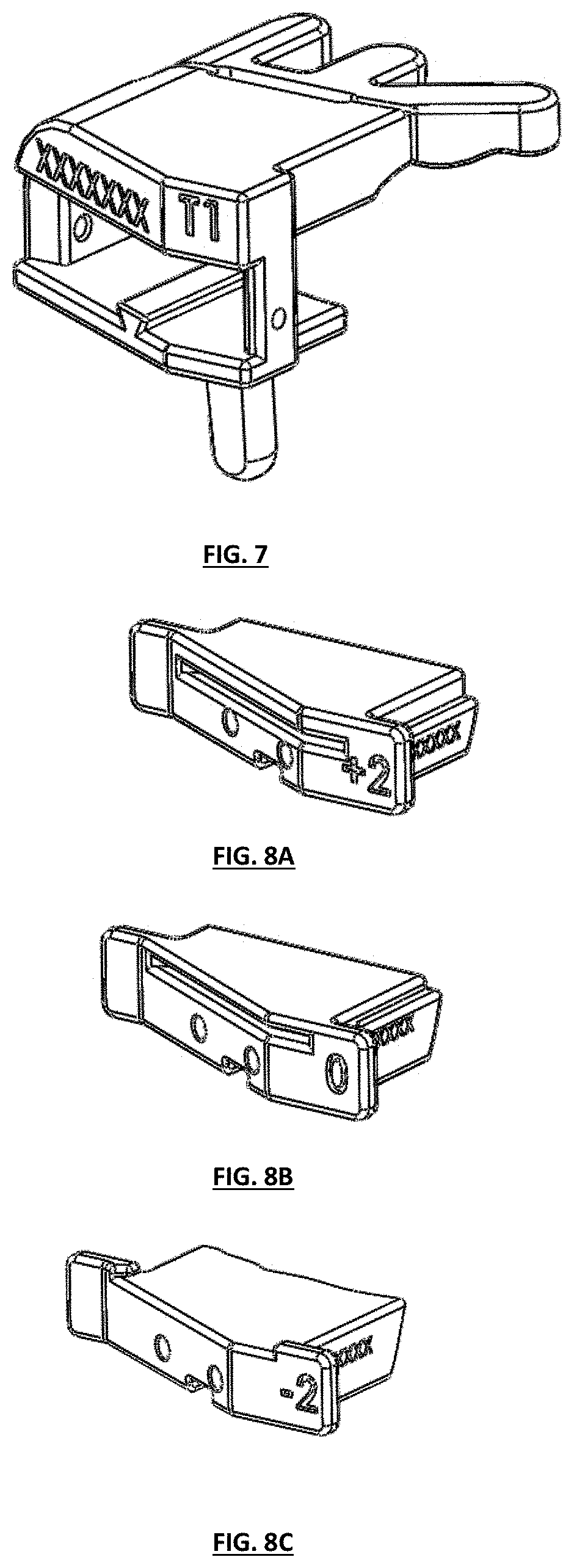
[0017] FIG. 7 depicts an isometric perspective view of the tibial guide housing of FIG. 1;
[0018] FIGS. 8A-8C depict isometric perspective views of different embodiments of tibial guide boxes having various cut depths constructed in accordance with the teaching of the present invention;
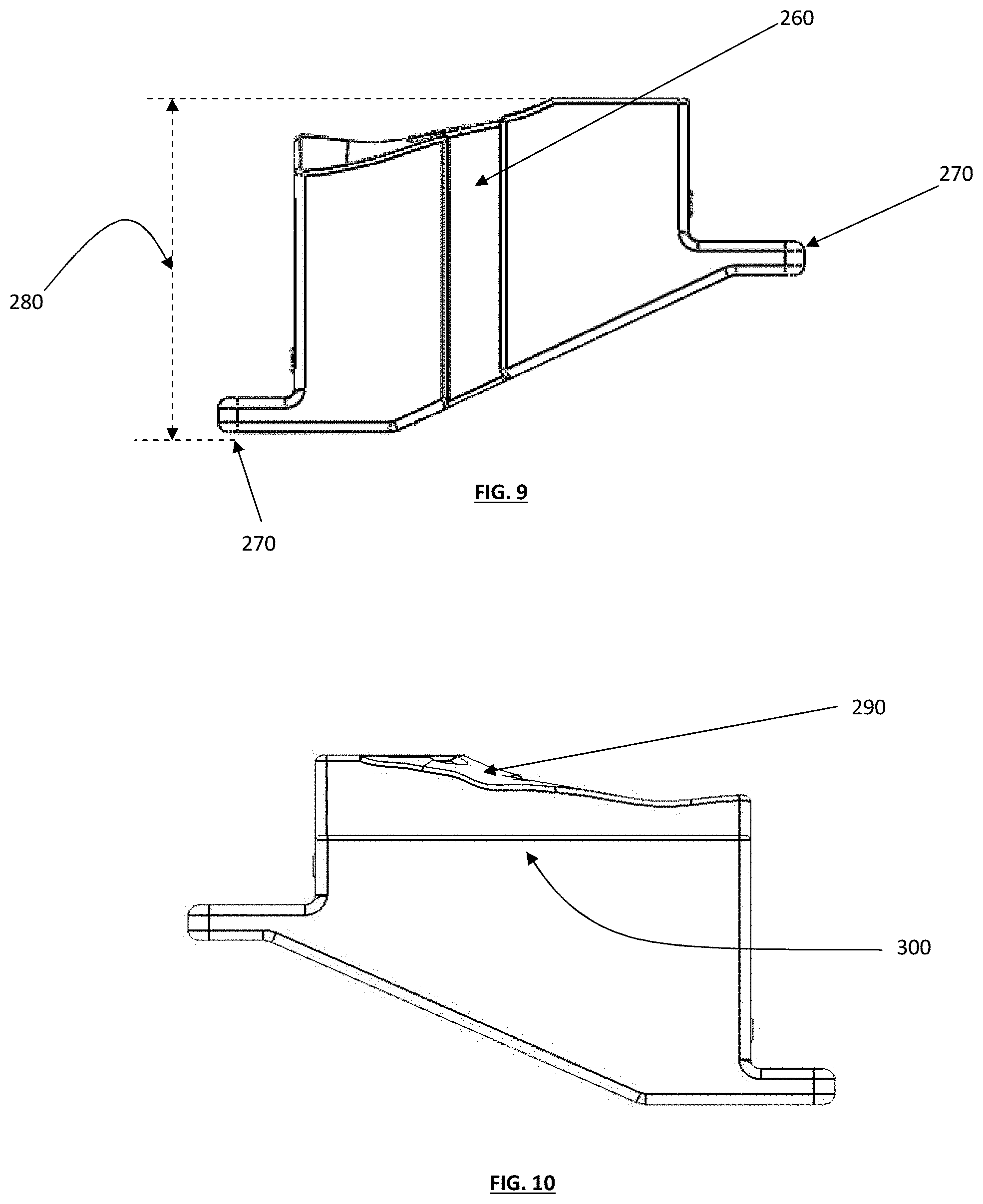
[0019] FIG. 9 depicts a bottom plan view of a tibial guide box;
[0020] FIG. 10 depicts a top plan view of a tibial guide box;
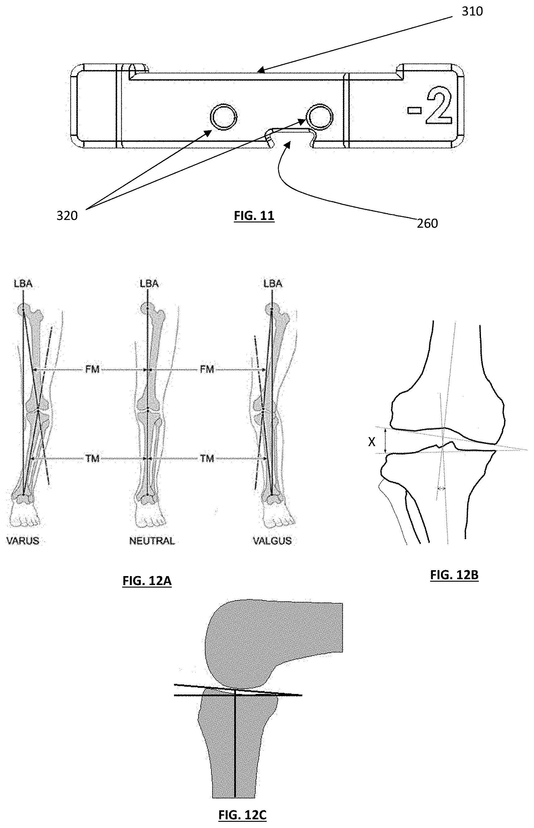
[0021] FIG. 11 depicts a front view of a "minus two cut depth" tibial guide box;
[0022] FIGS. 12A-12C depicts various views of a knee joint at neutral, varus and valgus angles, depicting possible posterior slopes of the knee;
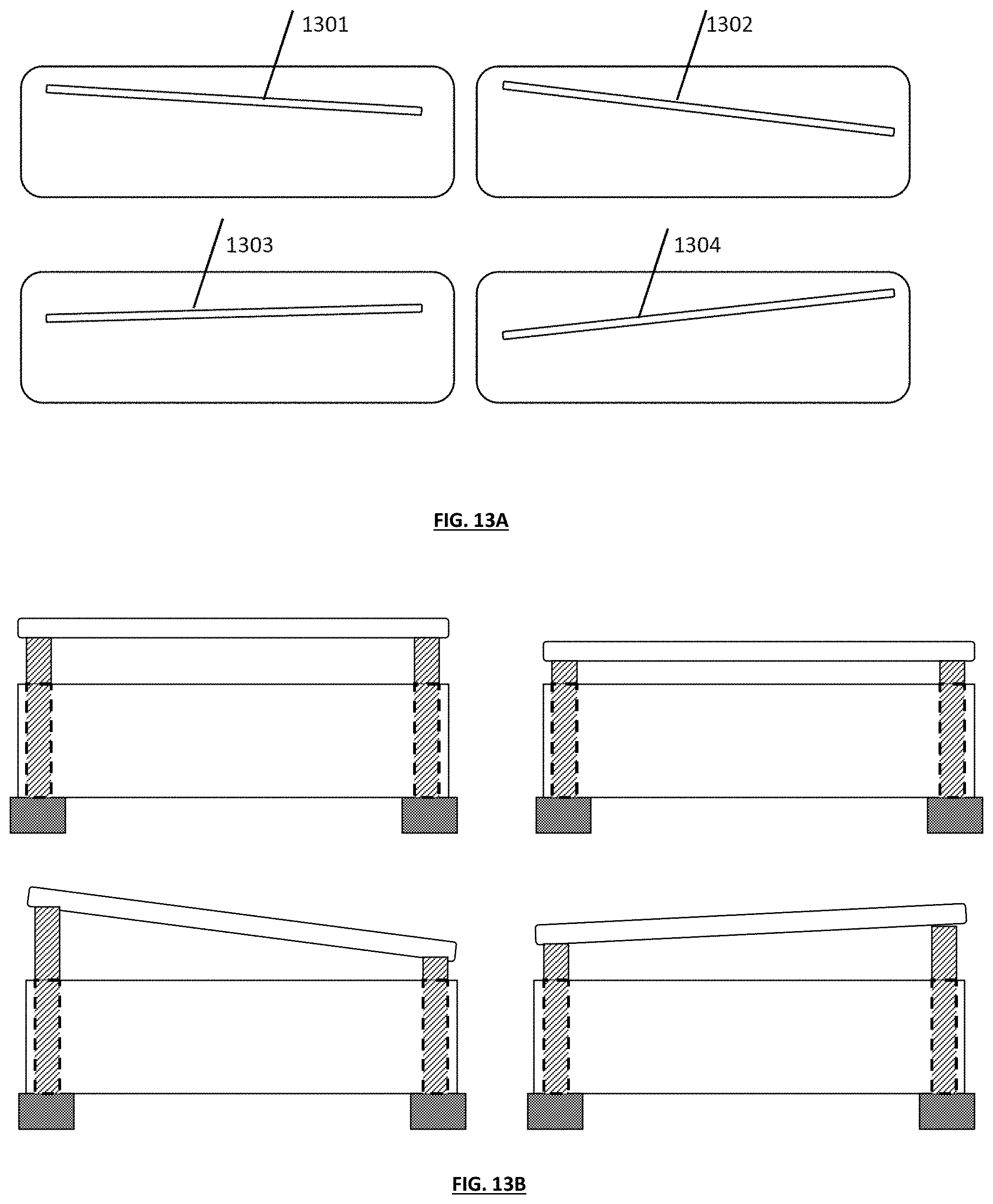
[0023] FIGS. 13A and 13B generally depict various examples varus and valgus guide cut slots that can be designed as standard and/or adjustable features, for adjusting varus/valgus angles;
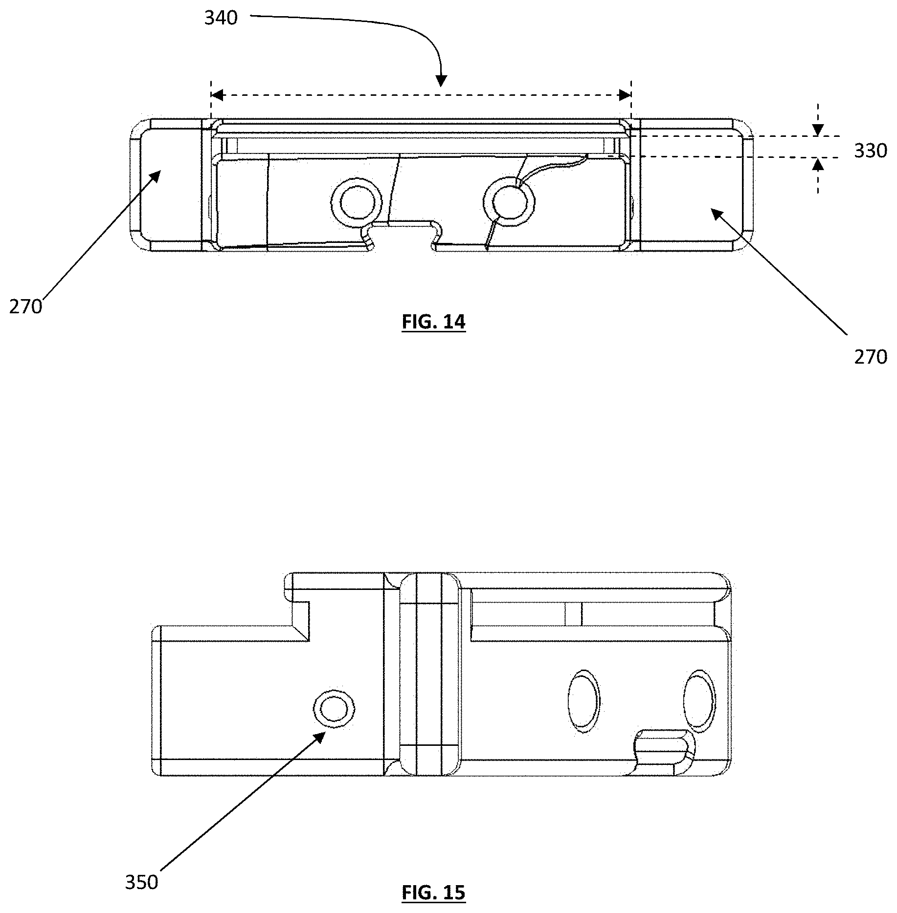
[0024] FIG. 14 depicts a back view of a "zero cut depth" guide box;
[0025] FIG. 15 depicts a side view of the guide box of FIG. 14;
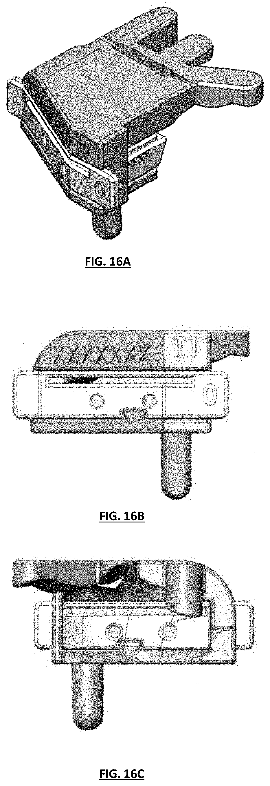
[0026] FIGS. 16A-16C depict isometric perspective, front plan, and back views of one embodiment of an assembled tibial guide assembly;
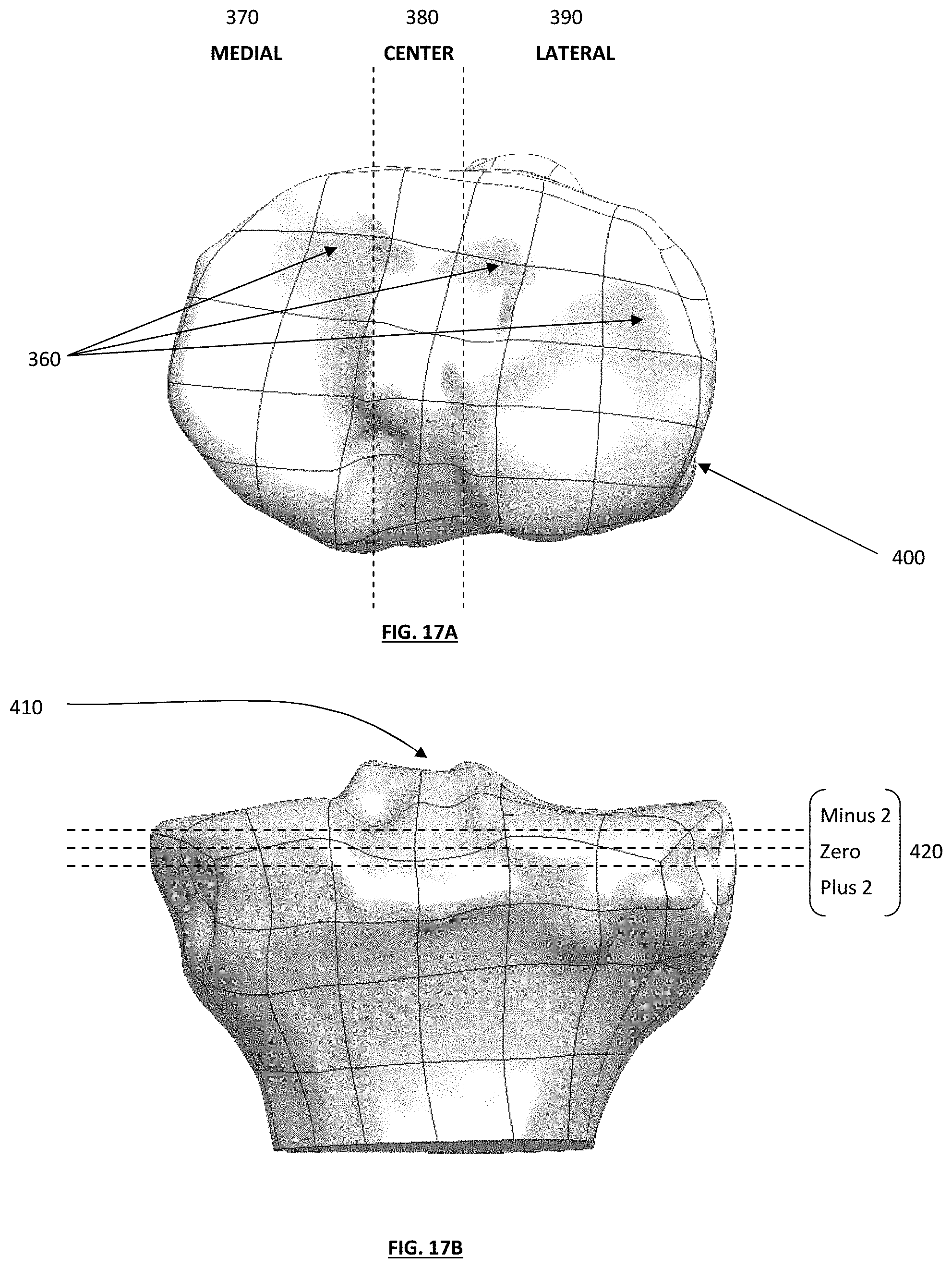
[0027] FIGS. 17A & 17B depict a top plan view and an anterior view of a patient's tibia remodeled by a computer system;
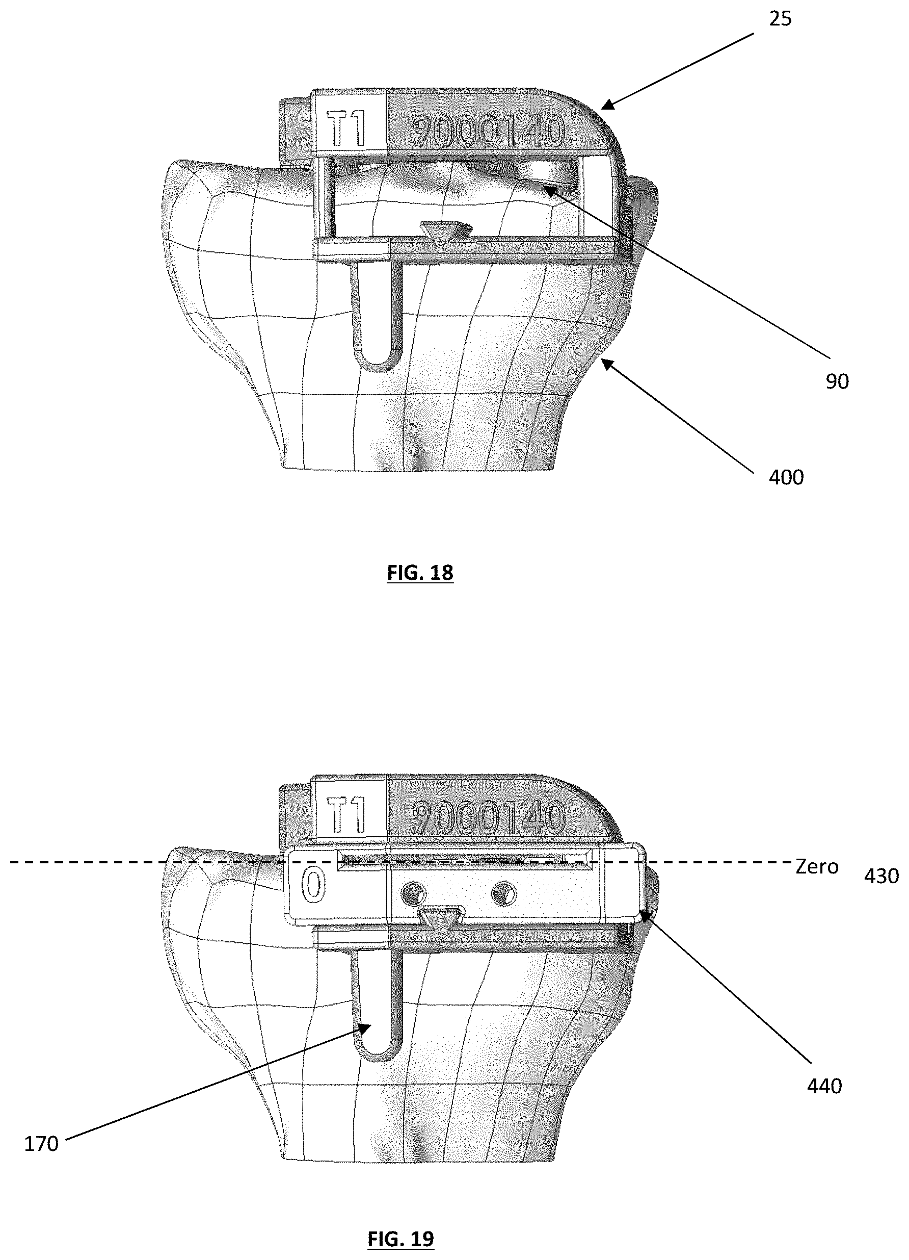
[0028] FIG. 18 depicts an anterior view of a tibial guide housing positioned on a medial side of a tibia;
[0029] FIG. 19 depicts an anterior view of the tibial guide assembly and tibia of FIG. 18, with a "zero" tibial guide box inserted into the tibial guide housing;
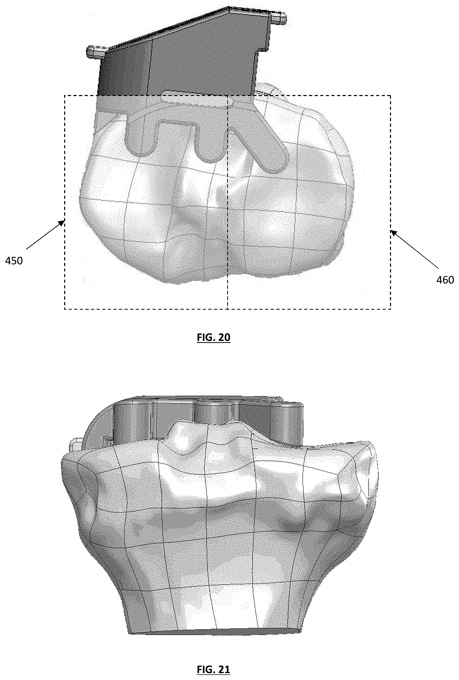
[0030] FIG. 20 depicts a top plan view of a tibial guide assembly, with exemplary medial and lateral cut planes;
[0031] FIG. 21 depicts a posterior view of a tibial guide assembly positioned on a medial side of a tibia;
[0032] FIG. 22 depicts a side view of a tibial guide assembly, with both medial and lateral sides of a tibia resected;
[0033] FIG. 23 depicts a posterior view of the tibial guide assembly with an optional cut plane;
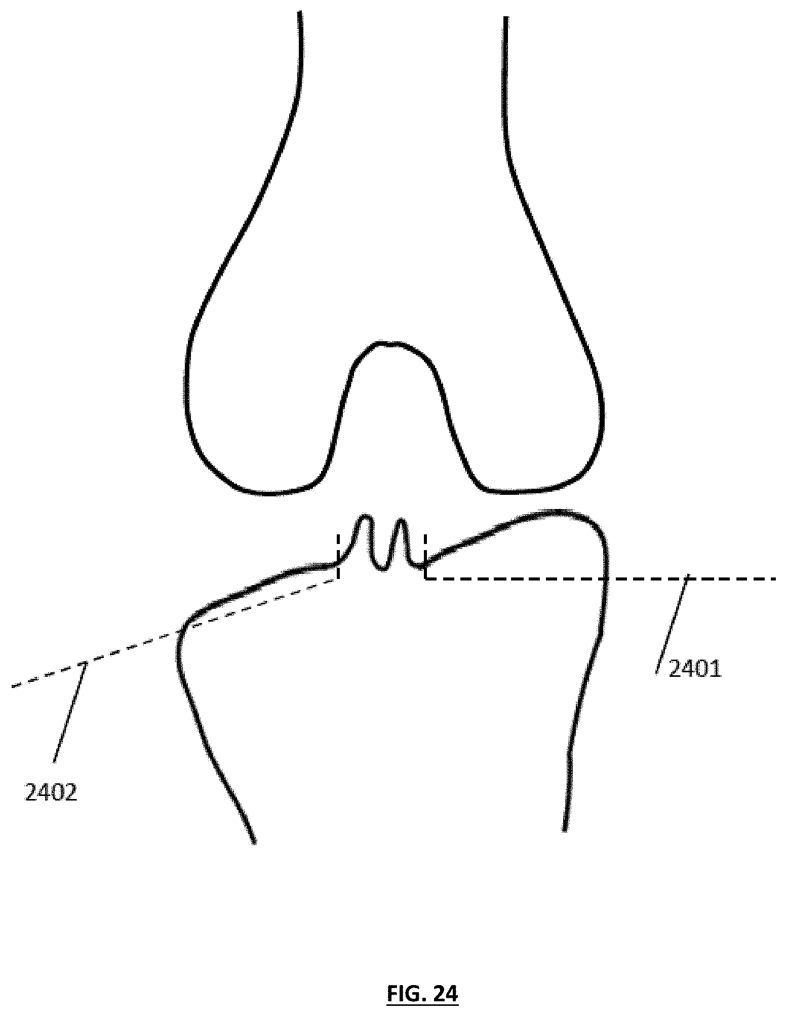
[0034] FIG. 24 depicts an exemplary knee joint with tibial cuts planned to differing levels and depths;
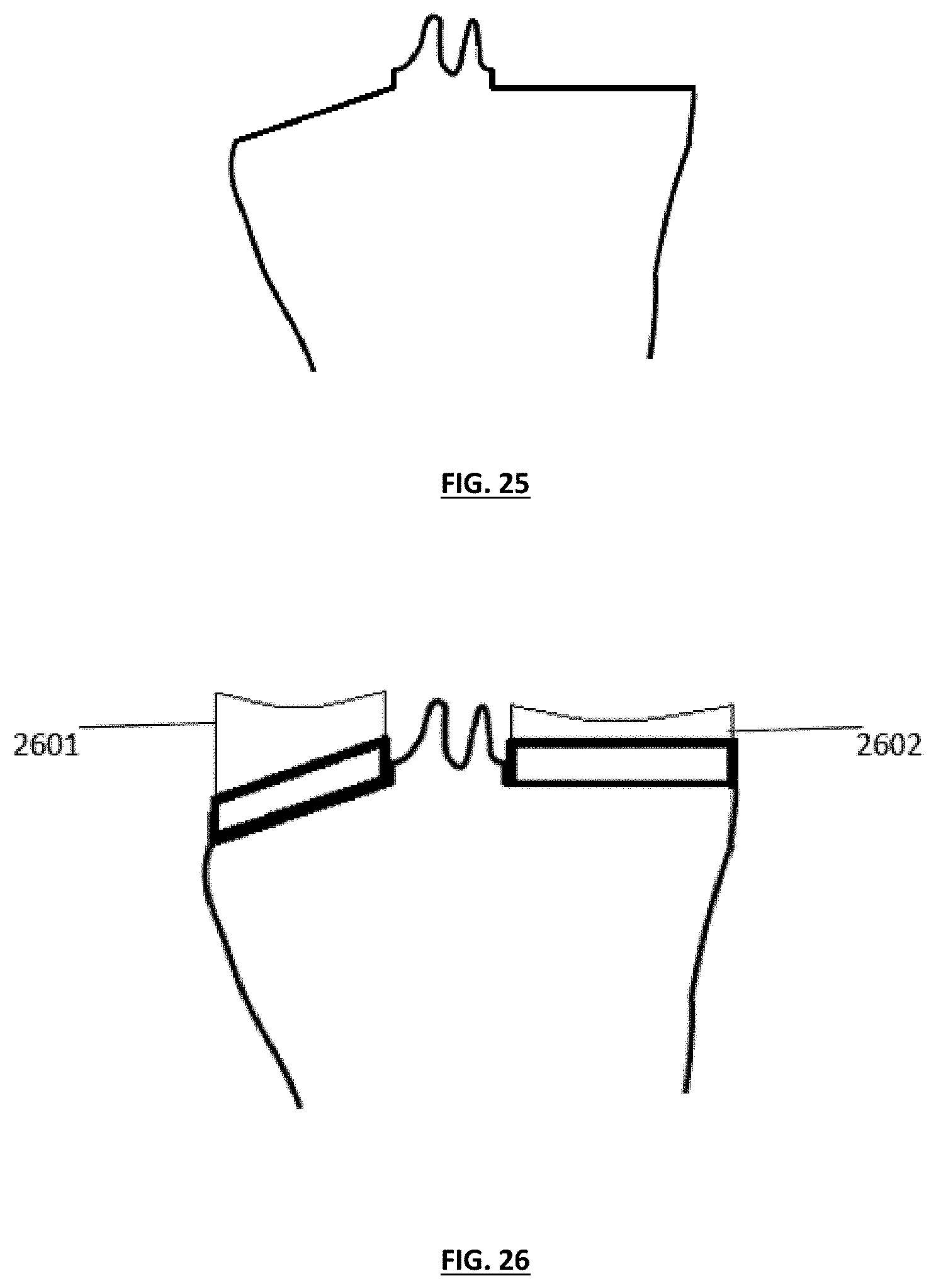
[0035] FIG. 25 depicts the knee joint of FIG. 24 in which a medial tibial section has been resected using a substantially horizontal cut and a lateral tibial section has been resected at a relatively steep angle;
[0036] FIG. 26 depicts the tibia of FIG. 25, wherein a substantially thicker lateral insert than medial insert has been employed to create a desired resulting angulation;
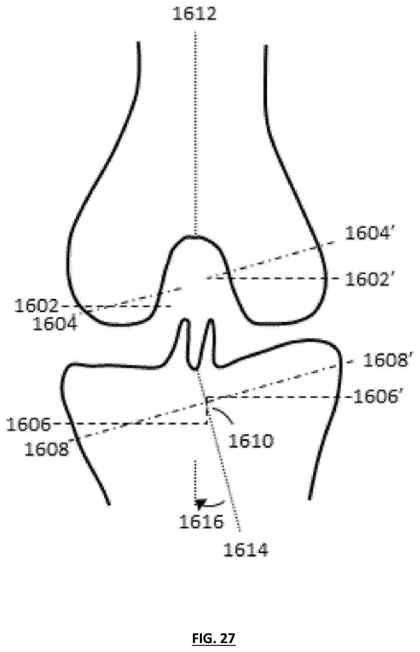
[0037] FIG. 27 illustrates a coronal plane of the knee with exemplary resection cuts that can be used to correct lower limb alignment in a knee replacement;
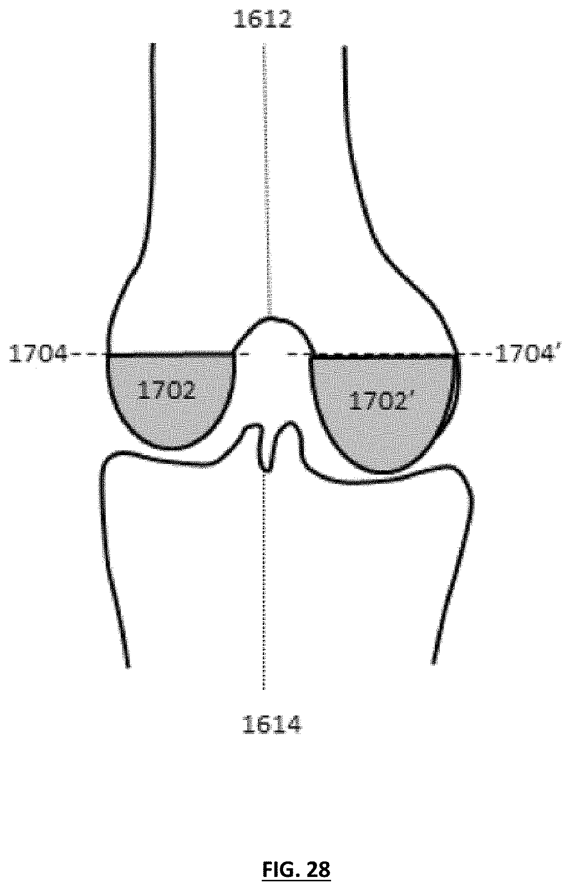
[0038] FIG. 28 depicts a coronal plane of a knee shown with femoral implant medial and lateral condyles having different thicknesses to help to correct limb alignment; and
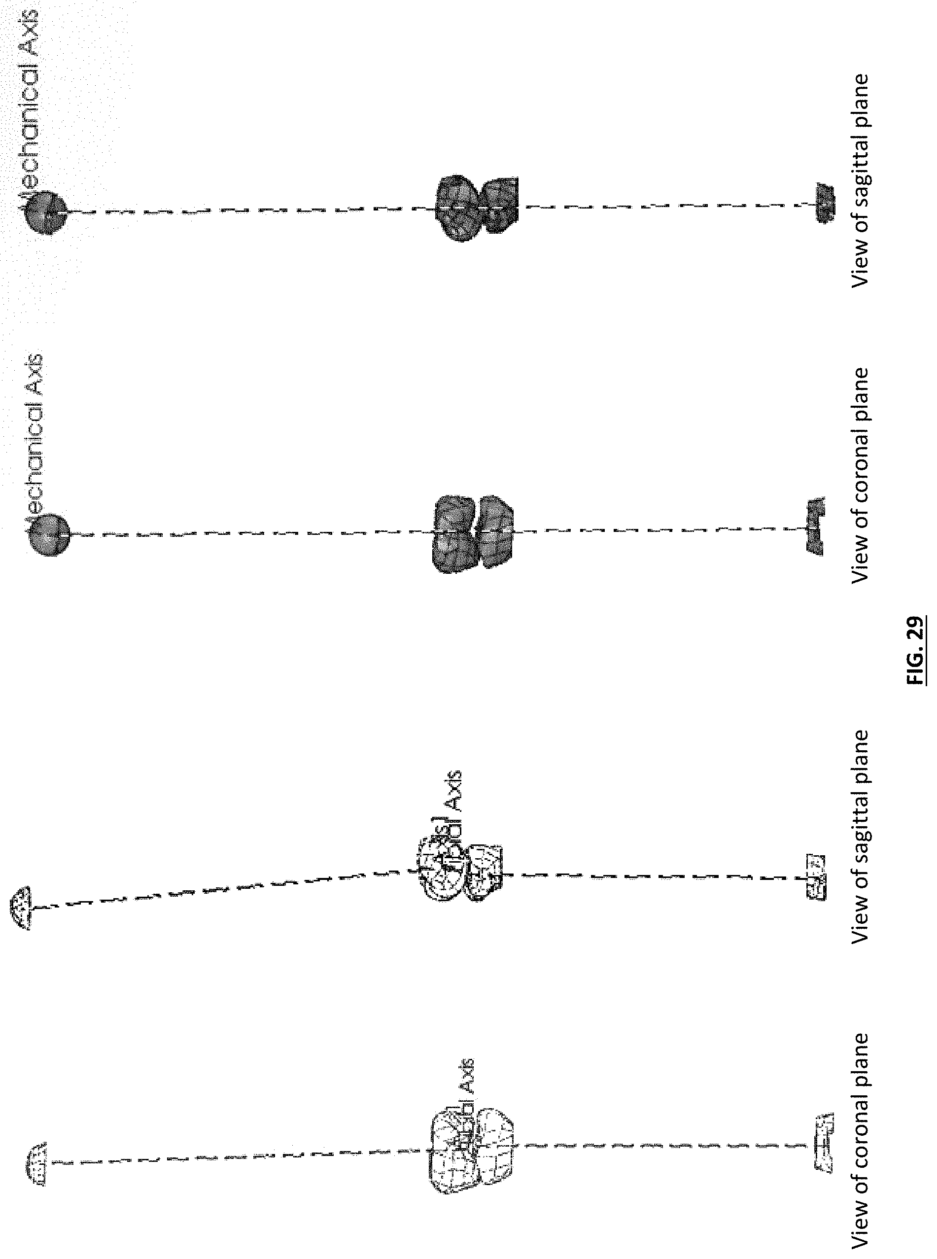
[0039] FIG. 29 illustrates a virtual model of a patient's limb that is misaligned in the sagittal plane, and a virtually corrected limb.
DETAILED DESCRIPTION
[0040] The present disclosure provides an improved patient-specific or patient-engineered tibial resection guide alignment apparatus (hereinafter "resection guide") and associated methods that desirably overcome and/or address various disadvantages of existing systems, as well as provide for controlled depth and/or slope cuts on the tibia. Various embodiments of the present disclosure may be used to facilitate total knee surgery, bicompartmental knee surgery or unicompartmental knee surgery. In addition, the various embodiments can be used for cruciate retaining surgeries or non-cruciate retaining surgeries.
[0041] Various embodiments of the present disclosure may be patient-specific or patient engineered for each surgical patient, with each tibial resection guide alignment apparatus tailored to an individual patient's joint morphology. In at least one preferred embodiment, the system may be designed as an assembly that comprises a patient specific tibial resection housing and/or body and several patient specific sized cutting blocks that can be inserted into the housing/body and used for resecting the tibial plateau.
[0042] In various embodiments, each piece of the tibial resection guide assembly can be uniquely tailored to an individual patient's anatomy, which may require images taken from the subject. The manufacturer can then design the patient-specific resection guide using the joint image from a patient or subject, wherein the image may include both normal cartilage and diseased cartilage; reconstructing dimensions of the diseased cartilage surface to correspond to normal cartilage (using, for example, a computer system) and/or bones; and designing the tibial resection guide to exactly or substantially match the dimensions of the diseased cartilage surface, the normal cartilage surface, a healthy cartilage surface, a subchondral bone surface, and/or various combinations thereof (including height, width, length, and/or reference points of the resection guide). In various alternative embodiments, the guide may substantially match an area slightly greater than the diseased cartilage surface or bone surface (or any other known size that may be applied to any patient).
[0043] The image can be, for example, an intraoperative image including a surface and/or feature detection method using any techniques known in the art, e.g., mechanical, optical, ultrasound, and known devices such as MM, CT, ultrasound, and other image techniques known in the art. In certain embodiments, reconstruction is performed by obtaining a surface that follows the contour of the normal cartilage or the natural anatomy of the bone. The surface can be parametric and include control points that extend the contour of the normal cartilage to the diseased cartilage and/or a B-spline surface to determine the shape of at least one contact surface of the tibial resection guide to fill the areas of diseased cartilage. The images can be 2D or 3D or combination thereof to specifically design the tibial resection guide assembly.
[0044] In various embodiments, tibial resection guide assemblies constructed in accordance with various teachings described herein may be designed as extramedullary or intramedullary. Exemplary extramedullary guides or tools can be connected outside the patient's tibia, and may be designed to include an attachment for alignment rods or any other alignment mechanisms. Exemplary intramedullary alignment guides or tools can include an intramedullary rod that positioned into the central canal of the tibia with the alignment mechanism suspended from the rod.
[0045] Various embodiments can include a patient specific housing and/or body designed to include various reference points that correspond to a patient specific articular contact surface and/or subchondral bone surface (or other surface, as desired). These reference points may be perpendicular extensions or "fingers" that extend from the body to provide tibial surface anchoring. These reference points may include at least one extension, finger or arm that incorporates at least one patient specific contact surface on the articular or other surface of the tibia. The reference points may be designed to have varied lengths onto the surface of the tibia, or may be shortened to the minimum anchoring required. The reference points may be designed centrally located or can be offset to varying degrees to provide an optimal natural conforming location on the articular or other surface of the tibia to allow for stable resection.
[0046] The tibial resection guide assembly can further include one or more guide boxes that may be removably attached to the surface. The boxes may be designed to include various patient specific contact surfaces to easily mate with the anterior surface of the bone. The boxes may have at least one guide aperture for guiding a surgical cutting instrument for controlled resection of the tibia plateau. The guide boxes may also be designed to make cuts that are parallel, non-parallel, perpendicular, or non-perpendicular to other cuts.
[0047] The tibial guide boxes can be designed as removable or permanent. If the tibial guide boxes are removable, they may have a sliding mechanism that allows for easy insertion into the tibial guide resection housing and/or body. They may include other connection arrangements, including rail systems, quick connects, or other similar mechanisms for insertion into and/or connection to the guide resection housing and/or body.
[0048] Various aspects of the disclosed embodiments may be used and/or applied to a variety of other joints, such as the shoulder, hip, and wrist.
Tibial Guide Assembly Apparatus
[0049] Described herein are various embodiments of surgical tools and methods for accurately preparing the medial and lateral tibial plateau such that the plane of each cut across the bone ends will be appropriate to receive the portions of a knee prosthesis selected to reflect the spacing distance and size of the respective bone ends, so that one or more artificial knee joint components will properly and optimally replace the mechanical functioning of a normal knee.
[0050] In various embodiments, the tibial plateau preparation assembly can include: a tibial guide housing, one or more tibial cutting guide boxes with a cutting platform with a tibial depth resection guide, and optional attachment of an alignment rod. In practice, a surgeon, after opening and/or accessing the damaged knee area, may use the tibial guide assembly to prepare medial and lateral ends of a patient's tibia to receive appropriate knee components, such as a tibial tray and insert.
[0051] FIG. 1 depicts a top view of a tibial guide housing and/or body 25. The tibial housing is equipped with a variety of features that will assist the surgeon in his preparation of the tibial plateau; it is designed with a viewing window 20, an alignment indicator 10, an angled low profile body 30 and 40 and ergonomic features 50 and 60. First, the tibial guide housing contains a viewing window 20 to assist the surgeon in placement on the anterior surface of the tibia. This window will allow the surgeon to view the peripheral edge of the anterior surface of the tibia. The window, as depicted in FIG. 1, is designed substantially similar to the width of the tibial guide housing because it maximizes viewing capacity, but may be designed to have a smaller width or a larger height to accommodate the surgeon's need. The dimensions of this window may be designed as standard sizes or shapes or may be patient-specific to accommodate the tibial anatomy. The window may be a variety of shapes such as "Z," or curved shaped, or "L" shaped.
[0052] A second feature is the alignment indicator 10. This indicator provides the surgeon with visual assistance that the housing is firmly planted on the anterior surface of the tibia. The present tibial guide housing has the alignment indicator 10 designed as a small channel. However, the manufacturer may choose to design this indicator on the surface of the housing with additional visual indicators such as an arrow. The alignment indicator may be any size, shape or dimension. The alignment indicator may also be designed as patient specific to match or substantially match the perimeter of the tibia.
[0053] The tibial guide housing may be designed to have a low profile for surgery. A design that is low profile has many advantages because there is often minimal space available above and/or adjacent to the tibia during cruciate ligament retaining procedures. The angled front 30 of the tibial guide housing achieves this purpose. Also, the width 40 of the housing is also smaller than other available cutting guides. The width of the housing 40 minimizes the profile of the cutting guide and may be designed as patient specific.
[0054] The tibial guide housing may be designed to have ergonomic features, such as the extension tab 50 and radiused edges 60. The extension tab 50 allows the surgeon to grasp and handle the tibial guide housing by its edge. The edges within the extension tab are radiused 60 to provide for easy finger transition and no sharp edges. The width of this extension may be designed with varying heights or shapes. The manufacturer may design this with a "U" shape or other variety of shapes to accommodate holding of the housing.
[0055] FIG. 2 depicts a bottom view of the tibial guide housing, showing the reference arms 90, and the patient-specific contact surfaces 70 and 120. The tibial guide housing may be designed with specific reference extensions/arms 90 to help the surgeon find the natural, conforming position for more accurate resection. If the surgeon is resecting the medial side of the tibial plateau, the surgeon will place the reference arms 90 on the articular surface of the tibia and move it around until the reference arms finds their own natural, conforming position(s). The reference arms may be designed with at least one reference arm, but in various preferred embodiments can include three reference arms. The reference arms may respectively be titled as the "medial reference arm," which may align with the center of the medial tibial plateau, the "center reference arm," which can align between the tibial spines, and the "left reference arm," which can align with the center of the tibia. Each reference arm can be made patient specific or be made with standard available sizes retrieved from a database. The reference arms spacing 80 may vary with every patient, or a set spacing may be designed or incorporated between each reference arm. In addition, the medial reference arm and the center reference arm may also have patient-specific angles 100 designed into the housing, or angles 100 may be set standard angles derived from a database. The length 110 of each reference arm may also vary between each patient (i.e., be a patient-specific length). In various embodiments, the tibial guide housing surfaces 120 and 70 that contact the anterior portions of the tibia will be patient specific to provide a secure and conforming fit.
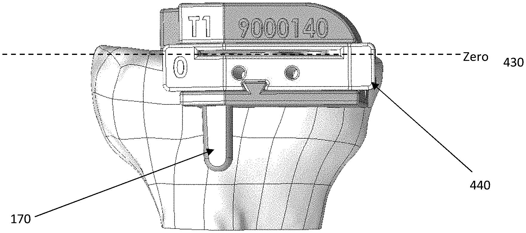
[0056] FIG. 3 depicts a front view of the tibial guide housing. The front view highlights specific features such as the dovetail rail 130, the alignment rod attachment 170, the low profile width 160 and height 150 for tibial guide box insertion, and the tibial guide box positive stops 140. The dovetail rail 130 is designed within the tibial guide housing to allow and/or facilitate easy insertion and securement of the tibial guide boxes (see FIG. 8A-8C). This also allows locking of the tray into the housing and prevents any unnecessary motion or movement during cutting. The tibial guide boxes may be secured into the tibial guide housing using any mechanism that is known in the art. If desired, the tibial guide boxes may be secured by inserting the boxes into the housing and securing by set screws, by press fit, by snap tabs, or other equivalent mechanisms. Alternatively, the bottom may be designed with a recessed tray that seats the tibial guide box.
[0057] The tibial guide housing height 150 and width 160 may be designed specifically to fit one or more of the tibial guide cutting boxes. The dimensions may be minimized to provide a low profile for the assembly, or they may have different shapes to facilitate insertion of the guide boxes. The dimensions may also be patient-specific. The height 150 and/or width 160 may vary depending on the morphology or other features of the damaged or diseased tibia and articular surfaces. The tibial guide housing may also provide positive stop walls 140 to prevent the tibial guide boxes from sliding forward or other directions as well as to potentially prevent the surgeon from over-exerting pressure during insertion. The surgeon can insert the guide box into the guide housing until it reaches a detent or stop to provide accurate alignment. The tibial guide housing may also include an alignment leg 170 to allow attachment of the tibial alignment rod to the body.
[0058] FIG. 4 depicts a back view of the tibial guide housing and highlights the patient contact surfaces 190 and the curved exterior wall 180. The contact surfaces 190 may be patient specific. The image data evaluated to manufacture the housing can be used to design the surface that contacts or mates with the articular surface of the tibial plateau, thus having or approximating a patient specific shape(s). Such features can allow stability and more secure attachment when resecting or cutting is taking place. The exterior wall can be radiused 180, as desired, to eliminate, reduce or minimize soft tissue irritation.
[0059] FIG. 5 depicts a right-side view of the tibial guide housing and/or body. In this view, various detent receiver holes 230 are shown. These detent receiver holes 230 can receive a tibial guide insert box, and in various embodiments the successful insertion can be accompanied by an audible sound or other indication to the surgeon when the box is secured in place. The detent receiver holes 230 can be designed as a receiver for tabs, levers, etc., or they may have different shapes. The alignment leg angle 200 and the alignment leg 220 are also shown in this view. The angle and the length of the alignment leg may be designed as patient specific for increased accuracy in the alignment of the housing to the center axis of the tibia. The alignment leg angle 200 and the height 220 may also be designed as standard dimensions that can be determined from evaluations from a database of various patients. The alignment leg may also be designed to include various connection types, including press fit insertion. For easy removal, the alignment leg may include a quick release/connection mechanism for the surgeon's use that can prevent excessive upward force on the tibial guide housing. This side view also highlights an example of the patient specific nature of the contact surfaces 190 of the tibial guide housing.
[0060] FIG. 6 depicts a left-side view of the tibial guide housing and/or body. This view highlights the relative thickness/height 240 of a reference arm, as well as an exemplary pin hole 250. The reference arm thickness/height 240 may be designed as patient specific. Each reference arm may have different thicknesses/heights to accommodate the diseased patient's surface. The thickness/height of each arm may also be designed to have standard dimensions as derived from a database of similar patients. The tibial guide housing may have one or more pin holes 250 to help secure the housing to the tibia. The pin holes may be designed large enough to accommodate a drill and to insert pins for visual guidance or location on the tibia.
[0061] FIGS. 8A-8C depict isometric perspective views of various embodiments of different tibial guide boxes that can be used with various features disclosed herein, with various available cut depths included in one preferred embodiment. FIG. 8A shows the "+2" tibial guide box that can be employed by the surgeon to make a primary cut to the tibia. This box, along with other system features, desirably facilitates the surgeon's ability to adjust the resection or cut of the tibial plateau after a primary cut has been completed. In the embodiment shown in FIG. 8B, the primary cut can be defined as the "0" tibial guide box. In various procedures, the "0" guide box will be inserted and utilized by the surgeon to make the primary cut and may be, in various embodiments, a patient-specific selected or derived depth. FIG. 8C shows a "-2" guide box which can also allow the surgeon to adjust the cut after the primary cut has been made. Many other cut depths can be created to allow the surgeon to make additional controlled depth cuts on the tibial plateau.
[0062] FIGS. 9 and 10 depict the bottom and top plan views, respectively, of a tibial guide box. In these embodiments, the bottom view of the guide box shows a dovetail rail 260, and the positive stop tabs 270. The dovetail rail 260 may have varying widths or lengths for quick and guided insertion of the tibial guide boxes. The positive stop tabs 270 are designed to extend to contact the positive stop walls 140. FIG. 10 shows that the cut guide cover 300 need not necessarily extend the full depth of the tibial guide box. However, the cut guide cover may be designed to reach the entire length/depth of the tibial guide box. In addition, the cut guide cover may be manufactured out of variety of materials that would withstand an oscillating or reciprocating saw. It can be manufactured out of biocompatible metals and/or plastics.
[0063] FIG. 11 depicts a front view of a minus two cut depth guide box. This specific guide cut box need not necessarily have a cut guide cover 300 because it can use the roof of the tibial guide housing as a portion of the cut guide cover. In contrast, FIGS. 8A and 8B depict guide cut covers 300 that are designed in portions of the boxes. FIG. 11 further depicts two pin holes 320 that may be incorporated into the design of each tibial guide cut box. The tibial guide box may have pin holes 320 to help secure the box to the tibia. The pin holes may be designed large enough to accommodate a drill and to insert pins for visual guidance or location on the tibia. Also, additional pin holes may be designed into the guide box or guide housing. As previously noted, the "-2" guide box still can guide 310 the reciprocating saw or the oscillating saw by using the roof the tibial guide housing as a guide boundary. This guided slot 310 may be manufactured to specific dimensions to accommodate standard oscillating or reciprocating bone saws. In another embodiment, the guided slot 310 may also incorporate various angles, shaped and/or configurations, including different features to accommodate different varus/valgus (see FIG. 13) and/or anterior/posterior angles (see FIG. 12C) designed within the box.
[0064] FIGS. 12A and 12B depict a human knee with exemplary varus, neutral and valgus orientations, and various exemplary angles that a cut guided slot 30 or other tool may incorporate to accommodate and/or correct such orientations. In a varus knee, this line passes medial to the knee and a moment arm is created, which increases force across the medial compartment of the knee. In a valgus knee, the load-bearing axis (LBA) passes lateral to the knee, and the resulting moment arm increases force across the lateral compartment of the knee. In various embodiments, specifically designed tibial guide boxes that incorporate patient specific varus/valgus angles could be employed to reduce and/or correct such deformities, desirably reducing abnormal forces in the artificial knee joint, and returning the LBA to a normal functioning knee at its neutral position. FIG. 13A depicts various cut guide slot angulations that, when used in conjunction with a tibial guide box as described herein, can generally be employed to alter the resulting varus or valgus angles of one or more tibial cut planes. FIG. 13B depicts one alternative embodiment of a guide tool that incorporates an adjustment mechanism 322 that can be employed and adjusted to alter the cut angle. The adjustment mechanism could include a screw thread or other mechanism that allows a wide variation in the cut plane angle, which could include larger wedges to accommodate more severe varus/valgus angles. In various embodiment, the guide tool with the adjustable mechanism could be sized and configured to fit into the standard guided slots 1301-1304 as shown in FIG. 13A.
[0065] In at least one alternative embodiment, various features of guide tools and surgical methods described herein can be used in conjunction with a wide variety of tibial trays, wedges and/or tibial inserts to accommodate the correction and/or reduction of extremely high varus and/or valgus angles in a given patient's anatomy. In such embodiments, a surgeon may choose to resect the medial and lateral portions of the tibia to differing levels and/or depths, as shown in FIG. 24, in which a medial tibial section has been resected using a substantially horizontal cut 2401, and a lateral tibial section has been resected at a relatively steep angle, desirably removing a minimal amount of bone from the lateral side (see FIG. 25). After resection and creation of the respective tibial cut planes, the surgeon can choose to employ various combinations of tibial trays (e.g., separate medial and lateral trays) and/or inserts (e.g., dual inserts) to desirably create and/or replicate medial and lateral tibial condylar surfaces that improve and/or correct the varus and/or valgus angles of one or both of the patient's knee joints. In the embodiment shown in FIG. 26, a substantially thicker lateral insert 2601 (as compared to the thickness of the medial insert 2602) has been employed to create a desired resulting angulation for the knee implant. In one alternative embodiment, a single tibial tray may be used with a single or multiple tibial cuts, with a one or two piece insert having differing thickness on each of the medial/lateral portions in a similar manner.
[0066] In addition, valgus deformities may lead to patients with deformed or hypoplastic lateral condyles. In fact, hypoplastic lateral condyles may be present in 20% of patients that require knee replacement. An implant or tibial guide assemblies or other tools may be engineered from patient-specific data to address this deformity, by correcting or optimizing the lateral condyle, can include one or more expanded curvatures in one or more locations on the lateral condyle, relative to the patient's corresponding uncut medial or lateral condyle. For example, an implant may be engineered to include additional material on the outer, joint-facing surface of the implant component's lateral condyle. The expanded curvature(s) and/or material on the outside of the condyle can be used to design a material savings on the inside of the corresponding section of the implant component, for example, by maintaining a minimum material/implant thickness from the outside (joint-facing surface) to the inside (bone-facing surface) of the implant component. In this way, by adding material to the external contour of the implant component and maintaining a minimum material thickness of the implant component, bone preservation can be maximized. Specifically, with more material on the joint-facing surface of the implant and less material on the inner, bone-facing surface of the implant, the resection cuts are made closer to the surface of the bone. Accordingly, this approach uses the patient-adapted design of the implant component to both correct a condyle shape abnormality, such as a lateral condyle abnormality, such as hypoplasia, and to maximize bone preservation. In another embodiment, the deformity may be corrected by tailoring the tibial resection guide assemblies to have a unique medial and lateral assembly that will correct the angles. For example, the lateral condyle tibial resection guide may require smaller/lesser resection depth cut, different varus/valgus angle, or posterior/anterior angle than the medial tibial resection guide. Other tools and methods may be similarly designed to correct the deformity.
[0067] In an alternative embodiment, the tibial guide assembly, the joint implants, and other tools may be preoperatively designed and/or selected to correct the misalignment and/or obtain a proper mechanical alignment of a patient's limb. For example, based on the difference between the patient's misalignment and the proper mechanical axis, a knee implant and implant procedure can be designed and/or selected preoperatively to include implant and/or resection dimensions that substantially realign the patient's limb to correct or improve a patient's alignment deformity. In addition, the process can include selecting and/or designing one or more surgical tools (e.g., guide tools or cutting jigs) to direct the clinician in resectioning the patient's bone in accordance with the preoperatively designed and/or selected resection dimensions.
[0068] In certain embodiments, the degree of deformity correction that is necessary to establish a desired limb alignment is calculated based on information from the alignment of a virtual model of a patient's limb. The virtual model can be generated from patient-specific data, such 2D and/or 3D imaging data of the patient's limb. The deformity correction can correct varus or valgus alignment or antecurvatum or recurvatum alignment. In a preferred embodiment, the desired deformity correction returns the leg to normal alignment, for example, a zero degree biomechanical axis in the coronal plane and absence of genu antecurvatum and recurvatum in the sagittal plane.
[0069] The preoperatively designed and/or selected implant or implant component, resection dimension(s), and/or cutting guides, templates or cutting jig(s) can be employed to correct a patient's alignment deformity in a single plane, for example, in the coronal plane or in the sagittal plane, in multiple planes, for example, in the coronal and sagittal planes, and/or in three dimensions. For example, where a virtual model of a patient's misaligned lower limb is used to virtually correct the limb, a deformity correction can be achieved by designing and/or selecting one or more of a resection dimension, an implant component thickness, and an implant component surface curvature that adjusts the mechanical axis or axes into alignment in one or more planes. In various embodiments, a lower limb misalignment can be corrected in a knee replacement by designing or selecting one or more of a femoral resection dimension, a femoral implant component thickness, a femoral implant component surface curvature, a tibial resection dimension, a tibial implant component thickness, a tibial implant component insert thickness, and a tibial implant component surface curvature (or various combinations thereof) to adjust the femoral mechanical axis and tibial mechanical axis into alignment in the coronal plane.
[0070] FIG. 27 illustrates a coronal plane of the knee with exemplary resection cuts that can be used to correct lower limb alignment in a knee replacement. As shown in the figure, the selected and/or designed resection cuts can include different cuts on different portions of a patient's biological structure. For example, resection cut facets on medial and lateral femoral condyles can be non-coplanar and parallel 1602, 1602', angled 1604, 1604', or non-coplanar and non-parallel, for example, cuts 1602 and 1604' or cuts 1602' and 1604. Similar, resection cut facets on medial and lateral portions of the tibia can be non-coplanar and parallel 1606, 1606', angled and parallel 1608, 1608', or non-coplanar and non-parallel, for example, cuts 1606 and 1608' or cuts 1606' and 1608. Non-coplanar facets of resection cuts can include a step-cut 1610 to connect the non-coplanar resection facet surfaces. Selected and/or designed resection dimensions can be achieved using one or more selected and/or designed guide tools (e.g., cutting jigs) that guide resectioning (e.g., guide cutting tools) of the patient's biological structure to yield the predetermined resection surface dimensions (e.g., resection surface(s), angles, and/or orientation(s)). In certain embodiments, the bone-facing surfaces of the implant components can be designed to include one or more features (e.g., bone cut surface areas, perimeters, angles, and/or orientations) that substantially match one or more of the resection cut or cut facets that were predetermined to enhance the patient's alignment. As shown in FIG. 27, certain combinations of resection cuts can aid in bringing the femoral mechanical axis 1612 and tibial mechanical axis 1614 into alignment 1616.
[0071] Alternatively, or in addition, certain implant features, such as different implant thicknesses and/or surface curvatures across two different sides of the plane in which the mechanical axes 1612, 1614 are misaligned also can aid correcting limb alignment. For example, FIG. 28 depicts a coronal plane of the knee shown with femoral implant medial and lateral condyles 1702, 1702' having different thicknesses to help to correct limb alignment. These features can be used in combination with any of the resection cut 1704, 1704' described above and/or in combination with different thicknesses on the corresponding portions of the tibial component. As described more fully below, independent tibial implant components and/or independent tibial inserts on medial and lateral sides of the tibial implant component can be used enhance alignment at a patient's knee joint. An implant component can include constant yet different thicknesses in two or more portions of the implant (e.g., a constant medial condyle thickness different from a constant lateral condyle thickness), a gradually increasing thickness across the implant or a portion of the implant, or a combination of constant and gradually increasing thicknesses.
[0072] FIG. 29 illustrates a virtual model of a patient's limb that is misaligned in the sagittal plane, for example, a genu antecurvatum deformity, and the virtually corrected limb. The deformity correction can be achieved using a similar design approach as described above for a coronal plane deformity. However, the selection and/or design of one or more femoral resection dimensions, femoral implant component thicknesses, femoral implant component surface curvatures, tibial resection dimensions, tibial implant component thicknesses, tibial implant component insert thicknesses, and/or tibial implant component surface curvatures can be used to adjust the femoral mechanical axis and tibial mechanical axis into alignment in the sagittal plane (e.g., by altering corresponding features across the sagittal plane, for example, by altering anterior features relative to corresponding posterior features). Alignment deformities in both the coronal and sagittal planes, or in multiple planes about the mechanical axes, can be addressed by designing and/or selecting one or more resection dimensions, one or more implant component thicknesses, and/or one or more implant component surface curvatures.
[0073] In certain embodiments, an implant component that is preoperatively designed and/or selected to correct a patient's alignment also can be designed or selected to include additional patient-specific or patient-engineered features. For example, the bone-facing surface of an implant or implant component can be designed and/or selected to substantially negatively-match the resected bone surface. If resection dimensions are angled, for example, in the coronal plane and/or in the sagittal plane, various features of the implant component, for example, the component bone-facing surface, can be designed and/or selected based on an angled orientation into the joint rather than on a perpendicular orientation. For example, the perimeter of the tibial implant or implant component that substantially positively-matches the perimeter of the patient's cut tibial bone has a different shape depending on the angle of the cut. Similarly, with a femoral implant component, the depth or angle of the distal condyle resection on the medial and/or lateral condyle can be designed and/or selected to correct a patient alignment deformity. However, in so doing, one or more of the implant or implant component condyle width, length, curvature, and angle of impact against the tibia can be altered. Accordingly in certain embodiments, one or more implant or implant component features, such as implant perimeter, condyle length, condyle width, curvature, and angle is designed and/or selected relative to a sloping and/or non-coplanar resection cut.
[0074] FIG. 14 depicts a back view of a tibial guide box. The back view shows a width 340 of the slot and a height 330 of the slot. The width of the guided slot 340 may also be specifically designed to control the width of the cut as required by the surgeon--it may be wider, it may be shorter or a specific cut shape. In various embodiments, the width of the preferred embodiment could substantially match the width of the specific implant components that will be placed on the tibia. The height 330 of the guided slot will desirably determine the cut depth of the tibial plateau, with the angulation of the slot similarly controlling and/or influencing the angulation of the cut plane (in both medial/lateral angulation as well as anterior/posterior angulation). In various embodiments, the cut plane height and/or angulation(s) may be patient specific as determined by each patient's anatomy, or some or all cut plane features could be "dialed in" using an adjustable mechanism as seen in FIG. 13B.
[0075] FIG. 15 depicts a side view of a tibial guide box. The side view highlights the detent 350 which can used in various embodiments to lock into the detent receiver holes 230 (see FIG. 5). One or more of these detents can be placed on opposing sides of the box to ensure that an audible sound is heard (or other indication is provided) when locking the tibial guide box into the tibial guide housing.
[0076] FIGS. 16A-16C depict an isometric view, a front view, and a back view of the tibial guide assembly, respectively. These shaded views show how an exemplary tibial guide box can fit within a corresponding tibial guide housing.
Improved Methods of Using a Tibial Guide Assembly
[0077] One preferred embodiment of the various teachings herein includes providing an apparatus and method for preparing the tibia for a tibial implant that significantly reduces the number of parts and component tools required to resect and prepare a tibial plateau, and desirably reduces the number of steps typically required in such a procedure. One of the many advantages of various embodiments described herein is that the assembly and associated components are modular, which allows the tibial housing to remain attached on the tibia, while multiple tibial guide boxes with varying cut depth dimensions, varus/valgus angles, and posterior/anterior cut angles can be utilized by the surgeon to make additional cuts and/or increase or modify the depth of cuts.
[0078] FIG. 17A depicts a top view of an uncut patient tibia 400 that has been modeled using a computer system. In this embodiment, there are three potential planes that the surgeon will be considering, which are the medial 370, the center 380 and the lateral 390 planes. Each of these planes has varying bone morphology that is shown by the articular ridges 360, and each plane may require a tibial guide assembly that attaches to the bone using the natural conforming bone anatomy adjacent thereto. The natural placement and positioning of an implant using the natural conforming bone anatomy will desirably provide the surgeon with a more secure tool to prepare and cut the tibial plateau.
[0079] FIG. 17B shows an anterior view of a patient's uncut tibia and the medial and lateral intercondylar tubercle 410. This figure highlights the complex anatomy of a tibia and the varying exemplary cut planes 420 that a surgeon may desire in creating one or more desired cut planes to accept a tibial implant. The varying cut planes 420 show that the surgeon has already predetermined the cut depth, the varus/valgus angle, and the posterior/anterior angles that he or she wishes to make to prepare the tibia. However, once the surgeon has made one or more surgical access incisions and is able to directly visualize and/or observe the knee anatomy and the preparation required to cut the knee, the surgeon has the flexibility to adjust the predetermined cuts by using varying modular guide cut boxes with different cut depths and/or angles. For example, in one embodiment, if the surgeon wishes to cut less bone than originally predetermined, then the surgeon may choose the "Minus 2" tibial guide box instead of the "zero" guide box. This will allow the surgeon to cut less bone than what was originally predetermined.
[0080] FIG. 18 depicts an anterior view of a tibial guide housing 25 positioned on the medial side of the tibia 400 and showing the reference arms with a patient specific contact surface 90 conforming to the natural anatomy of the bone; the resection guide is aligned primarily to match natural landmarks of the articular surface or other features of the tibial plateau. Once a desired natural conforming position is found, the surgeon may score the articular surface to reach the subchondral bone to ensure proper positioning and placement, if desired. After the position has been determined, the surgeon may choose to determine the patient's mechanical axis with reference to their anatomical axis with an alignment rod or equivalent systems. For example, an alignment rod may be attached to a tibia guide housing 170 as shown in FIG. 19 and can extend to the patient's ankle to be parallel to the tibia's mechanical axis. The alignment rod system may be designed to be telescoped between its two connection points, which assists with the alignment of the patient's mechanical axis and provides preferred positioning that may be adjustable. The use of the alignment rod may, in various embodiments, provide the surgeon with an additional confirmation that the housing 170 is aligned with the correct patient-specific anatomy.
[0081] Once the alignment system is positioned, the tibial guide housing may be attached to the tibia using known methods and tools available in the OR, or provided in an instrument kit; and such attachment may include securement using a pin arrangement, e.g., by fitting one or more pins through appropriate openings in the tibial guide box (see FIG. 6) and/or the tibial guide housing. In various embodiments, after attaching the tibial guide housing to the anterior surface of the bone, a predetermined or adjusted tibial guide box may be inserted into the tibial guide housing. A reciprocating saw or similar cutting device can be fitted through a cutting guide slot in the tibial guide box and reciprocated or otherwise manipulated or employed to cut across the medial side 450 (see FIG. 20) tibial plateau with a predetermined or adjusted cutting plane 430. If the surgeon is satisfied with the cut, the entire tibial guide assembly may be removed and, if desired, the guide pins may be left in place and the steps may be repeated for the lateral side of the tibia using another lateral side tibial guide assembly. FIG. 20 depicts the top view of the tibial guide assembly and exemplary medial 450 and lateral 460 cut planes.
[0082] FIG. 22 depicts a side view of a tibial guide assembly after both medial 450 and lateral 460 sides of the tibia have been resected; this figure highlights the uniformity of the entire cut tibial surface 460 when using the tibial guide assembly and captured/guided cut boxes. In various alternative embodiments, the medial and lateral cut planes may not be parallel, offset, and/or coplanar. At this time, the surgeon can remove the tibial guide assembly leaving the positioning pins for both the medial and lateral cuts in place to conduct a trialing and fixation of the knee prosthesis. The trialing may involve fitting the prosthesis components to the prepared surfaces and checking the patient's range of motion, alignment, and the ligament stability that will approximate the range of motion of a natural knee. In at least one exemplary embodiment, the proximal tibial end can preferably be first fitted with a variety of templates and measuring tools and be followed by fitting the femur portion of the prosthesis to the prepared distal femur end.
[0083] If various trialing steps do not optimally fit the trial implant prosthesis, additional cuts on the tibia may be made. For example, if the knee is tight in extension and flexion, the tibia may be further resected as necessary using the tibial guide assembly and adjusting the tibial guide boxes 480 (in FIG. 23) to preferred cut depth and angles. If the knee is tight in extension and balanced in flexion, the distal femur may be cut. Lastly, if the knee is tight in flexion and balanced in extension, it is possible that the surgeon may choose a tibial guide cut box to add posterior/anterior slope to the already cut tibial surface. However, many other combinations may be found to optimally adjust the cut depth 470 of the tibia resected surface using the guide boxes and combinations of guide boxes with varying dimensions or angles.
[0084] Once the proper alignment and balancing of the trial implants have been performed, the surgeon may secure the actual knee joint components and patella prosthesis to the patella. The result can be tested and thereafter the incision into the knee can be appropriately closed and dressed.
* * * * *
D00000
D00001
D00002
D00003
D00004
D00005
D00006
D00007
D00008
D00009
D00010
D00011
D00012
D00013

D00014
D00015
D00016
D00017
D00018
XML
uspto.report is an independent third-party trademark research tool that is not affiliated, endorsed, or sponsored by the United States Patent and Trademark Office (USPTO) or any other governmental organization. The information provided by uspto.report is based on publicly available data at the time of writing and is intended for informational purposes only.
While we strive to provide accurate and up-to-date information, we do not guarantee the accuracy, completeness, reliability, or suitability of the information displayed on this site. The use of this site is at your own risk. Any reliance you place on such information is therefore strictly at your own risk.
All official trademark data, including owner information, should be verified by visiting the official USPTO website at www.uspto.gov. This site is not intended to replace professional legal advice and should not be used as a substitute for consulting with a legal professional who is knowledgeable about trademark law.