Robotic Vacuum Cleaner
Thomas; Kevin L. ; et al.
U.S. patent application number 16/610581 was filed with the patent office on 2020-02-27 for robotic vacuum cleaner. The applicant listed for this patent is TTI (Macao Commercial Offshore) Limited. Invention is credited to David Khalil, James Materdo, Kevin L. Thomas, Todd Zimmerman.
| Application Number | 20200060487 16/610581 |
| Document ID | / |
| Family ID | 62223309 |
| Filed Date | 2020-02-27 |


| United States Patent Application | 20200060487 |
| Kind Code | A1 |
| Thomas; Kevin L. ; et al. | February 27, 2020 |
ROBOTIC VACUUM CLEANER
Abstract
A robotic vacuum cleaner is provided having a suction source, a dirt collector, a floor sensor, a primary brush, and an auxiliary brush. The floor sensor includes an emitter and a detector having an intersecting region.
| Inventors: | Thomas; Kevin L.; (Indian Trail, NC) ; Khalil; David; (College Park, MD) ; Materdo; James; (Charlotte, NC) ; Zimmerman; Todd; (Simpsonville, SC) | ||||||||||
| Applicant: |
|
||||||||||
|---|---|---|---|---|---|---|---|---|---|---|---|
| Family ID: | 62223309 | ||||||||||
| Appl. No.: | 16/610581 | ||||||||||
| Filed: | May 7, 2018 | ||||||||||
| PCT Filed: | May 7, 2018 | ||||||||||
| PCT NO: | PCT/US2018/031348 | ||||||||||
| 371 Date: | November 4, 2019 |
Related U.S. Patent Documents
| Application Number | Filing Date | Patent Number | ||
|---|---|---|---|---|
| 62503143 | May 8, 2017 | |||
| Current U.S. Class: | 1/1 |
| Current CPC Class: | A47L 2201/04 20130101; A47L 11/4011 20130101; A47L 9/2826 20130101; A47L 9/0477 20130101; A47L 2201/00 20130101; A47L 2201/06 20130101; A47L 11/4036 20130101; A47L 9/14 20130101; A47L 9/0466 20130101 |
| International Class: | A47L 9/04 20060101 A47L009/04; A47L 9/28 20060101 A47L009/28; A47L 9/14 20060101 A47L009/14; A47L 11/40 20060101 A47L011/40 |
Claims
1. A robotic vacuum cleaner comprising: a suction source; a dirt collector; a floor sensor, the floor sensor including an emitter and a detector, the emitter and detector having an intersecting region; a primary brush; and an auxiliary brush rotatable about a vertical axis positioned a predetermined distance from the floor sensor, the auxiliary brush having a radial extent, wherein the auxiliary brush is configured to not interfere with operation of the floor sensor, and wherein the auxiliary brush is positioned such that the radial extent of the brush does not extend into the intersecting region.
2. A robotic vacuum cleaner according to claim 1, wherein a radius of the auxiliary brush is in a range from 0.8 to 1.6 times the predetermined distance measured from the vertical axis to the floor sensor.
3. A robotic vacuum cleaner according to claim 1, wherein a radius of the auxiliary brush is in a range from 1.0 to 1.5 times the predetermined distance measured from the vertical axis to the floor sensor.
4. A robotic vacuum cleaner according to claim 1, wherein a radius of the auxiliary brush is about 1.2 times the predetermined distance measured from the vertical axis to the floor sensor.
5-11. (canceled)
Description
CROSS-REFERENCE TO RELATED APPLICATIONS
[0001] This application claims priority to U.S. Provisional Patent Application No. 62/503,143, filed May 8, 2017, the entire contents of which are hereby incorporated by reference herein.
BACKGROUND
[0002] The present invention relates to vacuum cleaner and more particular to robotic vacuum cleaners.
BRIEF DESCRIPTION OF THE DRAWINGS
[0003] FIG. 1 is a perspective view of a robotic vacuum cleaner.
[0004] FIG. 2 is a bottom side view of the robotic vacuum cleaner of FIG. 1.
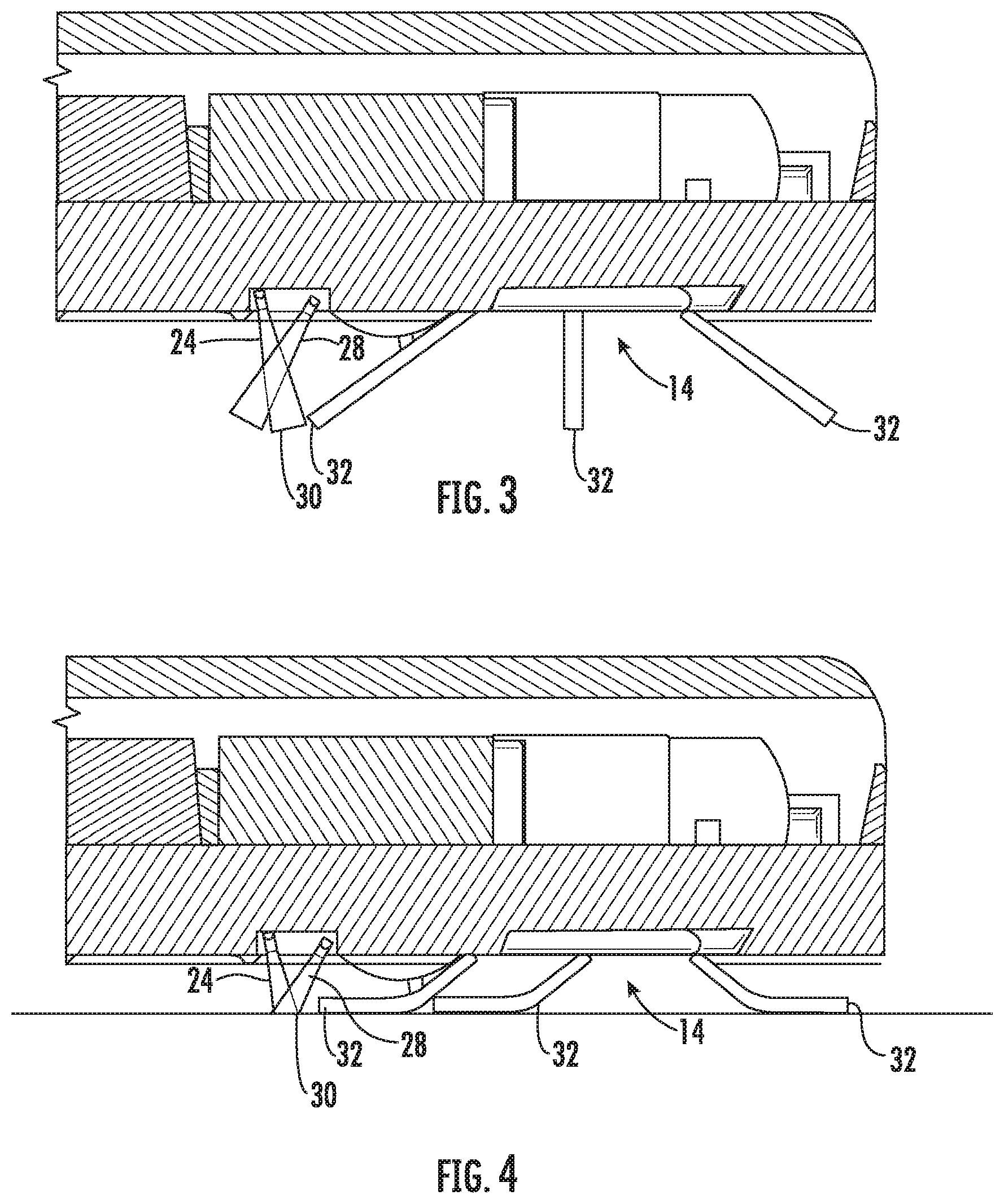
[0005] FIG. 3 illustrates an auxiliary brush and floor sensor of the robotic vacuum cleaner of FIG. 1.
[0006] FIG. 4 illustrates the auxiliary brush for the robotic vacuum cleaner of FIG. 3 with the brush bent in response to contact with the surface being cleaned.
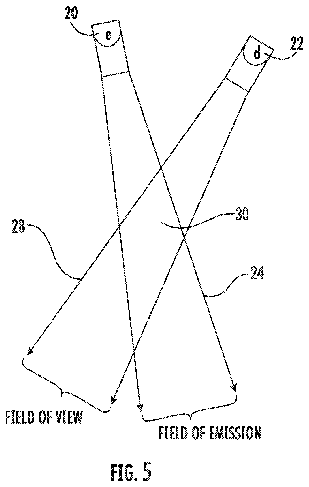
[0007] FIG. 5 is a schematic illustration of a floor sensor for the vacuum of FIG. 1.
[0008] FIG. 6 illustrates an alternative embodiment of an auxiliary brush for the robotic vacuum cleaner of FIG. 1.
[0009] FIG. 7 illustrates an alternative embodiment of an auxiliary brush for the robotic vacuum cleaner of FIG. 1.
[0010] FIG. 8 illustrates an alternative embodiment of an auxiliary brush for the robotic vacuum cleaner of FIG. 1.
[0011] FIG. 9 illustrates an alternative embodiment of an auxiliary brush for the robotic vacuum cleaner of FIG. 1.
[0012] FIG. 10 illustrates an alternative embodiment of an auxiliary brush for the robotic vacuum cleaner of FIG. 1.
[0013] FIG. 11 illustrates an alternative embodiment of an auxiliary brush for the robotic vacuum cleaner of FIG. 1.
[0014] Before any embodiments of the invention are explained in detail, it is to be understood that the invention is not limited in its application to the details of construction and the arrangement of components set forth in the following description or illustrated in the following drawings. The invention is capable of other embodiments and of being practiced or of being carried out in various ways.
DETAILED DESCRIPTION
[0015] FIG. 1 illustrates a robotic vacuum cleaner 10. The vacuum cleaner 10 includes a primary brush 12 and an auxiliary brush 14. The brushes 12 and 14 are rotated about a rotational axis to direct debris toward a suction airstream generated by suction source (e.g., motor and fan) that draws the debris into a dirt collector 16. The primary brush 12 rotates about a generally horizontal rotational axis and the auxiliary brush 14 rotates about a generally vertical axis. Air and debris are separated in the dirt collector 16 and the debris is retained in the collector 16 and the relatively clean airstream is discharged from the vacuum cleaner 10.
[0016] Referring to FIGS. 2 and 5, the robotic vacuum cleaner 10 further includes floor sensors 18. In one embodiment the floors sensors 18 are infrared (IR) sensors each having an infrared emitter 20 and an infrared detector 22. The infrared emitter 20 has a field of emission 24 and the infrared detector 22 has a field of view 28. The field of emission 24 and the field of view 28 intersect at an intersecting region 30. When a floor surface is in the intersecting region 30, infrared light from the IR emitter 20 is sensed on the floor surface by the IR detector 22. When there is no floor surface in the intersecting region 30, the IR detector 22 is used to determine the absence of a floor surface. The lack of IR light from the emitter 20 that is being sensed by the detector 22 in the region 30 is used to make the determination that there is no floor surface below the floor sensor 18. The presence of a floor surface is used to control movement of the robotic vacuum 10. For example, if there is a floor surface present, the robotic vacuum 10 will continue to automatically move along the floor surface. If there is no floor surface present (e.g., the robotic vacuum has reached the edge of a stair), the robotic vacuum will stop or change direction.
[0017] As illustrated in FIGS. 2-4, the auxiliary brush 14 is positioned below the floor sensor 18. However, in the embodiment of FIGS. 1-4, the floor sensor 18 and the auxiliary brush 14 are positioned such that ends of the brush tips 32 do not extend into the intersecting region 30. Therefore, the position of the auxiliary brush 14 and the floor sensor 18 allows the IR emitter 20 and IR detector 22 to properly function to sense whether a floor surface is present because the emission and detection fields 24 and 26 pass by the ends of the brush tips 32 and the brush 14 does not interfere with operation of the sensor 18.
[0018] A position of the intersecting region 30 depends on the orientation of the infrared emitter 20 and detector 22 of the floor sensor 18 relative to one another. In one embodiment, the emitter 20 and the detector 22 are orientated such that the intersecting region 30 is formed at a position distanced away from the center of the auxiliary brush 14. By shifting the formed intersecting region 30 away from the auxiliary brush 14, additional space is provided below the housing of the floor sensor 18 in which to accommodate at least a portion of the auxiliary brush 14 (e.g., brush tips 32) below the housing of the floor sensor 18, such that a portion of the auxiliary brush extends underneath the housing of the floor sensor 18 without extending into the intersecting region 30 interfering with operation of the floor sensor 18. In a specific embodiment, a portion of the auxiliary brush 14 is positioned below the housing of the floor sensor 18 but does not extend into the intersecting region 30.
[0019] The auxiliary brush 14 has a radial extent 17, or radius, and is positioned a predetermined distance 15 from the housing of the floor sensor 18. In one embodiment, the radial extent 17, or radius of the auxiliary brush 14 is between 0.8 and 1.6 times the distance 15 between the center of the auxiliary brush 14 and the housing of the floor sensor 18. In another embodiment, the radius 17 of the auxiliary brush 14 is between 1.0 and 1.25 times the distance 15 between the center of the auxiliary brush 14 and the housing of the floor sensor 18. In yet another embodiment, the radius 17 of the auxiliary brush 14 is approximately 1.2 times the distance 15 between the center of the auxiliary brush 14 and the housing of the floor sensor 18.
[0020] FIGS. 6-11 illustrate possible auxiliary brush embodiments for use with the vacuum 10 where the interference between the auxiliary brush and the floor sensor is minimized or avoided so that the auxiliary brush does not interfere with operation of the floor sensor. In the embodiments of FIGS. 6-11 portions of the brush would pass through the intersecting region 30 of the sensor 18. However, the sensor 18 still properly operates for the reasons discussed below.
[0021] FIG. 6 illustrates an auxiliary brush 34. The brush 34 includes bristles 36 that are substantially evenly spaced 360 degrees around the perimeter of the brush 34. The bristles 36 have different lengths such that the ends of the bristles 36 define an outer perimeter 38 that is generally oval shaped in the illustrated embodiment. The perimeter could have different shapes (e.g., elliptical) in other embodiments. The bristles 36 in region 40 have a relatively long length, which allows these bristles 36 to reach out and capture debris. The bristles 36 in region 42 have a relatively short length, which allows the IR emitter 20 and IR detector 22 to properly function to sense whether a floor surface is present because the emission and detection fields 24 and 26 are able to pass through region 42.
[0022] FIG. 7 illustrates an auxiliary brush 46. The brush 46 includes microfiber fingers 48. The microfiber fingers 48 are spaced 360 degrees around the perimeter of the brush 46. In the illustrated embodiment, the microfiber fingers 48 have generally the same length. The microfiber fingers 48 are spaced such that there is a gap 50 between adjacent fingers 48. The gaps 50 allows the IR emitter 20 and IR detector 22 to properly function to sense whether a floor surface is present because the emission and detection fields 24 and 26 are able to pass through the gaps 50.
[0023] FIG. 8 illustrates an auxiliary brush 54. The brush 54 includes a single bunch of bristles 56 extending from a hub 58. The single bunch of bristles 56 when rotated reaches out and capture debris and directs the debris toward the suction airstream and dirt collector 16. The single bunch or grouping of bristles 56 allows the IR emitter 20 and IR detector 22 to properly function to sense whether a floor surface is present because the emission and detection fields 24 and 26 are able to pass through open areas to the side of the bristle bunch 56.
[0024] FIG. 9 illustrates an auxiliary brush 60. The brush 60 includes bristles 62 that are generally evenly spaced 360 degrees around the perimeter of the brush 60. The bristles 62 are not attached in groups or bunches but rather as individual bristles 62 spaced around the brush 60. The spacing between adjacent bristles 62 allows the IR emitter 20 and IR detector 22 to properly function to sense whether a floor surface is present because the emission and detection fields 24 and 26 are able to pass between the spaced bristles 62.
[0025] FIG. 10 illustrates an auxiliary brush 66. The brush 66 includes a pad 68 having apertures 70. The pad 68 can be formed from microfiber, cloth, or any suitable cleaning pad material. The apertures 70 allow the IR emitter 20 and IR detector 22 to properly function to sense whether a floor surface is present because the emission and detection fields 24 and 26 are able to pass through the apertures 70.
[0026] FIG. 11 illustrates an auxiliary brush 78. The brush 78 includes a pad 80 having fingers 82. The pad 80 can be formed from microfiber, cloth, or any suitable cleaning pad material. The fingers 82 have generally the same length. The fingers 82 are spaced such that there is a gap 84 between adjacent fingers 82. The gaps 84 allows the IR emitter 20 and IR detector 22 to properly function to sense whether a floor surface is present because the emission and detection fields 24 and 26 are able to pass through the gaps 84.
* * * * *
D00000
D00001
D00002
D00003
D00004
D00005
D00006
D00007
XML
uspto.report is an independent third-party trademark research tool that is not affiliated, endorsed, or sponsored by the United States Patent and Trademark Office (USPTO) or any other governmental organization. The information provided by uspto.report is based on publicly available data at the time of writing and is intended for informational purposes only.
While we strive to provide accurate and up-to-date information, we do not guarantee the accuracy, completeness, reliability, or suitability of the information displayed on this site. The use of this site is at your own risk. Any reliance you place on such information is therefore strictly at your own risk.
All official trademark data, including owner information, should be verified by visiting the official USPTO website at www.uspto.gov. This site is not intended to replace professional legal advice and should not be used as a substitute for consulting with a legal professional who is knowledgeable about trademark law.