Primer Diffuser For Polymer Ammunition Cartridges
Burrow; Lonnie
U.S. patent application number 16/596181 was filed with the patent office on 2020-02-20 for primer diffuser for polymer ammunition cartridges. This patent application is currently assigned to TRUE VELOCITY IP HOLDINGS, LLC. The applicant listed for this patent is TRUE VELOCITY IP HOLDINGS, LLC. Invention is credited to Lonnie Burrow.
| Application Number | 20200056872 16/596181 |
| Document ID | / |
| Family ID | 57452384 |
| Filed Date | 2020-02-20 |

| United States Patent Application | 20200056872 |
| Kind Code | A1 |
| Burrow; Lonnie | February 20, 2020 |
PRIMER DIFFUSER FOR POLYMER AMMUNITION CARTRIDGES
Abstract
The present invention provides a diffuser cup or ring adapted to hold a primer used in an ammunition cartridge comprising a bottom surface sized to fit in a primer recess for an ammunition cartridge; a diffuser aperture positioned through the bottom surface and aligned with a flash hole; a cup wall attached to the bottom surface and extending away from the bottom surface; and an interior cavity bordered by the cup wall and the bottom surface and sized to frictionally fit a primer.
| Inventors: | Burrow; Lonnie; (Carrollton, TX) | ||||||||||
| Applicant: |
|
||||||||||
|---|---|---|---|---|---|---|---|---|---|---|---|
| Assignee: | TRUE VELOCITY IP HOLDINGS,
LLC Garland TX |
||||||||||
| Family ID: | 57452384 | ||||||||||
| Appl. No.: | 16/596181 | ||||||||||
| Filed: | October 8, 2019 |
Related U.S. Patent Documents
| Application Number | Filing Date | Patent Number | ||
|---|---|---|---|---|
| 14731731 | Jun 5, 2015 | |||
| 16596181 | ||||
| 14011202 | Aug 27, 2013 | 9546849 | ||
| 14731731 | ||||
| 13292843 | Nov 9, 2011 | 8561543 | ||
| 14011202 | ||||
| 61456664 | Nov 10, 2010 | |||
| Current U.S. Class: | 1/1 |
| Current CPC Class: | F42C 19/0807 20130101; F42C 19/10 20130101 |
| International Class: | F42C 19/08 20060101 F42C019/08; F42C 19/10 20060101 F42C019/10 |
Claims
1. A diffuser cup adapted to hold a primer used in an ammunition cartridge comprising: a bottom surface sized to fit in a primer recess for an ammunition cartridge; a diffuser aperture positioned through the bottom surface and aligned with a flash hole; a cup wall attached to the bottom surface and extending away from the bottom surface; and an interior cavity bordered by the cup wall and the bottom surface and sized to frictionally fit the primer.
2. The diffuser cup of claim 1, wherein the diffuser cup comprises a metal, an alloy, a composite or a polymer.
3. The diffuser cup of claim 1, further comprising an adhesive applied to the bottom surface to contact a primer.
4. The diffuser cup of claim 1, further comprising an adhesive applied to the bottom surface to contact the primer recess.
5. The diffuser cup of claim 1, further comprising a primer positioned in the interior cavity.
6. A diffuser ring adapted to separate a primer and a primer recess in an ammunition cartridge comprising: a diffuser ring sized to fit in a primer recess for an ammunition cartridge having a bottom surface opposite a top surface; and a diffuser aperture positioned through the bottom surface and the top surface to align with a flash hole of the ammunition cartridge.
7. The diffuser ring of claim 6, wherein the diffuser ring comprises a metal, an alloy, a composite or a polymer.
8. The diffuser ring of claim 6, further comprising an adhesive applied to the bottom surface to contact a primer.
9. The diffuser ring of claim 6, further comprising an adhesive applied to the bottom surface to contact the primer recess.
10. The diffuser ring of claim 6, further comprising an adhesive applied to the top surface to contact the primer.
11. The diffuser ring of claim 6, further comprising a primer positioned in the interior cavity.
Description
CROSS-REFERENCE TO RELATED APPLICATIONS
[0001] This application is a Divisional Application of U.S. patent application Ser. No. 14/731,731 filed on Jun. 5, 2015, which is a Continuation-in-Part of U.S. patent application Ser. No. 14/011,202 filed on Aug. 27, 2013 now U.S. Pat. No. 9,546,849 issued Jan. 17, 2017, which is a Divisional Application of U.S. patent application Ser. No. 13/292,843 filed on Nov. 9, 2011 now U.S. Pat. No. 8,561,543 issued Oct. 22, 2013, which claims the benefit of U.S. Provisional Patent Application Ser. No. 61/456,664, filed Nov. 10, 2010, the contents of each are hereby incorporated by reference in their entirety.
TECHNICAL FIELD OF THE INVENTION
[0002] The present invention relates in general to the field of ammunition primers, specifically to compositions of matter and methods of making and using primers having a diffuser for use with polymer ammunition cartridges.
STATEMENT OF FEDERALLY FUNDED RESEARCH
[0003] None.
INCORPORATION-BY-REFERENCE OF MATERIALS FILED ON COMPACT DISC
[0004] None.
BACKGROUND OF THE INVENTION
[0005] Without limiting the scope of the invention, its background is described in connection with primers for polymer cartridge casing ammunition. Conventional ammunition cartridge casings for rifles and machine guns, as well as larger caliber weapons, are made from brass, which is heavy, expensive, and potentially hazardous. There exists a need for an affordable lighter weight replacement for brass ammunition cartridge cases that can increase mission performance and operational capabilities. Lightweight polymer cartridge casing ammunition must meet the reliability and performance standards of existing fielded ammunition and be interchangeable with brass cartridge casing ammunition in existing weaponry. Reliable cartridge casing manufacturing requires uniformity (e.g., bullet seating, bullet-to-casing fit, casing strength, etc.) from one cartridge to the next in order to obtain consistent pressures within the casing during firing prior to bullet and casing separation to create uniformed ballistic performance. Plastic cartridge casings have been known for many years but have failed to provide satisfactory ammunition that could be produced in commercial quantities with sufficient safety, ballistic, handling characteristics, and survive physical and natural conditions to which it will be exposed during the ammunition's intended life cycle; however, these characteristics have not been achieved. Shortcomings of the known plastic or substantially plastic ammunition include the possibility of the projectile being pushed into the cartridge casing, the bullet pull being too light such that the bullet can fall out, the bullet pull being too insufficient to create sufficient chamber pressure, the bullet pull not being uniform from round to round, and portions of the cartridge casing breaking off upon firing or insufficient sealing about the primer. To overcome the above shortcomings, improvements in cartridge casing design and performance polymer materials are needed.
[0006] U.S. Pat. No. 7,610,858 discloses a cylindrical drum design to eliminate the need for the adhering method in the primer's design, while providing protection against the effects of temperature variance, age, and physical movement of the cartridge. It provides continuous operable positioning of the priming mixture between the firing pin and the anvil without requiring the addition of glue to the priming mixture and includes a cylindrical disk with a shelf for containing an amount of starter priming mixture that replaces the conical anvil.
BRIEF SUMMARY OF THE INVENTION
[0007] The present invention provides a diffuser cup adapted to hold a primer used in an ammunition cartridge comprising a bottom surface sized to fit in a primer recess for an ammunition cartridge; a diffuser aperture positioned through the bottom surface and aligned with a flash hole; a cup wall attached to the bottom surface and extending away from the bottom surface; and an interior cavity bordered by the cup wall and the bottom surface and sized to frictionally fit a primer. The diffuser cup may be in part or entirely comprise a metal, an alloy, a composite or a polymer. The diffuser cup may further include an adhesive applied to the bottom surface to contact a primer, an adhesive applied to the bottom surface to contact the primer recess or both. The diffuser cup may further include a primer positioned in the interior cavity.
[0008] The present invention provides a diffuser ring adapted to separate a primer and a primer recess in an ammunition cartridge comprising a diffuser ring sized to fit in a primer recess for an ammunition cartridge having a bottom surface opposite a top surface; and a diffuser aperture positioned through the bottom surface and the top surface to align with a flash hole of the ammunition cartridge.
[0009] The diffuser ring may be made in part or entirely from a metal, an alloy, a composite or a polymer. The diffuser ring may further include an adhesive applied to the bottom surface to contact a primer, an adhesive applied to the bottom surface to contact the primer recess, an adhesive applied to the top surface to contact the primer or a combination thereof. The diffuser ring may further include a primer positioned in the interior cavity.
BRIEF DESCRIPTION OF THE SEVERAL VIEWS OF THE DRAWINGS
[0010] For a more complete understanding of the features and advantages of the present invention, reference is now made to the detailed description of the invention along with the accompanying figures and in which:
[0011] FIG. 1 depicts an exploded view of the polymeric cartridge casing;
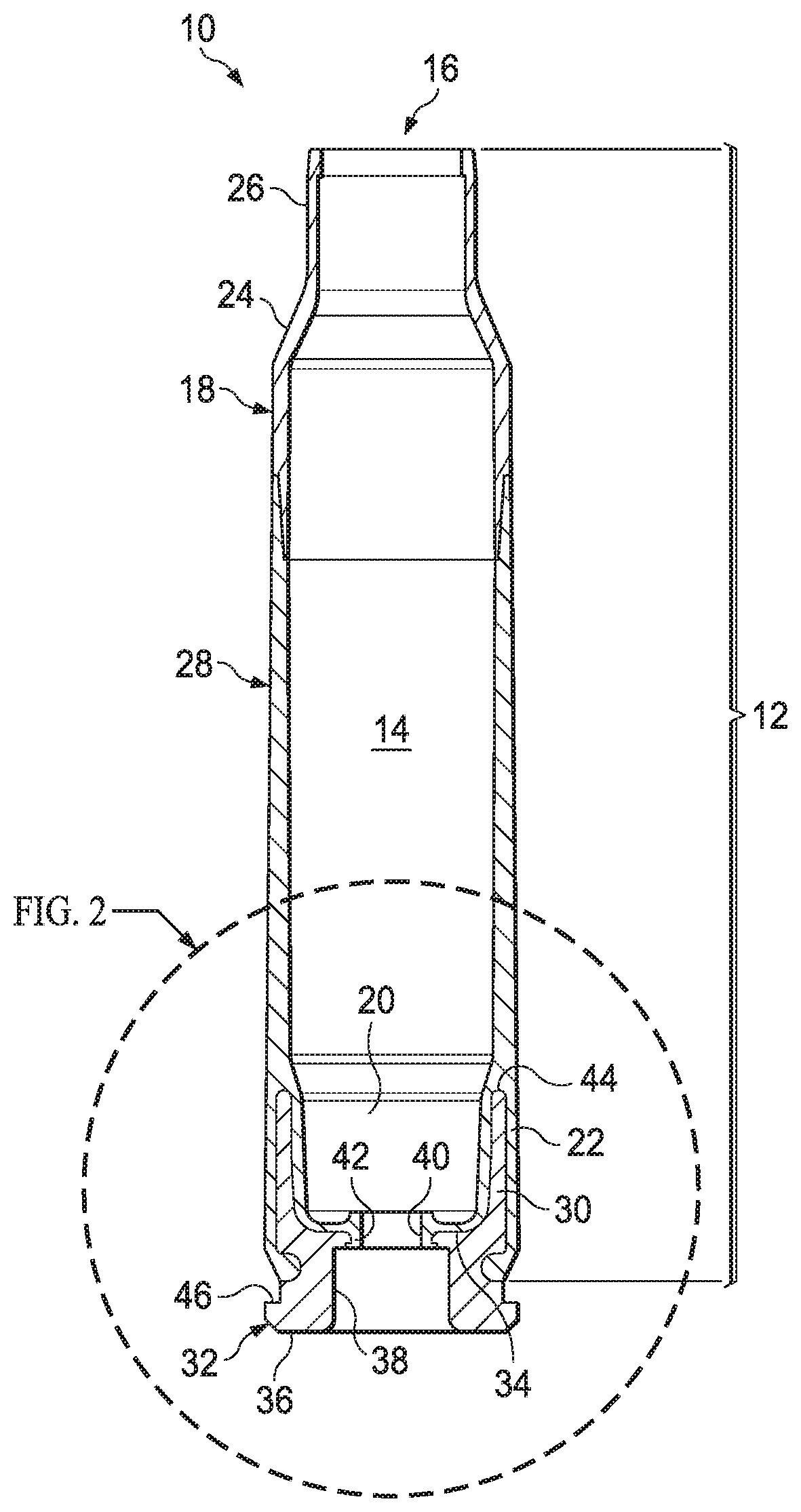
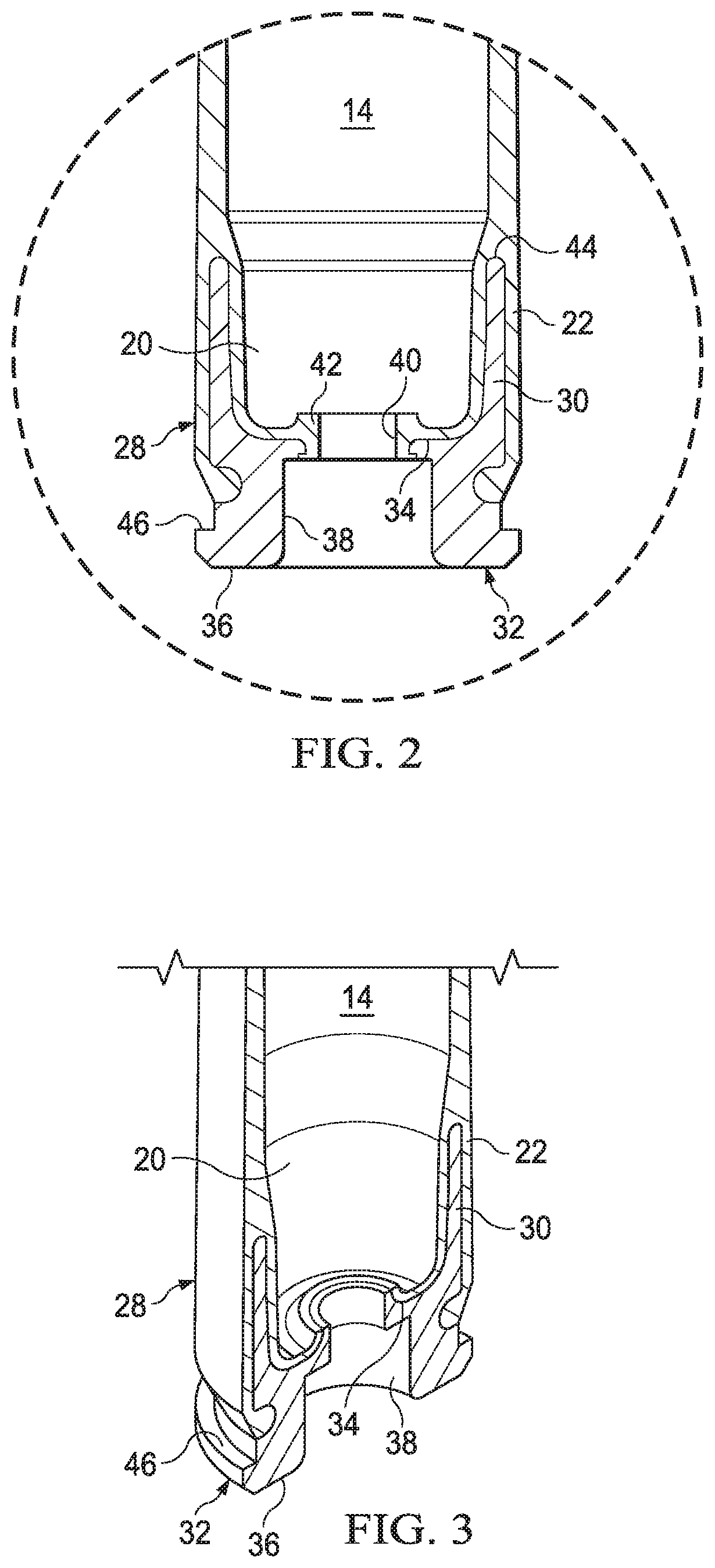
[0012] FIG. 2 depicts a side, cross-sectional view of a portion of the polymeric cartridge case according to one embodiment of the present invention;
[0013] FIG. 3 depicts a side, cross-sectional view of a portion of the polymeric cartridge casing lacking the aperture coating;
[0014] FIG. 4 is a top plan view of a general primer;
[0015] FIG. 5 depicts a cross-sectional elevation view taken along line 2-2 of the primer in FIG. 4;
[0016] FIGS. 6a and 6b are images of a diffuser adapter;
[0017] FIG. 7 is an exploded image of the diffuser ring that is placed between the primer and the bottom of the primer recess;
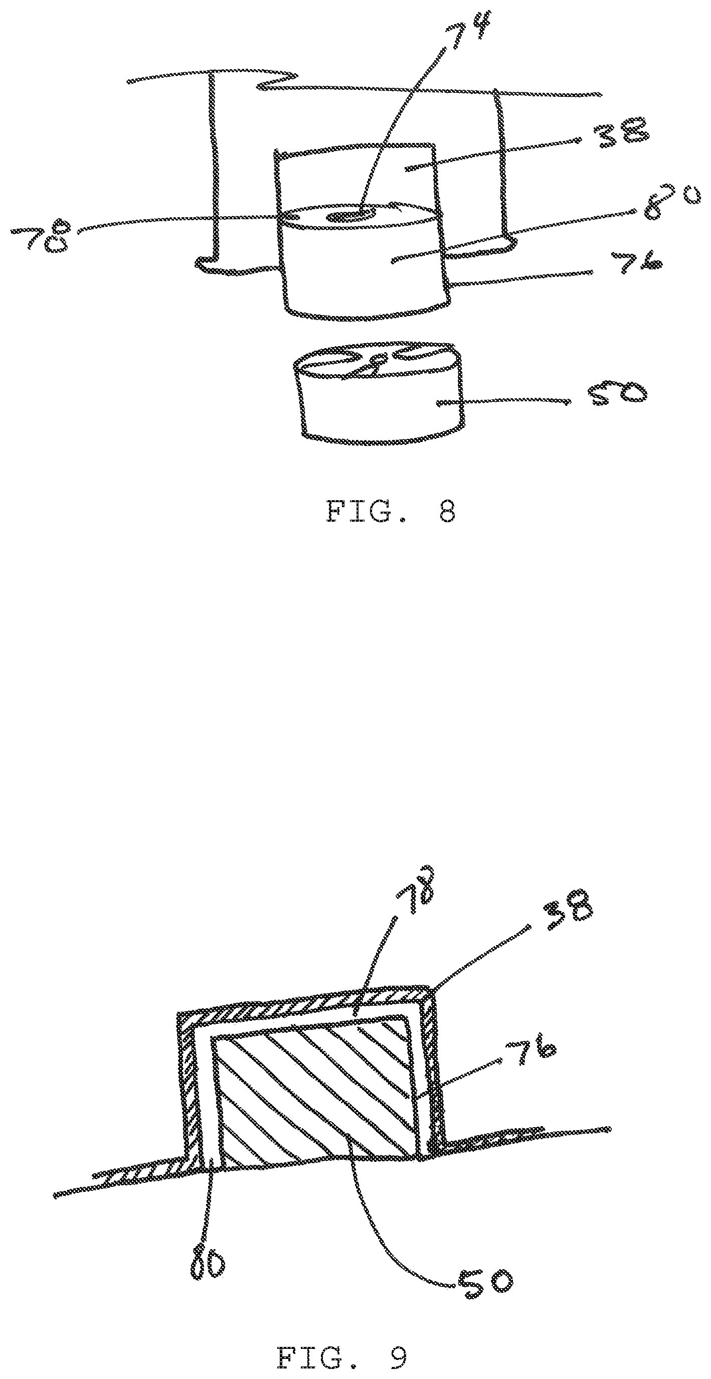
[0018] FIG. 8 is an exploded image of the diffuser cup that at least partially covers the primer and fits in the primer recess; and
[0019] FIG. 9 is a cut away image of the diffuser cup that at least partially covers the primer and fits in the primer recess.
DETAILED DESCRIPTION OF THE INVENTION
[0020] While the making and using of various embodiments of the present invention are discussed in detail below, it should be appreciated that the present invention provides many applicable inventive concepts that can be embodied in a wide variety of specific contexts. The specific embodiments discussed herein are merely illustrative of specific ways to make and use the invention and do not delimit the scope of the invention.
[0021] To facilitate the understanding of this invention, a number of terms are defined below. Terms defined herein have meanings as commonly understood by a person of ordinary skill in the areas relevant to the present invention. Terms such as "a", "an" and "the" are not intended to refer to only a singular entity, but include the general class of which a specific example may be used for illustration. The terminology herein is used to describe specific embodiments of the invention, but their usage does not delimit the invention, except as outlined in the claims.
[0022] As used herein, the term "ammunition", "ammunition article", "munition", and "munition article" as used herein may be used interchangeably to refer to a complete, assembled round or cartridge that is ready to be loaded into a firearm and fired, including cap, casing, propellant, projectile, etc. Ammunition may be a live round fitted with a projectile, or a blank round with no projectile and may also be other types such as non-lethal rounds, rounds containing rubber bullets, rounds containing multiple projectiles (shot), and rounds containing projectiles other than bullets such as fluid-filled canisters and capsules. Ammunition may be any caliber of pistol or rifle ammunition, e.g., non limiting examples include .22, .22-250, .223, .243, .25-06, .270, .300, .30-30, .30-40, 30.06, .300, .303, .308, .338, .357, .38, .380, .40, .44, .45, .45-70, .50 BMG, 5.45 mm, 5.56 mm, 6.5 mm, 6.8 mm, 7 mm, 7.62 mm, 8 mm, 9 mm, 10 mm, 12.7 mm, 14.5 mm, 20 mm, 25 mm, 30 mm, 40 mm and others.
[0023] As used herein, the term "casing" and "case" and "body" are used interchangeably (e.g., "cartridge casing", "cartridge case" and "casing body") to refer to the portion of the ammunition that remains intact after firing and includes the propellant chamber and may include the primer insert. A cartridge casing may be one-piece, two-piece, three piece or multi-piece design that includes a mouth at one end and a primer insert at the other separated by a propellant chamber.
[0024] The polymeric ammunition cartridges of the present invention are of a caliber typically carried by soldiers in combat for use in their combat weapons. The present invention is not limited to the described caliber and is believed to be applicable to other calibers as well. This includes various small and medium caliber munitions, including 5.56 mm, 7.62 mm and .50 caliber ammunition cartridges, as well as medium/small caliber ammunition such as 380 caliber, 38 caliber, 9 mm, 10 mm, 20 mm, 25 mm, 30 mm, 40 mm, 45 caliber and the like. The cartridges, therefore, are of a caliber between about 0.05 and about 5 inches. Thus, the present invention is also applicable to the sporting goods industry for use by hunters and target shooters.
[0025] A traditional cartridge casing generally has a deep-drawn elongated body with a primer end and a projectile end. During use, a weapon's cartridge chamber supports the majority of the cartridge casing wall in the radial direction, however, in many weapons, a portion of the cartridge base end is unsupported. During firing, the greatest stresses are concentrated at the base end of the cartridge, which must have great mechanical strength. This is true for both subsonic and supersonic ammunition cartridges.
[0026] Reliable cartridge manufacture requires uniformity from one cartridge to the next in order to obtain consistent ballistic performance. Among other considerations, proper bullet seating and bullet-to-casing fit is required. In this manner, a desired pressure develops within the casing during firing prior to bullet and casing separation. Historically, bullets employ a cannelure, which is a slight annular depression formed in a surface of the bullet at a location determined to be the optimal seating depth for the bullet. In this manner, a visual inspection of a cartridge could determine whether or not the bullet is seated at the proper depth. Once the bullet is inserted into the casing to the proper depth, one of two standard procedures is incorporated to lock the bullet in its proper location. One method is the crimping of the entire end of the casing into the cannelure. A second method does not crimp the casing end; rather the bullet is pressure fitted into the casing.
[0027] Firing pin-initiated primers are employed in ammunition primarily for initiation of the powder charge. A firing pin-initiated primer or percussion cap consists of a pressed or cast impact-sensitive charge of a known type, a so-called anvil which abuts against the sides of the primer charge which face in the initiation direction thereof, that is towards the main or propellant charge which is to be initiated by the primer, and a protective case or capsule surrounding the other sides of the primer charge and consisting of at least partly deformable material. The surface of the primer charge facing the anvil may also be covered by a readily destructible protective foil which, as a rule, mainly has a moisture-protective function. On the initiation of the primer, the casing is, thus, to be deformed by a firing pin opposite the anvil, so that the primer charge which is compressed between the anvil and the deformed case, is initiated. In the primer designs most commonly employed today, the anvil consists of a bent sheet bridge with gaps on either side thereof in order that the flame jets from the initiated primer charge will be able to reach the main or propellant charge. The anvil consists of a metal body perforated by some means for the passage of the flame jets. The drawback inherent in both of these basic types of anvil is that they leave greater or smaller parts of the upper surface of the primer charge wholly without support, either in the form of gaps beside the anvil or perforations through the anvil.
[0028] The present invention is a diffuser that adapts a primer to a polymer cartridge. Generally, the ammunition cartridge includes a polymer cartridge that has been overmolded over a metal primer insert that includes a primer recess. The present diffuser is adapted to fit between the primer recess and abut the interior wall of the primer recess to separate the primer from the bottom wall of the primer recess. In another embodiment, the diffuser is adapted to fit in the primer recess and abut both the side wall and the bottom wall of the primer recess to separate the primer from the walls of the primer recess.
[0029] FIG. 1 depicts an exploded view of the polymeric cartridge casing. A cartridge 10 is shown with a polymer casing 12 showing a propellant chamber 14 with a forward end opening 16 for insertion of a projectile (not shown). Polymer casing 12 has a substantially cylindrical open-ended polymeric bullet-end component 18 extending from forward end opening 16 rearward to opposite end 20. The bullet-end component 18 may be formed with coupling end 22 formed on opposite end 20. Coupling end 22 is shown as a female element, but may also be configured as a male element in alternate embodiments of the invention. The forward end of polymeric bullet-end component 18 has a shoulder 24 forming chamber neck 26. Polymer casing 12 has a substantially cylindrical opposite end 20. Coupling end 22 is shown as a female element, but may also be configured as a male element in alternate embodiments of the invention. The middle body component (not shown) is connected to a substantially cylindrical coupling element 30 of the substantially cylindrical insert 32. Coupling element 30, as shown may be configured as a male element, however, all combinations of male and female configurations is acceptable for coupling elements 30 and coupling end 22 in alternate embodiments of the invention. Coupling end 22 fits about and engages cylindrical coupling element 30 of a substantially cylindrical insert 32. The substantially cylindrical insert 32 includes a substantially cylindrical coupling element 30 extending from a bottom surface 34 that is opposite a top surface 36. When contacted the coupling end 22 interlocks with the substantially cylindrical coupling element 30, through the coupling element 30 that extends with a taper to a smaller diameter at the tip 44 to form a physical interlock between substantially cylindrical insert 32 and middle body component 28. The substantially cylindrical insert 32 also has a flange 46 cut therein and a primer recess 38 and primer flash hole aperture 42 formed therein for ease of insertion of the primer (not shown). A primer flash hole aperture 42 is located in the primer recess 38 and extends through the bottom surface 34 into the propellant chamber 14 to combust the propellant in the propellant chamber 14. When molded the coupling end 22 extends the polymer through the primer flash hole aperture 42 to form the primer flash hole 40 while retaining a passage from the top surface 36 through the bottom surface 34 and into the propellant chamber 14 to provide support and protection about the primer flash hole aperture 42.
[0030] FIG. 2 depicts a side, cross-sectional view of a portion of the polymeric cartridge case according to one embodiment of the present invention. A portion of a cartridge suitable for use with high velocity rifles is shown manufactured with a polymer casing 12 showing a propellant chamber 14. Polymer casing 12 has a substantially cylindrical opposite end 20. The bullet-end component 18 may be formed with coupling end 22 formed on opposite end 20. Cylindrical coupling end 22 is shown as a female element, but may also be configured as a male element in alternate embodiments of the invention. The middle body component (not shown) is connected to a substantially cylindrical coupling element 30 of the substantially cylindrical insert 32. Coupling element 30, as shown may be configured as a male element, however, all combinations of male and female configurations is acceptable for coupling elements 30 and coupling end 22 in alternate embodiments of the invention. Coupling end 22 fits about and engages coupling element 30 of a substantially cylindrical insert 32. The substantially cylindrical insert 32 includes a substantially cylindrical coupling element 30 extending from a bottom surface 34 that is opposite a top surface 36. Located in the top surface 36 is a primer recess 38 that extends toward the bottom surface 34. A primer flash hole 40 is located in the primer recess 38 and extends through the bottom surface 34 into the propellant chamber 14. The coupling end 22 extends the polymer through the primer flash hole 40 to form a flash hole aperture 42 while retaining a passage from the top surface 36 through the bottom surface 34 and into the propellant chamber 14 to provide support and protection about the primer flash hole 40. When contacted the coupling end 22 interlocks with the substantially cylindrical coupling element 30, through the cylindrical coupling element 30 that extends with a taper to a smaller diameter at the tip 44 to form a physical interlock between substantially cylindrical insert 32 and middle body component 28. Polymer casing 12 also has a substantially cylindrical open-ended middle body component 28.
[0031] FIG. 3 depicts a side, cross-sectional view of a portion of the polymeric cartridge case lacking the aperture coating (not shown). A portion of a cartridge suitable for use with high velocity rifles is shown manufactured with a polymer casing 12 showing a propellant chamber 14. Polymer casing 12 has a substantially cylindrical opposite end 20. The polymer bullet-end component 18 may be formed with coupling end 22 formed on opposite end 20. Coupling end 22 is shown as a female element, but may also be configured as a male element in alternate embodiments of the invention. The middle body component (not shown) is connected to a substantially cylindrical coupling element 30 of the substantially cylindrical insert 32. Coupling element 30, as shown may be configured as a male element, however, all combinations of male and female configurations is acceptable for coupling elements 30 and coupling end 22 in alternate embodiments of the invention. Coupling end 22 fits about and engages coupling element 30 of a substantially cylindrical insert 32. The substantially cylindrical insert 32 includes a substantially cylindrical coupling element 30 extending from a bottom surface 34 that is opposite a top surface 36. Located in the top surface 36 is a primer recess 38 that extends toward the bottom surface 34. A primer flash hole 40 is located in the primer recess 38 and extends through the bottom surface 34 into the propellant chamber 14. The coupling end 22 extends the polymer through the primer flash hole 40 to form a primer flash hole aperture coating 42 while retaining a passage from the top surface 36 through the bottom surface 34 and into the propellant chamber 14 to provide support and protection about the primer flash hole 40. When contacted the coupling end 22 interlocks with the substantially cylindrical coupling element 30, through the coupling element 30 that extends with a taper to a smaller diameter at the tip 44 to form a physical interlock between substantially cylindrical insert 32 and middle body component 28. Polymer casing 12 also has a substantially cylindrical open-ended middle body component 28.
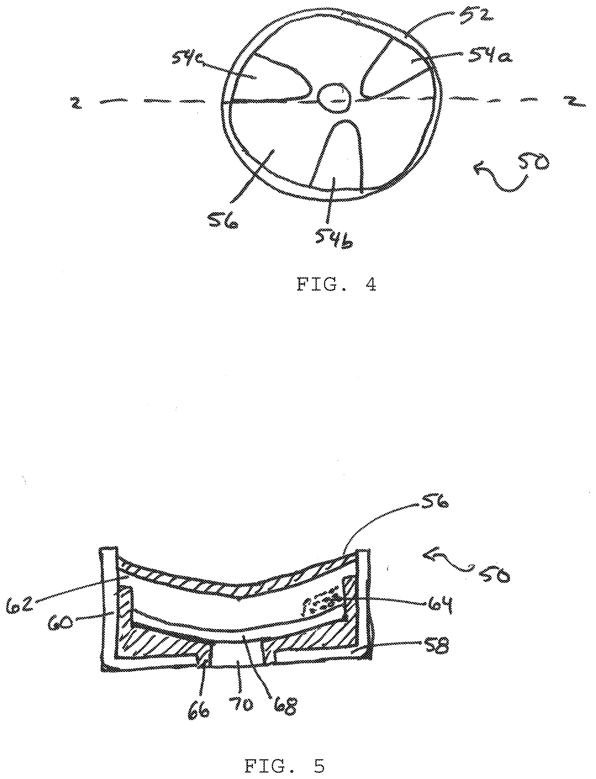
[0032] FIG. 4 depicts a top view of a primer 50. The primer 50 includes the cup 52 having a retaining means 54a, 54b and 54c and anvil 56.
[0033] FIG. 5 depicts a cross-sectional elevation view taken along line 2-2 of the primer 50 in FIG. 4. The primer 50 includes the cup 52 having a bottom 58 and side wall 60 that forms an internal cavity 62 that houses an explosive charge 64. The cup 52 is sized to frictionally fit a primer aperture (not shown). An insulating liner 66 is positioned within the cup 50 separating the cup 50 from the contact 68. A button 70 is positioned in the bottom 58 surrounded by the insulating liner 66 and contacting the contact 68. When a firing pin strikes the primer 50 and crushed the button 70 against the anvil 56, the highly reactive explosive charge is initiated by the button 70 to produce a high velocity flame that extends into the flash hole (not shown) and contacts the propellant (not shown). This is only one embodiment of a primer 50 that may be used with the present invention and any primer 50 may be used.
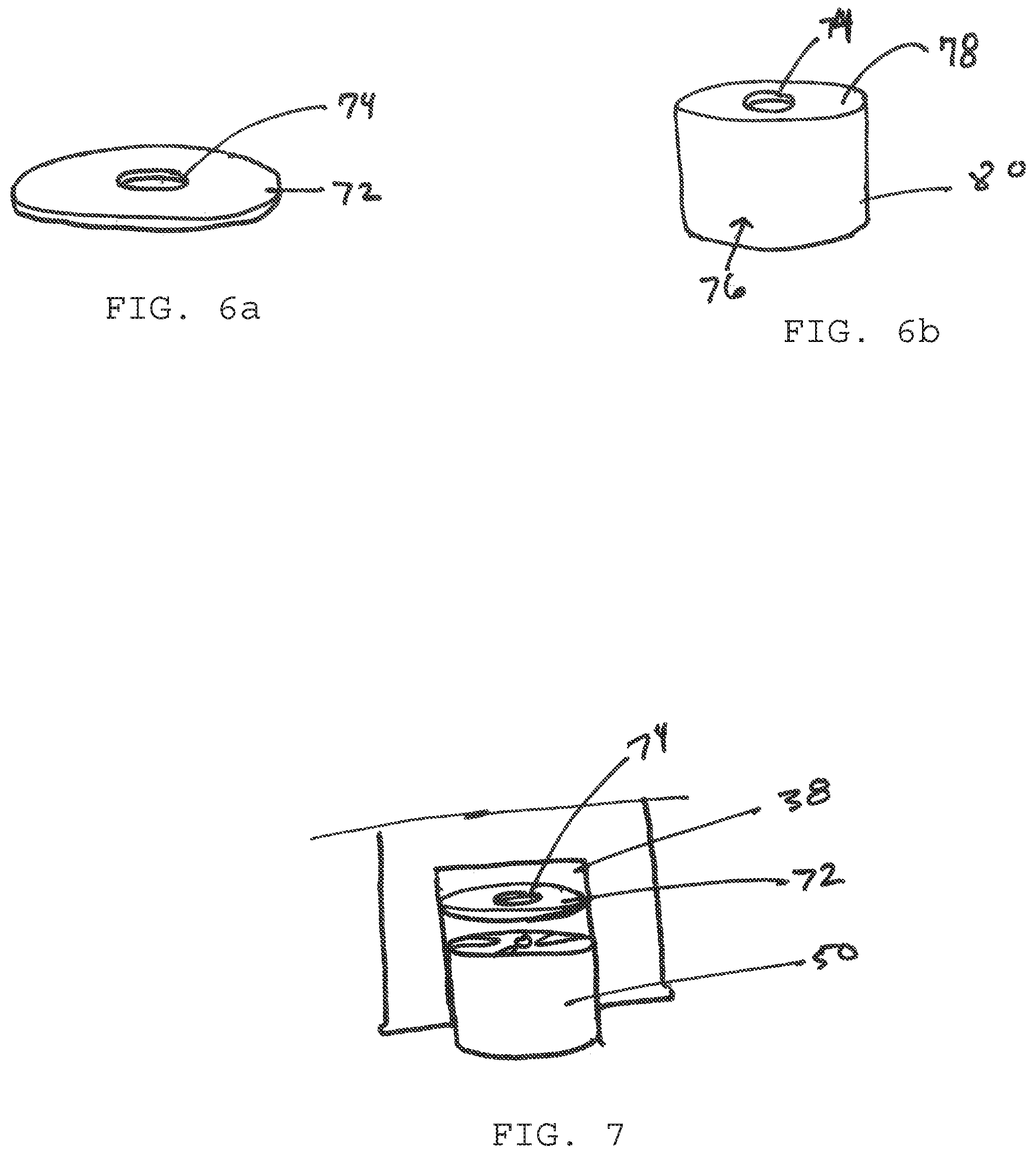
[0034] FIGS. 6a and 6b are images of a diffuser adapter. FIG. 6a is an image of a diffuser ring 72 that is placed between the primer (not shown) and the bottom of the primer recess (not shown). The diffuser ring 72 includes a diffuser aperture 74 that aligns with the flash hole (not shown) and the primer (not shown). FIG. 6b is an image of a diffuser cup 76 that covers (or at least partially covers) the primer (not shown) and fits in the primer recess (not shown). The diffuser cup 76 includes bottom surface 78 that includes a diffuser aperture 74 that aligns with the flash hole (not shown) and a cup wall 80 that attaches to the bottom surface 78 to cover the primer (not shown).
[0035] FIG. 7 is an exploded image of the diffuser ring 72 that is placed between the primer 50 and the bottom of the primer recess 38. The diffuser ring 72 includes a diffuser aperture 74 that aligns with the flash hole (not shown) and the primer 50.
[0036] FIG. 8 is an exploded image of the diffuser cup 76 that covers (or at least partially covers) the primer 50 and fits in the primer recess 38. The diffuser cup 76 includes bottom surface 78 that includes a diffuser aperture 74 that aligns with the flash hole (not shown) of the primer recess 38. The diffuser cup 76 includes a cup wall 80 that attaches to the bottom surface 78 to cover the primer 50.
[0037] FIG. 9 is a cut away image of the diffuser cup 76 that covers (or at least partially covers) the primer 50 and fits in the primer recess 38. The diffuser cup 76 includes bottom surface 78 that includes a diffuser aperture 74 that aligns with the flash hole (not shown) of the primer recess 38. The diffuser cup 76 includes a cup wall 80 that attaches to the bottom surface 78 to cover the primer 50. The diffuser cup 76 and the diffuser ring 72 may be made of a metal or alloy or a polymer composition and may be combined with some form of suitable sealant. This seal may possibly be improved by a sealant or by pressing the anvil against the diffuser cup or the diffuser ring.
[0038] The components may be formed from high-strength polymer, composite metal, alloys or ceramic. Examples of suitable high strength polymers include composite polymer materials including a tungsten metal powder, nylon 6/6, nylon 6, and glass fibers; and a specific gravity in a range of 3-10. The tungsten metal powder may be 50%-96% weight. The polymer material also includes about 0.5-15%, preferably about 1-12%, and most preferably about 2-9% by weight, of nylon 6/6, about 0.5-15%, preferably about 1-12%, and most preferably about 2-9% by weight, of nylon 6, and about 0.5-15%, preferably about 1-12%, and most preferably about 2-9% by weight, of glass fibers. It is most suitable that each of these ingredients be included in amounts less than 10% by weight. The composition may be made of a modified ZYTEL.RTM. resin, available from E.I. DuPont De Nemours Co., a modified 612 nylon resin, modified to increase elastic response. Examples of suitable polymers include polyurethane prepolymer, cellulose, fluoro-polymer, ethylene inter-polymer alloy elastomer, ethylene vinyl acetate, nylon, polyether imide, polyester elastomer, polyester sulfone, polyphenyl amide, polypropylene, polyvinylidene fluoride or thermoset polyurea elastomer, acrylics, homopolymers, acetates, copolymers, acrylonitrile-butadinen-styrene, thermoplastic fluoro polymers, inomers, polyamides, polyamide-imides, polyacrylates, polyatherketones, polyaryl-sulfones, polybenzimidazoles, polycarbonates, polybutylene, terephthalates, polyether imides, polyether sulfones, thermoplastic polyimides, thermoplastic polyurethanes, polyphenylene sulfides, polyethylene, polypropylene, polysulfones, polyvinylchlorides, styrene acrylonitriles, polystyrenes, polyphenylene, ether blends, styrene maleic anhydrides, polycarbonates, allyls, aminos, cyanates, epoxies, phenolics, unsaturated polyesters, bismaleimides, polyurethanes, silicones, vinylesters, or urethane hybrids. Examples of suitable polymers also include aliphatic or aromatic polyamide, polyeitherimide, polysulfone, polyphenylsulfone, poly-phenylene oxide, liquid crystalline polymer and polyketone. Examples of suitable composites include polymers such as polyphenylsulfone reinforced with between about 30 and about 70 weight percent, and preferably up to about 65 weight percent of one or more reinforcing materials selected from glass fiber, ceramic fiber, carbon fiber, mineral fillers, organo nanoclay, or carbon nanotube. Preferred reinforcing materials, such as chopped surface-treated E-glass fibers provide flow characteristics at the above-described loadings comparable to unfilled polymers to provide a desirable combination of strength and flow characteristics that permit the molding of head-end components. Composite components can be formed by machining or injection molding. Finally, the cartridge case must retain sufficient joint strength at cook-off temperatures. More specifically, polymers may have one or more of the following properties: Yield or tensile strength at -65.degree. F.>10,000 psi Elongation-to-break at -65.degree. F.>15% Yield or tensile strength at 73.degree. F.>8,000 psi Elongation-to-break at 73.degree. F.>50% Yield or tensile strength at 320.degree. F.>4,000 psi Elongation-to-break at 320.degree. F.>80%. Commercially available polymers suitable for use in the present invention thus include polyphenylsulfones; copolymers of polyphenylsulfones with polyether-sulfones or polysulfones; copolymers and blends of polyphenylsulfones with polysiloxanes; poly(etherimide-siloxane); copolymers and blends of polyetherimides and polysiloxanes, and blends of polyetherimides and poly(etherimide-siloxane) copolymers; and the like. Particularly preferred are polyphenylsulfones and their copolymers with poly-sulfones or polysiloxane that have high tensile strength and elongation-to-break to sustain the deformation under high interior ballistic pressure. Such polymers are commercially available, for example, RADEL.RTM. R5800 polyphenylesulfone from Solvay Advanced Polymers. The polymer can be formulated with up to about 10 wt % of one or more additives selected from internal mold release agents, heat stabilizers, anti-static agents, colorants, impact modifiers and UV stabilizers.
[0039] One of ordinary skill in the art will know that many propellant types and weights can be used to prepare workable ammunition and that such loads may be determined by a careful trial including initial low quantity loading of a given propellant and the well known stepwise increasing of a given propellant loading until a maximum acceptable load is achieved. Extreme care and caution is advised in evaluating new loads. The propellants available have various burn rates and must be carefully chosen so that a safe load is devised.
[0040] The description of the preferred embodiments should be taken as illustrating, rather than as limiting, the present invention as defined by the claims. As will be readily appreciated, numerous combinations of the features set forth above can be utilized without departing from the present invention as set forth in the claims. Such variations are not regarded as a departure from the spirit and scope of the invention, and all such modifications are intended to be included within the scope of the following claims.
[0041] It is contemplated that any embodiment discussed in this specification can be implemented with respect to any method, kit, reagent, or composition of the invention, and vice versa. Furthermore, compositions of the invention can be used to achieve methods of the invention.
[0042] It will be understood that particular embodiments described herein are shown by way of illustration and not as limitations of the invention. The principal features of this invention can be employed in various embodiments without departing from the scope of the invention. Those skilled in the art will recognize, or be able to ascertain using no more than routine experimentation, numerous equivalents to the specific procedures described herein. Such equivalents are considered to be within the scope of this invention and are covered by the claims.
[0043] All publications and patent applications mentioned in the specification are indicative of the level of skill of those skilled in the art to which this invention pertains. All publications and patent applications are herein incorporated by reference to the same extent as if each individual publication or patent application was specifically and individually indicated to be incorporated by reference.
[0044] The use of the word "a" or "an" when used in conjunction with the term "comprising" in the claims and/or the specification may mean "one," but it is also consistent with the meaning of "one or more," "at least one," and "one or more than one." The use of the term "or" in the claims is used to mean "and/or" unless explicitly indicated to refer to alternatives only or the alternatives are mutually exclusive, although the disclosure supports a definition that refers to only alternatives and "and/or." Throughout this application, the term "about" is used to indicate that a value includes the inherent variation of error for the device, the method being employed to determine the value, or the variation that exists among the study subjects.
[0045] As used in this specification and claim(s), the words "comprising" (and any form of comprising, such as "comprise" and "comprises"), "having" (and any form of having, such as "have" and "has"), "including" (and any form of including, such as "includes" and "include") or "containing" (and any form of containing, such as "contains" and "contain") are inclusive or open-ended and do not exclude additional, unrecited elements or method steps.
[0046] The term "or combinations thereof" as used herein refers to all permutations and combinations of the listed items preceding the term. For example, "A, B, C, or combinations thereof" is intended to include at least one of: A, B, C, AB, AC, BC, or ABC, and if order is important in a particular context, also BA, CA, CB, CBA, BCA, ACB, BAC, or CAB. Continuing with this example, expressly included are combinations that contain repeats of one or more item or term, such as BB, AAA, AB, BBC, AAABCCCC, CBBAAA, CABABB, and so forth. The skilled artisan will understand that typically there is no limit on the number of items or terms in any combination, unless otherwise apparent from the context.
* * * * *
D00000
D00001
D00002
D00003
D00004
D00005
XML
uspto.report is an independent third-party trademark research tool that is not affiliated, endorsed, or sponsored by the United States Patent and Trademark Office (USPTO) or any other governmental organization. The information provided by uspto.report is based on publicly available data at the time of writing and is intended for informational purposes only.
While we strive to provide accurate and up-to-date information, we do not guarantee the accuracy, completeness, reliability, or suitability of the information displayed on this site. The use of this site is at your own risk. Any reliance you place on such information is therefore strictly at your own risk.
All official trademark data, including owner information, should be verified by visiting the official USPTO website at www.uspto.gov. This site is not intended to replace professional legal advice and should not be used as a substitute for consulting with a legal professional who is knowledgeable about trademark law.