Cold Box Structure With Cold Box Panels Partly Built-in And Installation Method Therefor
BRIGLIA; Alain ; et al.
U.S. patent application number 16/610205 was filed with the patent office on 2020-02-20 for cold box structure with cold box panels partly built-in and installation method therefor. This patent application is currently assigned to L'Air Liquide, Societe Anonyme pour I'Etude et I'Exploitation des Procedes Georges Claude. The applicant listed for this patent is Alain BRIGLIA, Remy KURTZ, L'Air Liquide, Societe Anonyme pour I'Etude et I'Exploitation des Procedes Georges Claude. Invention is credited to Alain BRIGLIA, Remy KURTZ.
| Application Number | 20200056840 16/610205 |
| Document ID | / |
| Family ID | 64015750 |
| Filed Date | 2020-02-20 |


| United States Patent Application | 20200056840 |
| Kind Code | A1 |
| BRIGLIA; Alain ; et al. | February 20, 2020 |
COLD BOX STRUCTURE WITH COLD BOX PANELS PARTLY BUILT-IN AND INSTALLATION METHOD THEREFOR
Abstract
Disclosed are a cold box structure with cold box panels partly built-in and an installation method therefor. The cold box structure is mainly applied to plate-fin heat exchangers, and in particular to high-pressure aluminum plate-fin heat exchangers. The cold box structure comprises a base, a cold box support frame, four cold box panels, and a cold box top plate, and a plate-fin heat exchanger is placed inside the cold box. Some of or all the four cold box panels can be placed inside the cold box support frame as needed. The cold box structure can protect the cold box support frame from being damaged by cryogenic steam ejected from the plate fin-heat exchanger due to leakage, and further enables the discovering of leakage situations of the plate-fin heat exchanger from outer surfaces of the cold box panels in a timely manner.
| Inventors: | BRIGLIA; Alain; (Hangzhou, CN) ; KURTZ; Remy; (Hangzhou, CN) | ||||||||||
| Applicant: |
|
||||||||||
|---|---|---|---|---|---|---|---|---|---|---|---|
| Assignee: | L'Air Liquide, Societe Anonyme pour
I'Etude et I'Exploitation des Procedes Georges Claude Paris FR |
||||||||||
| Family ID: | 64015750 | ||||||||||
| Appl. No.: | 16/610205 | ||||||||||
| Filed: | May 3, 2017 | ||||||||||
| PCT Filed: | May 3, 2017 | ||||||||||
| PCT NO: | PCT/CN2017/082891 | ||||||||||
| 371 Date: | November 1, 2019 |
| Current U.S. Class: | 1/1 |
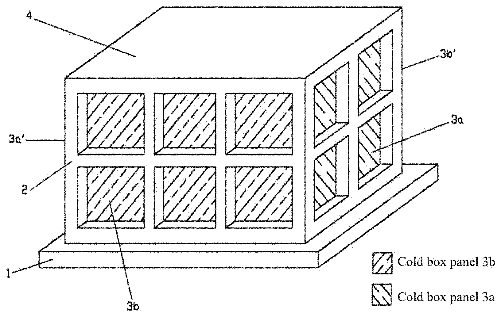
| Current CPC Class: | F28F 3/02 20130101; F25J 3/04854 20130101; E04H 5/10 20130101; F25J 3/04945 20130101; F25D 3/102 20130101 |
| International Class: | F25J 3/04 20060101 F25J003/04; E04H 5/10 20060101 E04H005/10; F28F 3/02 20060101 F28F003/02; F25D 3/10 20060101 F25D003/10 |
Claims
1-6. (canceled)
7. A cold box structure comprising a cold box support frame, four cold box panels, a base and a cold box top plate, a plate-fin heat exchanger being placed inside the cold box support frame, and perlite sand being filled between the cold box and the plate-fin heat exchanger, characterized in that the cold box panels facing seals of the plate-fin heat exchanger are located inside the cold box support frame.
8. The cold box structure as claimed in to claim 7, wherein the cold box support frame and the cold box panels are made of carbon steel or stainless steel.
9. The cold box structure as claimed in to claim 7, wherein the cold box panels facing lateral plates of the plate-fin heat exchanger are located outside the cold box support frame on sides.
10. The cold box structure as claimed in to claim 7, wherein the cold box panels facing lateral plates of the plate-fin heat exchanger are located inside the cold box support frame on sides.
11. An installation method applicable to the cold box structure of claim 7, the method comprising the steps of: a. affixing a cold box base, installing a cold box support frame, and installing a plate-fin heat exchanger inside the cold box support frame; b. installing four cold box panels, wherein the cold box panels facing seals of the plate-fin heat exchanger are installed inside the cold box support frame on sides, and the cold box panels facing lateral plates of the plate-fin heat exchanger are installed inside or outside the cold box support frame on sides; c. installing a cold box top plate at the top of the cold box support frame; and d. welding the parts of the cold box in a sealed manner, filling the cold box with perlite sand.
12. The installation method as claimed in claim 11, wherein the cold box panels facing the seals of the plate-fin heat exchanger are installed in advance inside the cold box support frame on the sides.
13. The installation method as claimed in claim 11, wherein the cold box panels facing the seals of the plate-fin heat exchanger are installed on-site inside the cold box support frame on the sides.
14. The installation method as claimed in claim 11, wherein step d further comprises charging the cold box with nitrogen after filling the cold box with perlite sand.
Description
CROSS REFERENCE TO RELATED APPLICATIONS
[0001] This application is a .sctn. 371 of International PCT Application PCT/CN2017/082891, filed May 3, 2017, which is herein incorporated by reference in its entirety.
TECHNICAL FIELD
[0002] The present invention relates to a cold box structure for a plate-fin heat exchanger and an installation method therefor, which are particularly suitable for a high-pressure aluminum plate-fin heat exchanger.
BACKGROUND ART
[0003] The plate-fin heat exchanger has the characteristics of compact structure, light weight, high heat transfer efficiency, etc., and so is widely used in industrial sectors such as refrigeration, petrochemical, air separation, aerospace, power machinery and superconducting, and is generally recognized as one of the new efficient heat exchangers. Due to the low-temperature ductility and good tensile properties of aluminum alloy, plate-fin heat exchangers made of aluminum alloy are particularly suitable for low-temperature and ultra-low-temperature applications, and are also widely used in air separation processes in modern industries. At present, almost all the heat exchangers of air separation apparatuses use plate-fin heat exchangers. Due to operating at a temperature below -150.degree. C., the air separation apparatus needs to be placed inside a cold box, and the cold box is filled with perlite sand to provide heat insulation.
[0004] Generally, the cold box is in the shape of a rectangular hexahedron, comprising a base, a cold box support frame, four cold box panels and a cold box top plate. In the prior art, the cold box panels are welded to the outer side the cold box support frame. The cold box can be made of carbon steel or stainless steel, but due to the high price of stainless steel, carbon steel is usually used in practice. However, the carbon steel material is prone to brittle fracture at low temperatures. In the process of air separation, if leakage occurs at a plate-fin heat exchanger and low-temperature steam is ejected, the perlite sand inside the cold box becomes damp and hardened, and the cold box panels or the cold box support frame of carbon steel is easily damaged. Failure to timely discover leakage may result in other serious consequences.
[0005] In traditional cold box structures, the cold box panels are placed outside the cold box support frame structure. In the process of air separation, cryogenic steam is ejected if leakage occurs at the plate-fin heat exchanger. If the leaked steam is directly ejected to the cold box support frame, since the cold box panels are located outside the cold box support frame and shield the cold box support frame, the damage caused by the leakage is not easily discovered in a timely manner, which may result in the failure to timely discover leakage in the plate-fin heat exchanger. This is not conducive to the safe operation of air separation systems, resulting in degraded quality of air separation products, which also may cause serious safety accidents; in addition, the repair work for the damaged cold box support frame is huge and the cost is high.
SUMMARY OF THE INVENTION
[0006] Certain embodiments of the present invention provide a cold box structure with cold box panels partly built-in, which is applicable to a plate-fin heat exchanger, and in particular to a high-pressure aluminum plate-fin heat exchanger for use in an air separation process. The cold box of a carbon steel material in certain embodiments of the present invention is especially applicable to brazed aluminum plate-fin heat exchangers with the working pressure higher than 20 bar. Since leakage easily occurs on the sides of the high-pressure plate-fin heat exchanger where seals are located, and the temperature at the cold end of the heat exchanger is -196.degree. C., cryogenic steam ejected due to leakage seriously damages the carbon steel structure, and brittle fracture, etc. may occur. In certain embodiments of the present invention, cold box panels facing sides of the plate-fin heat exchanger where the seals are located are placed inside the cold box support frame, so that the leakage can be timely discovered from the frost and icing conditions of the cold box panels upon occurring, which has the function of protecting the cold box support frame.
[0007] The technical solution adopted by at least one embodiment of the present invention to solve the above technical problems is:
[0008] a cold box structure comprising a base, a cold box support frame, four cold box panels and a cold box top plate, a plate-fin heat exchanger being fixed inside the cold box, wherein the cold box panels facing sides of the plate-fin heat exchanger where seals are located are placed inside the cold box support frame, and perlite sand is filled between the cold box and the plate-fin heat exchanger.
[0009] In the present invention, the cold box support frame, the cold box panels, and the cold box top plate may be made of carbon steel or stainless steel.
[0010] In another embodiment of the present invention, the cold box panels facing sides of the plate-fin heat exchanger where lateral plates are located are placed outside the cold box support frame, and may also be placed inside the cold box support frame.
[0011] An installation method for the cold box structure can include the steps of:
[0012] 1) affixing a cold box base, installing a cold box support frame, and installing a plate-fin heat exchanger inside the cold box support frame;
[0013] 2) installing four cold box panels, wherein the cold box panels facing seals of the plate-fin heat exchanger are installed inside the cold box support frame, and the cold box panels facing lateral plates of the plate-fin heat exchanger are installed inside or outside the cold box support frame;
[0014] 3) installing a cold box top plate at the top of the cold box support frame; and
[0015] 4) welding the parts of the cold box in a sealed manner, filling the cold box with perlite sand, and, if necessary, charging nitrogen.
[0016] In step 2) of the installation method, the cold box panels facing the seals of the plate-fin heat exchanger are installed in advance inside the cold box support frame, or are installed on-site inside the cold box support frame, depending on the on-site installation size.
[0017] The positive effects produced by the technical solution of the present invention are as follows:
[0018] 1) The cold box support frame is protected. When leakage occurs at the plate-fin heat exchanger, the leaked steam is prevented from being directly ejected to the cold box support frame, thereby protecting the cold box support frame from being damaged.
[0019] 2) The leakage situation is timely discovered. The cold box panels facing the sides of the plate-fin heat exchanger where leakage easily occurs, that is, the sides where the seals are located, are placed inside the cold box support frame. When leakage occurs at the plate-fin heat exchanger, cryogenic steam is directly ejected to the inside cold box panels. Since the cold box panels are thin, air is condensed due to cooling, and frozen or frost conditions of the cold box panels can also be seen from outside of the cold box, so as to timely discover the leakage for maintenance. If the cold box panels are placed outside the cold box support frame, when the ejected cryogenic steam is exactly on the inside cold box support frame, the heat transfer is slower due to the thicker support frame, and the air is not easily condensed; in addition, due to the shielding of the outside cold box panels, it is difficult to discover the leakage situation of the plate-fin heat exchanger.
BRIEF DESCRIPTION OF THE DRAWINGS
[0020] Further features, advantages and possible applications of the invention are apparent from the following description of working and numerical examples and from the drawings. All described and/or depicted features on their own or in any desired combination form the subject matter of the invention, irrespective of the way in which they are combined in the claims the way in which said claims refer back to one another.
[0021] FIG. 1 is a schematic view of a plate-fin heat exchanger;
[0022] FIG. 2 is a schematic structural view of a cold box support frame;
[0023] FIG. 3 is a schematic view of the appearance of a first embodiment of the present invention; and
[0024] FIG. 4 is a schematic view of the appearance of a second embodiment of the present invention.
DETAILED DESCRIPTION
[0025] The specific embodiments of the present invention will be further described below in conjunction with the accompanying drawings.
[0026] FIG. 1 is a schematic view of a plate-fin heat exchanger, wherein the sides on which seals of the heat exchanger are located are faces b, b', and the sides on which lateral plates are located are faces a, a'. A plate heat exchanger (in particular a brazed aluminum plate heat exchanger) has a heat exchange portion inside which a plurality of heat exchange passages are disposed. The heat exchange passages are formed by alternately stacking partition plates and profiled plates (for example, ribbed plates or corrugated plates, finned plates) or distribution devices, and the heat exchange portion is formed by heating and brazing the stack in a suitable brazing furnace. Under high pressure, leakage easily occurs at the brazed joint, that is, leakage easily occurs at the faces b, b' on which the seals of the plate-fin heat exchanger are located.
[0027] FIG. 2 shows a schematic view of a cold box support frame 2, the four sides of which are A, A', B, B', respectively. The oblique line areas in the figure represent the interior of the cold box support frame on the side A' and the interior of the cold box support frame on the side B', respectively, and 1 represents a base. The sides B, B' of the cold box frame are opposite the sides of the plate-fin heat exchanger where seals are located, and sides A, A' are opposite the sides of the plate-fin heat exchanger where cover plates are located (the plate-fin heat exchanger is not shown in the figure). In the process of installing the cold box panels, the cold box panels 3b, 3b' are installed inside the cold box support frames on the sides B and B', and the cold box panels 3a, 3a' are installed outside or inside the cold box support frames on the sides A and A'.
[0028] FIG. 3 is a first embodiment of the present invention, comprising a base 1, a cold box support frame 2, a cold box top plate 4, and four cold box panels 3a, 3a', 3b, 3b', wherein the oblique line areas in the figure respectively represent the cold box panel 3a and the cold box panel 3b (3a', 3b' are not visible in the figure). The cold box panels 3b, 3b' are placed inside the cold box support frame 2, and the cold box panels 3a, 3a' are placed outside the cold box support frame 2.
[0029] Faces a and a' of the plate-fin heat exchanger are symmetrical faces of the plate-fin heat exchanger, and faces b and b' are further symmetrical faces of the plate-fin heat exchanger. The sides A and A' of the cold box frame are symmetrical to each other, and the sides B and B' are symmetrical to each other. The cold box panels 3a and 3a' are symmetrical to each other, and 3b and 3b' are symmetrical to each other.
[0030] In the present invention, the interior of the cold box support frame refers to the side of the cold box support frame facing the heat exchanger; and the exterior of the cold box support frame refers to the side of the cold box support frame facing the outside air.
[0031] In the present invention, the cold box panels 3a, 3a', 3b, 3b' refer to the panels on four sides of the cold box, the cold box top plate 4 refers to the panel located at the top of the cold box, the base 1 refers to a structure located at the bottom of the cold box for supporting the cold box, the cold box support frame 2 refers to a structure that supports the cold box panels to fix the cold box panels.
[0032] In the first embodiment, the cold box panels 3b, 3b' facing the faces b, b' of the plate-fin heat exchanger are located inside the cold box support frames on the sides B, B'. Since leakage easily occurs at the faces b, b' of the plate-fin heat exchanger, the cold box panels 3b, 3b' facing the faces b, b' are built inside the cold box support frame, which can prevent leaked steam from being directly ejected to the cold box support frame, thereby having a protection function. In addition, the leakage can be discovered timely. If the cold box panels 3b, 3b' are placed outside the support frame, and if the cryogenic steam ejected due to leakage is directly ejected to the support frame, the leakage is not easily discovered due to the shielding of the cold box panels.
[0033] In the first embodiment, the cold box panels 3a, 3a' facing the faces a, a' of the plate-fin heat exchanger are located outside the cold box support frame on the sides A, A'. Since leakage doesn't easily occur at the faces a, a' of the plate-fin heat exchanger, in order to reduce installation difficulty, the cold box panels 3a, 3a' are installed outside the cold box support frame.
[0034] FIG. 4 is a second embodiment of the present invention, comprising a base 1, a cold box support frame 2, a cold box top plate 4, and four cold box panels 3a, 3a', 3b, 3b', wherein the oblique line areas in the figure respectively represent the cold box panel 3a and the cold box panel 3b (3a', 3b' are not visible in the figure). The four cold box panels 3a, 3a', 3b, 3b' are all placed inside the cold box support frame 2.
[0035] In the second embodiment, the cold box structure comprises the cold box panels 3a, 3a', 3b, 3b' placed inside the cold box support frame, wherein the cold box panels 3a, 3a' are placed inside the cold box support frame on sides A, A', and the cold box panels 3b, 3b' are placed inside the cold box support frame on sides B, B'.
[0036] In the first and second embodiments, the cold box support frame and the cold box panels are made of carbon steel or stainless steel.
[0037] An installation method of the cold box structure of the first and second embodiments is as follows:
[0038] 1) fixing a cold box base 1, installing a cold box support frame 2, and installing a plate-fin heat exchanger inside the cold box support frame 2;
[0039] 2) installing four cold box panels 3a, 3a', 3b, 3b', wherein the cold box panels 3b, 3b' facing seals of the plate-fin heat exchanger are installed inside the cold box support frame on sides B, B'. In the first embodiment, the cold box panels 3a, 3a' facing lateral plates of the plate-fin heat exchanger are installed outside the cold box support frame on sides A, A'; and in the second embodiment, the cold box panels 3a, 3a' facing the lateral plates of the plate-fin heat exchanger are installed inside the cold box support frame on the sides A, A';
[0040] 3) installing a cold box top plate 4 at the top of the cold box support frame 2; and
[0041] 4) welding joints in a sealed manner, filling the cold box with perlite sand, and, if necessary, charging nitrogen.
[0042] In step 2) of the foregoing installation method, when the installation size is limited, the cold box panels 3b, 3b' facing the seals of the plate-fin heat exchanger may be installed in advance inside the cold box support frame on the sides B, B'; and if the installation size is not limited on-site, the cold box panels 3b, 3b' may be installed on-site inside the cold box support frame on the sides B, B'.
[0043] Of course, some equipment components or attachments, such as pipes, cable shafts, valves or observation facilities and supports, may be installed during factory prefabrication.
[0044] The present invention is applicable not only to rectangular parallelepiped cold boxes but also to cylindrical cold boxes. The present invention is also not limited to be applicable to plate-fin heat exchangers, but to all cases where leakage can be judged by means of the surface of the cold box, or where the cold box support frame needs to be protected.
[0045] The above embodiments are only preferred embodiments of the present invention, and the scope of protection of the present invention is not limited to the embodiments. All the technical solutions under the inventive concept are within the scope of protection of the present invention. It should be noted that, to those of ordinary skill in the art, several modifications and variations without departing from the principles of the present invention should be considered to be within the scope of protection of the present invention.
[0046] While the invention has been described in conjunction with specific embodiments thereof, it is evident that many alternatives, modifications, and variations will be apparent to those skilled in the art in light of the foregoing description. Accordingly, it is intended to embrace all such alternatives, modifications, and variations as fall within the spirit and broad scope of the appended claims. The present invention may suitably comprise, consist or consist essentially of the elements disclosed and may be practiced in the absence of an element not disclosed. Furthermore, if there is language referring to order, such as first and second, it should be understood in an exemplary sense and not in a limiting sense. For example, it can be recognized by those skilled in the art that certain steps can be combined into a single step.
[0047] The singular forms "a", "an" and "the" include plural referents, unless the context clearly dictates otherwise.
[0048] "Comprising" in a claim is an open transitional term which means the subsequently identified claim elements are a nonexclusive listing (i.e., anything else may be additionally included and remain within the scope of "comprising"). "Comprising" as used herein may be replaced by the more limited transitional terms "consisting essentially of" and "consisting of" unless otherwise indicated herein.
[0049] "Providing" in a claim is defined to mean furnishing, supplying, making available, or preparing something. The step may be performed by any actor in the absence of express language in the claim to the contrary.
[0050] Optional or optionally means that the subsequently described event or circumstances may or may not occur. The description includes instances where the event or circumstance occurs and instances where it does not occur.
[0051] Ranges may be expressed herein as from about one particular value, and/or to about another particular value. When such a range is expressed, it is to be understood that another embodiment is from the one particular value and/or to the other particular value, along with all combinations within said range.
[0052] All references identified herein are each hereby incorporated by reference into this application in their entireties, as well as for the specific information for which each is cited.
* * * * *
D00000
D00001
D00002
D00003
D00004
XML
uspto.report is an independent third-party trademark research tool that is not affiliated, endorsed, or sponsored by the United States Patent and Trademark Office (USPTO) or any other governmental organization. The information provided by uspto.report is based on publicly available data at the time of writing and is intended for informational purposes only.
While we strive to provide accurate and up-to-date information, we do not guarantee the accuracy, completeness, reliability, or suitability of the information displayed on this site. The use of this site is at your own risk. Any reliance you place on such information is therefore strictly at your own risk.
All official trademark data, including owner information, should be verified by visiting the official USPTO website at www.uspto.gov. This site is not intended to replace professional legal advice and should not be used as a substitute for consulting with a legal professional who is knowledgeable about trademark law.