Boil-off Gas Recycle Subsystem In Natural Gas Liquefaction Plants
Ryberg; Brett L. ; et al.
U.S. patent application number 16/519846 was filed with the patent office on 2020-02-20 for boil-off gas recycle subsystem in natural gas liquefaction plants. The applicant listed for this patent is ExxonMobil Upstream Research Company. Invention is credited to Brett L. Ryberg, Kenichi Tadano, Naoki Watanabe, Stephen Wright.
| Application Number | 20200056838 16/519846 |
| Document ID | / |
| Family ID | 67544409 |
| Filed Date | 2020-02-20 |


| United States Patent Application | 20200056838 |
| Kind Code | A1 |
| Ryberg; Brett L. ; et al. | February 20, 2020 |
BOIL-OFF GAS RECYCLE SUBSYSTEM IN NATURAL GAS LIQUEFACTION PLANTS
Abstract
A method of recycling liquefied natural gas (LNG) boil-off gas (BOG) in natural gas liquefaction plants can include: supplying a feed gas to a liquefaction subsystem; liquefying the feed gas to produce LNG and end-flash gas (EFG); compressing the EFG to compressed EFG; using the compressed EFG as fuel gas; storing the LNG in one or more LNG tanks; compressing LNG BOG from the one or more LNG tanks to produce compressed LNG BOG; and either (1) operating in a recycle mode by supplying at least a portion of the compressed LNG BOG to the feed gas via a bidirectional line, or (2) operating in a fuel mode by (a) supplying a portion of the feed gas to the fuel gas via the bidirectional line and (b) supplying the compressed LNG BOG to the fuel gas.
| Inventors: | Ryberg; Brett L.; (The Woodlands, TX) ; Wright; Stephen; (Georgetown, TX) ; Tadano; Kenichi; (Yokohama, JP) ; Watanabe; Naoki; (Yokohama, JP) | ||||||||||
| Applicant: |
|
||||||||||
|---|---|---|---|---|---|---|---|---|---|---|---|
| Family ID: | 67544409 | ||||||||||
| Appl. No.: | 16/519846 | ||||||||||
| Filed: | July 23, 2019 |
Related U.S. Patent Documents
| Application Number | Filing Date | Patent Number | ||
|---|---|---|---|---|
| 62718742 | Aug 14, 2018 | |||
| Current U.S. Class: | 1/1 |
| Current CPC Class: | F25J 2245/90 20130101; F25J 1/0269 20130101; F25J 2210/90 20130101; F25J 2210/60 20130101; F25J 2290/62 20130101; F25J 2230/08 20130101; F25J 1/0022 20130101; F25J 1/0025 20130101; F25J 1/0279 20130101; F25J 1/023 20130101; F25J 1/0245 20130101; F25J 2210/02 20130101; F28F 13/04 20130101 |
| International Class: | F25J 1/00 20060101 F25J001/00; F25J 1/02 20060101 F25J001/02; F28F 13/04 20060101 F28F013/04 |
Claims
1. A natural gas liquefaction plant comprising: a feed gas line fluidly connected to a liquefaction subsystem to supply feed gas to the liquefaction subsystem; a liquefied natural gas (LNG) line fluidly connecting the liquefaction subsystem to one or more LNG tanks to supply LNG from the liquefaction subsystem to the one or more LNG tanks; an end-flash gas (EFG) line fluidly connecting the liquefaction subsystem to a fuel gas subsystem to supply EFG from the liquefaction subsystem to a fuel gas subsystem; a LNG boil off gas (BOG) header fluidly connecting the one or more LNG tanks to a compressor to supply LNG BOG from the one or more LNG tanks to the compressor; a compressed LNG BOG line fluidly connecting the compressor to a fuel gas line and a bidirectional line; the fuel gas line fluidly connecting the compressed LNG BOG line and the bidirectional line to the fuel gas subsystem; the bidirectional line fluidly connecting the feed gas line to the fuel gas line and fluidly connecting the compressed LNG BOG line to the feed gas line; wherein when in a recycle mode the compressed LNG BOG line supplies compressed LNG BOG from the compressor to the bidirectional line and the bidirectional line supplies the compressed LNG BOG from the compressed LNG BOG line to the feed gas line, and wherein when in a fuel mode the compressed LNG BOG line supplies compressed LNG BOG from the compressor to the fuel gas line and the bidirectional line supplies the natural gas from the feed gas line to the fuel gas line.
2. The natural gas liquefaction plant of claim 1, wherein when in the recycle mode the compressed LNG BOG line supplies compressed LNG BOG from the compressor to the fuel gas line and the bidirectional line.
3. The natural gas liquefaction plant of claim 1, wherein the feed gas line, the compressed LNG BOG line, and the bidirectional line are pressurized at about 55 bar gauge to about 70 bar gauge.
4. The natural gas liquefaction plant of claim 1, wherein the feed gas line, the compressed LNG BOG line, and the bidirectional line are pressurized at about 60 bar gauge to about 65 bar gauge.
5. The natural gas liquefaction plant of claim 1, further comprising one or more subsystems upstream of the liquefaction subsystem, the subsystems selected from the group consisting of a gas receiving subsystem, a condensate removal subsystem, an acid gas removal subsystem, a dehydration subsystem, a mercury removal subsystem, a precooling subsystem, a heavy-hydrocarbon removal subsystem, and any combination thereof.
6. A method of operating a natural gas liquefaction plant comprising: supplying a feed gas to a liquefaction subsystem; liquefying the feed gas to produce liquefied natural gas (LNG) and end-flash gas (EFG); compressing the EFG to compressed EFG; using the compressed EFG as fuel gas; storing the LNG in one or more LNG tanks; compressing LNG boil off gas (BOG) from the one or more LNG tanks to produce compressed LNG BOG; and either (1) operating in a recycle mode by supplying at least a portion of the compressed LNG BOG to the feed gas via a bidirectional line, or (2) operating in a fuel mode by (a) supplying a portion of the feed gas to the fuel gas via the bidirectional line and (b) supplying the compressed LNG BOG to the fuel gas.
7. The method of claim 6, wherein operating in recycle mode further includes supplying at least a portion of the compressed LNG BOG to the fuel gas.
8. The method of claim 6, wherein the feed gas and the compressed LNG BOG are individually at a pressure of about 55 bar gauge to about 70 bar gauge.
9. The method of claim 6, wherein the feed gas and the compressed LNG BOG are individually at a pressure of about 60 bar gauge to about 65 bar gauge.
10. The method of claim 6, further comprising: treating a natural gas supply by one or more methods to produce the feed gas for liquefaction, the one or more methods being selected from the group consisting of: condensate removal, acid gas removal, dehydration, mercury removal, precooling, heavy-hydrocarbon removal, and any combination thereof.
Description
CROSS REFERENCE TO RELATED APPLICATION
[0001] This application claims the priority benefit of U.S. Provisional Patent Application No. 62/718,742 filed Aug. 14, 2018, entitled BOIL-OFF GAS RECYCLE SUBSYSTEM IN NATURAL GAS LIQUEFACTION PLANTS.
FIELD
[0002] This disclosure relates generally to the subsystem for and methods related to recycling liquefied natural gas (LNG) boil-off gas (BOG) in natural gas liquefaction plants.
BACKGROUND
[0003] Because of its clean burning qualities and convenience, natural gas has become widely used in recent years. However, large volumes of natural gas (i.e., primarily methane) are located in remote areas of the world. This gas has significant value if it can be economically transported to market. Where gas reserves are located in reasonable proximity to a market and the terrain between the two locations permits, the gas is typically produced and then transported to market through submerged and/or land-based pipelines. However, when gas is produced in locations where laying a pipeline is infeasible or economically prohibitive, other techniques must be used for getting this gas to market.
[0004] A commonly used technique for non-pipeline transport of gas involves liquefying the gas at or near the production site and then transporting the liquefied natural gas to market in specially-designed storage tanks aboard transport vessels. The natural gas is cooled and condensed to a liquid state to produce liquefied natural gas ("LNG") at substantially atmospheric pressure and at temperatures of about -162.degree. C. (-260.degree. F.), thereby significantly increasing the amount of gas that can be stored in a storage tank, which can be on-site or aboard a transport vessel.
[0005] During storage, heat from the surrounding environment, which inherently leaks into the LNG storage tanks, causes some of the stored LNG to vaporize resulting in LNG "boil-off gas" (BOG) within the tanks. Additional storage tank LNG BOG is created by: (i) energy input to the LNG by the rundown pumps that provide sufficient pressure to effect LNG transfer from the flash tank to the storage tank; (ii) heat leak through the insulation on the LNG rundown line; (iii) heat leak through the insulation on the LNG loading and recirculation line; and (iv) energy input to the stored LNG by the recirculation pump(s). This LNG BOG is typically recovered and compressed for use as fuel gas within the plant area. However, natural gas liquefaction plants that use natural gas with a moderate to high concentration of nitrogen also generate end-flash gas (EFG), which can be used as fuel gas. Depending on the plant fuel demand, there may not be the capacity to consume the LNG BOG as fuel, and so an alternative means of use or disposal will be required. While the LNG BOG could be flared, this is generally not permitted as a normal operating mode.
[0006] U.S. Pat. No. 3,857,245 (Jones) discloses a process of condensing a nitrogen-containing boil-off in which LNG is injected into the nitrogen-containing boil-off vapor and the combined mixture is then condensed. The injection of the LNG into the nitrogen-containing boil-off increases the volume of vapor that must be reliquefied.
[0007] U.S. Pat. No. 6,192,705 (Kimble) discloses a process of passing boil-off through a heat exchanger followed by compressing and cooling stages, and then recycling the boil-off back through the heat exchanger. The compressed, cooled, and then heated boil-off is subsequently expanded and passed to a gas-liquid separator for removal of liquefied boil-off. The liquefied boil-off is then combined with a second liquefied gas stream to produce a desired product stream.
[0008] Other less complicated methods of using LNG BOG are desired.
SUMMARY
[0009] This disclosure relates generally to the subsystem for and methods related to recycling LNG BOG in natural gas liquefaction plants. More specifically, the present disclosure utilized a bi-directional line to allow LNG BOG to be directed for liquefaction in a recycle mode or be directed for fuel gas in a fuel mode. Such methods and subsystems may advantageously provide a simple solution to using LNG BOG that brings value to the operator with a simple, straightforward implementation design.
[0010] In a first embodiment, a natural gas liquefaction plant can comprise: a feed gas line fluidly connected to a liquefaction subsystem to supply feed gas to the liquefaction subsystem; a LNG line fluidly connecting the liquefaction subsystem to one or more LNG tanks to supply LNG from the liquefaction subsystem to the one or more LNG tanks; a EFG line fluidly connecting the liquefaction subsystem to a fuel gas subsystem to supply EFG from the liquefaction subsystem to a fuel gas subsystem; a LNG BOG header fluidly connecting the one or more LNG tanks to a compressor to supply LNG BOG from the one or more LNG tanks to the compressor; a compressed LNG BOG line fluidly connecting compressor to a fuel gas line and a bidirectional line; the fuel gas line fluidly connecting the compressed LNG BOG line and the bidirectional line to the fuel gas subsystem; the bidirectional line fluidly connecting the feed gas line to the fuel gas line and fluidly connecting the compressed LNG BOG line to the feed gas line; wherein when in recycle mode the compressed LNG BOG line supplies compressed LNG BOG from the compressor to the bidirectional line and the bidirectional line supplies the compressed LNG BOG from the compressed LNG BOG line to the feed gas line, and wherein when in fuel mode the compressed LNG BOG line supplies compressed LNG
[0011] BOG from the compressor to the fuel gas line and the bidirectional line supplies the natural gas from the feed gas line to the fuel gas line.
[0012] In a second embodiment, a method of operating a natural gas liquefaction plant comprising: supplying a feed gas to a liquefaction subsystem; liquefying the natural gas to produce LNG and EFG; compressing the EFG to compressed EFG; using the compressed EFG as fuel gas; storing the LNG in one or more LNG tanks; compressing LNG BOG from the one or more LNG tanks to produce compressed LNG BOG; either (1) operating in recycle mode by supplying at least a portion of the compressed LNG BOG to the feed gas via a bidirectional line or (2) operating in fuel mode by (a) supplying a portion of the feed gas to the fuel gas via the bidirectional line and (b) supplying the compressed LNG BOG to the fuel gas.
BRIEF DESCRIPTION OF THE DRAWINGS
[0013] The following figures are included to illustrate certain aspects of the embodiments, and should not be viewed as exclusive embodiments. The subject matter disclosed is capable of considerable modifications, alterations, combinations, and equivalents in form and function, as will occur to those skilled in the art and having the benefit of this disclosure.
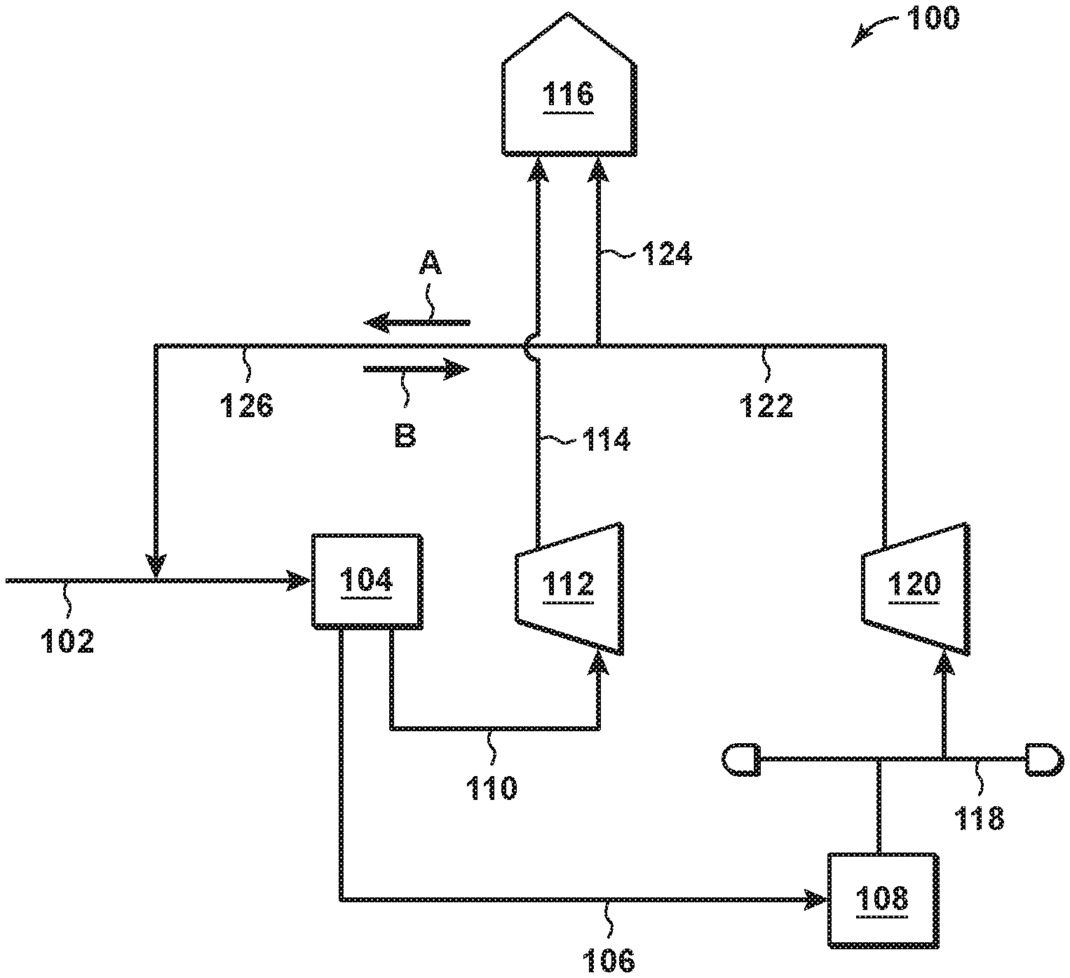
[0014] FIG. 1 is an illustrative diagram of a portion in a natural gas liquefaction plant.
[0015] FIG. 2 is an illustrative flow diagram of the subsystems of an example natural gas liquefaction plant.
DETAILED DESCRIPTION
[0016] This disclosure relates generally to the subsystem for and methods related to recycling liquefied natural gas (LNG) boil-off gas (BOG) in natural gas liquefaction plants. More specifically, the present disclosure utilized a bi-directional line to allow LNG BOG to be directed for liquefaction in a recycle mode or be directed for fuel gas in a fuel mode.
[0017] FIG. 1 is an illustrative diagram of a portion 100 of a natural gas liquefaction plant. The portion 100 includes a feed gas line 102 fluidly connected to a liquefaction subsystem 104 to supply feed gas to the liquefaction subsystem 104. The feed gas is natural gas having undergone the necessary treatments to be suitable for liquefaction. The treatments depend on the composition of the natural gas (e.g., sulfur, water, and mercury content) and can include, but are not limited to, condensate removal, acid gas removal, dehydration, mercury removal, heavy-hydrocarbon removal, and combinations thereof.
[0018] As used herein, when describing a line that fluidly connects two components, the line is used as a general term to encompass the line or lines that fluidly connect the two components and the other hardware like pumps, connectors, heat exchangers, and valves that may be installed along the line.
[0019] Referring again to FIG. 1, the liquefaction subsystem 104 liquefies the natural gas to produce LNG at substantially ambient pressure. As used herein, "substantially ambient pressure" refers to ambient pressure.+-.5 bar gauge (barG). Liquefaction subsystems are known in the art and can have several different configurations. Typically, liquefaction subsystems include one or more heat exchangers, an expansion valve or hydraulic turbine, one or more pumps, and a separator. Examples of liquefaction subsystems include, but are not limited to, those described in U.S. Pat. Nos. 5,916,260 and 6,658,892, U. S. Patent Application No. 2007/0193303 and PCT International Application No. WO2011/109117, each of which is incorporated herein by reference.
[0020] Generally, the feed gas can be at about 55 barg (about 798 psi gauge (psig)) to about 70 barg (about 1,015 psig) as introduced to the liquefaction subsystem 104. To reduce the pressure of feed gas in the liquefaction subsystem 104, the feed gas is typically passed from a cryogenic heat exchanger system across an expansion valve or hydraulic turbine (i.e. "flashed") before it is passed into a separator (i.e., the flash tank). As the pressure of the cooled feed gas is reduced to produce LNG at substantially ambient pressure, some of the gas flashes and becomes vapor known as end-flash gas (EFG). LNG is removed from the flash tank and is pumped from the liquefaction subsystem 104 on to an LNG storage tank 108 via an LNG line 106 that fluidly couples the liquefaction subsystem 104 and the LNG storage tank 108. The EFG is removed from the flash tank in the liquefaction subsystem 104 and pumped to an EFG compressor 112 via an EFG line 110 that fluidly couples the liquefaction subsystem 104 and the EFG compressor 112.
[0021] The EFG compressor 112 compresses the EFG to produce compressed EFG at a pressure of about 55 barg (about 798 psig) to about 70 barg (about 1,015 psig). The compressed EFG is supplied to a fuel gas subsystem 116 via compressed EFG line 114 that fluidly couples the EFG compressor 112 and the fuel gas subsystem 116. The fuel gas subsystem 116 provides fuel gas to various components of the natural gas liquefaction plant.
[0022] As described above, LNG in the LNG storage tank 108 vaporizes to LNG BOG over time due at least in part to heat from the surrounding environment warming the LNG. The LNG BOG is captured in an LNG BOG header 118 that fluidly couples the LNG storage tank 108 to an LNG BOG compressor 120. The LNG BOG compressor 120 compresses the LNG BOG to produce compressed LNG BOG at a pressure of about 55 barg (about 798 psig) to about 70 barg (about 1,015 psig). A compressed LNG BOG line 122 fluidly couples the LNG BOG compressor 120 to a fuel gas line 124 and a bidirectional line 126.
[0023] Compressed LNG BOG is supplied to the fuel gas line 124 in an amount needed to supply or augment the supply of fuel gas needed to run the natural gas liquefaction plant. This can be all of the compressed LNG BOG, some of the compressed LNG BOG, or none of the compressed LNG BOG. When there is excess compressed LNG BOG not needed for fuel gas, the excess compressed LNG BOG is conveyed to the feed gas line 102 via the bidirectional line 126 in the flow direction of arrow A. The excess compressed LNG BOG is entrained with the feed gas for liquefaction. This configuration in flow direction A is referred to herein as being in "recycle mode."
[0024] Alternatively, when all of the LNG BOG is insufficient to supply or augment the supply of fuel gas needed to run the natural gas liquefaction plant, at least a portion of the feed gas from feed gas line 102 can be conveyed to the fuel gas line 124 via the bidirectional line 126 in the flow direction of arrow B. This configuration in flow direction A is referred to herein as being in "fuel mode."
[0025] Accordingly, methods of the present disclosure can include supplying a feed gas to a liquefaction subsystem; liquefying the feed gas, which may be a natural gas, to produce LNG and EFG; compressing the EFG to compressed EFG; using the compressed EFG as fuel gas; storing the LNG in one or more LNG tanks; compressing LNG BOG from the one or more LNG tanks to produce compressed LNG BOG; and either (1) operating in a recycle mode by supplying at least a portion of the compressed LNG BOG to the feed gas via a bidirectional line, or (2) operating in a fuel mode by (a) supplying a portion of the feed gas to the fuel gas via the bidirectional line and (b) supplying the compressed LNG BOG to the fuel gas. In some instances, operating in recycle mode can further include supplying at least a portion of the compressed LNG BOG to the fuel gas.
[0026] Fuel demand at a natural gas liquefaction plant varies depending on the processes running. For example, typically several liquefaction subsystems 104 are operating in parallel. When some are off-line for maintenance or because supply or demand is low, the compressed EFG may be sufficient to supply the fuel gas needs of the plant. In such instances a portion of or none of the compressed LNG BOG may be needed to augment the supply of compressed EFG. In such instances, the portion 100 may operate in recycle mode.
[0027] In another example, the natural gas liquefaction plant may be operating several liquefaction subsystems 104 in parallel such that the combined amount of the compressed EFG and the compressed LNG BOG are insufficient to provide the amount fuel gas needed to operate the plant. In such instances, the portion 100 may operate in fuel mode.
[0028] In yet another example, the natural gas supply may have a low concentration of nitrogen, which results in lower amounts of EFG. Consequently, the portion 100 may operate in fuel mode more often than if the natural gas supply had a moderate to high concentration of nitrogen.
[0029] In the portion 100, the feed gas, the compressed LNG BOG, and the compressed EFG can each individually be at a pressure of about 55 barg (about 798 psig) to about 75 barg (about 1,088 psig), or about 58 barg (about 841 psig) to about 72 barg (about 1,044 psig), or about 60 barg (about 870 psig) to about 70 barg (about 1,015 psig), or about 62 barg (about 899 psig) to about 68 barg (about 986 psig).
[0030] FIG. 2 is an illustrative flow diagram of the subsystems 230 of an example natural gas liquefaction plant. In alternate embodiments, some of the subsystems 230 can be eliminated or bypassed, the subsystems 230 can be reordered, and/or additional subsystems 230 can be included.
[0031] In the illustrated subsystems 230, a natural gas supply 232 is provided to a gas receiving subsystem 234 and transported to a condensate removal subsystem 236. The condensate removal subsystem 236 extracts unstabilized condensate 238, which is transported to a condensate stabilization subsystem 240. The product from the condensate removal subsystem 236 is then treated through an acid gas removal subsystem 242, a dehydration subsystem 244, a mercury removal subsystem 246, and a precooling subsystem 248 before removal of heavy hydrocarbons 252 in the heavy-hydrocarbon removal subsystem 250. The heavy hydrocarbons 252 can be fractionated in a fractionation subsystem 254 into stabilized condensate 256, natural gas liquids 258 (NGL) (e.g., ethane, propane, butanes, and heavier hydrocarbons), and methane 260. The stabilized condensate 256 can be transported to a condensate storage subsystem 262, which is where the stabilized condensate 264 from the condensate stabilization subsystem 240 is also stored. The NGL 258 can be transported to a NGL storage subsystem 266. The methane 260 can be transported to a refrigeration subsystem 268 the cooled methane can be combined with the feed gas 270 product of the heavy-hydrocarbon removal subsystem 250.
[0032] Then, as described in FIG. 1, the feed gas 270 is provided to the liquefaction subsystem 272. The EFG 274 is compressed and transported to a fuel gas subsystem 276. The LNG 278 produced in the liquefaction subsystem 272 can be stored in an LNG storage subsystem 280. The LNG BOG 282 from the LNG storage subsystem 280 can be compressed.
[0033] Then, in recycle mode, at least a portion of the LNG BOG 282 can be transported via a bidirectional line 284 to be entrained with feed gas 270. Alternatively, in fuel mode, the LNG BOG 282 can be transported to the fuel gas subsystem 276 along with a portion of the feed gas 270 via the bidirectional line 284 according to flow arrows B.
[0034] Finally, as needed, the LNG in the LNG storage subsystem 280 can be transferred to transportation vessels 286 (e.g., tanker trucks, tanker railcars, and ships).
[0035] Methods of the present disclosure can include treating a natural gas supply by one or more methods to produce the feed gas for liquefaction, the one or more methods being selected from the group consisting of: condensate removal, acid gas removal, dehydration, mercury removal, precooling, heavy-hydrocarbon removal, and combinations thereof.
[0036] Unless otherwise indicated, all numbers expressing quantities of ingredients, properties such as molecular weight, reaction conditions, and so forth used in the present specification and associated claims are to be understood as being modified in all instances by the term "about." Accordingly, unless indicated to the contrary, the numerical parameters set forth in the following specification and attached claims are approximations that may vary depending upon the desired properties sought to be obtained by the embodiments of the present invention. At the very least, and not as an attempt to limit the application of the doctrine of equivalents to the scope of the claim, each numerical parameter should at least be construed in light of the number of reported significant digits and by applying ordinary rounding techniques.
[0037] One or more illustrative embodiments incorporating the invention embodiments disclosed herein are presented herein. Not all features of a physical implementation are described or shown in this application for the sake of clarity. It is understood that in the development of a physical embodiment incorporating the embodiments of the present invention, numerous implementation-specific decisions must be made to achieve the developer's goals, such as compliance with system-related, business-related, government-related and other constraints, which vary by implementation and from time to time. While a developer's efforts might be time-consuming, such efforts would be, nevertheless, a routine undertaking for those of ordinary skill in the art and having benefit of this disclosure.
[0038] While compositions and methods are described herein in terms of "comprising" various components or steps, the compositions and methods can also "consist essentially of" or "consist of" the various components and steps.
[0039] Therefore, the present invention is well adapted to attain the ends and advantages mentioned as well as those that are inherent therein. The particular embodiments disclosed above are illustrative only, as the present invention may be modified and practiced in different but equivalent manners apparent to those skilled in the art having the benefit of the teachings herein. Furthermore, no limitations are intended to the details of construction or design herein shown, other than as described in the claims below. It is therefore evident that the particular illustrative embodiments disclosed above may be altered, combined, or modified and all such variations are considered within the scope and spirit of the present invention. The invention illustratively disclosed herein suitably may be practiced in the absence of any element that is not specifically disclosed herein and/or any optional element disclosed herein. While compositions and methods are described in terms of "comprising," "containing," or "including" various components or steps, the compositions and methods can also "consist essentially of" or "consist of" the various components and steps. All numbers and ranges disclosed above may vary by some amount. Whenever a numerical range with a lower limit and an upper limit is disclosed, any number and any included range falling within the range is specifically disclosed. In particular, every range of values (of the form, "from about a to about b," or, equivalently, "from approximately a to b," or, equivalently, "from approximately a-b") disclosed herein is to be understood to set forth every number and range encompassed within the broader range of values. Also, the terms in the claims have their plain, ordinary meaning unless otherwise explicitly and clearly defined by the patentee. Moreover, the indefinite articles "a" or "an," as used in the claims, are defined herein to mean one or more than one of the element that it introduces.
* * * * *
D00000
D00001
D00002
XML
uspto.report is an independent third-party trademark research tool that is not affiliated, endorsed, or sponsored by the United States Patent and Trademark Office (USPTO) or any other governmental organization. The information provided by uspto.report is based on publicly available data at the time of writing and is intended for informational purposes only.
While we strive to provide accurate and up-to-date information, we do not guarantee the accuracy, completeness, reliability, or suitability of the information displayed on this site. The use of this site is at your own risk. Any reliance you place on such information is therefore strictly at your own risk.
All official trademark data, including owner information, should be verified by visiting the official USPTO website at www.uspto.gov. This site is not intended to replace professional legal advice and should not be used as a substitute for consulting with a legal professional who is knowledgeable about trademark law.