Lng Production System Equipped With Recondenser
HIROSE; Kenji ; et al.
U.S. patent application number 16/485883 was filed with the patent office on 2020-02-20 for lng production system equipped with recondenser. The applicant listed for this patent is L'Air Liquide, Societe Anonyme pour l'Etude et l'Exploitation des Procedes Georges Claude. Invention is credited to Kenji HIROSE, Loic JOLY, Daisuke NAGATA, Shinji TOMITA.
| Application Number | 20200056837 16/485883 |
| Document ID | / |
| Family ID | 63249524 |
| Filed Date | 2020-02-20 |
| United States Patent Application | 20200056837 |
| Kind Code | A1 |
| HIROSE; Kenji ; et al. | February 20, 2020 |
LNG PRODUCTION SYSTEM EQUIPPED WITH RECONDENSER
Abstract
An LNG production system including a boil off gas recondenser that can recondense boil off gas without using a BOG compressor and without depending on an LNG liquefaction process is provided.
| Inventors: | HIROSE; Kenji; (Kobe, JP) ; JOLY; Loic; (Paris, FR) ; NAGATA; Daisuke; (Kobe, JP) ; TOMITA; Shinji; (Kobe, JP) | ||||||||||
| Applicant: |
|
||||||||||
|---|---|---|---|---|---|---|---|---|---|---|---|
| Family ID: | 63249524 | ||||||||||
| Appl. No.: | 16/485883 | ||||||||||
| Filed: | February 13, 2018 | ||||||||||
| PCT Filed: | February 13, 2018 | ||||||||||
| PCT NO: | PCT/EP2018/053562 | ||||||||||
| 371 Date: | August 14, 2019 |
| Current U.S. Class: | 1/1 |
| Current CPC Class: | F25J 2290/34 20130101; F25J 1/0245 20130101; F25J 1/0249 20130101; F25J 1/0272 20130101; F25J 2235/60 20130101; F25J 1/0025 20130101; F25J 1/0244 20130101; F25J 1/0262 20130101; F25J 1/0204 20130101; F25J 2205/90 20130101; F25J 1/0022 20130101; F25J 1/0258 20130101; F25J 1/0251 20130101; F25J 1/0261 20130101; F25J 2240/40 20130101; F25J 1/0254 20130101; F25J 1/0072 20130101; F25J 1/0212 20130101; F25J 1/0052 20130101; F25J 2210/04 20130101; F25J 1/0045 20130101; F25J 2210/42 20130101; F25J 1/0264 20130101 |
| International Class: | F25J 1/00 20060101 F25J001/00 |
Foreign Application Data
| Date | Code | Application Number |
|---|---|---|
| Feb 14, 2017 | JP | 2017-024938 |
| Feb 28, 2017 | JP | 2017-036432 |
Claims
1-12. (canceled)
13. An LNG production system, comprising: a liquefier that cools and liquefies natural gas by indirect heat exchange with a refrigerant that is fed from a first refrigerator; an LNG tank that stores liquid natural gas liquefied in the liquefier; a transfer line for transferring the liquid natural gas from the LNG tank to an LNG carrier; a recondenser that recondenses boil off gas that is generated by the liquid natural gas, the recondensing performed by indirect heat exchange with the refrigerant fed from a second refrigerator; and a return line that feeds the recondensed boil off gas to the LNG tank from the recondenser.
14. The LNG production system of claim 13, wherein the first refrigerator and the second refrigerator are the same.
15. The LNG production system of claim 13, wherein the first refrigerator and the second refrigerator are different.
16. The LNG production system of claim 13, wherein the recondenser switches to perform, alternately, a first recondensation in a recondenser that recondenses boil off gas that is generated by the liquid natural gas, the recondensing performed by indirect heat exchange with the refrigerant fed from a second refrigerator, and a second recondensation wherein the boil off gas is recondensed by indirect heat exchange with the refrigerant from the second refrigerator and refrigerant from a refrigerant buffer, thereby processing more boil off gas than the boil off gas at a time of the first recondensation processing.
17. The LNG production system of claim 13, wherein the recondenser is designed to recondense the boil off gas by a refrigerant under a pressure lower than an operating pressure of the LNG tank.
18. The LNG production system of claim 13, wherein the recondenser is internally provided with a heat exchanger in which the refrigerant is introduced, and the boil off gas is introduced into the heat exchanger, and is cooled by the refrigerant.
19. The LNG production system of claim 18, wherein an external capacity of the heat exchanger is smaller than an internal space capacity of the recondenser, and the heat exchanger is disposed in the internal space of the recondenser.
20. A recondenser within an LNG production system that liquefies natural gas to produce liquid natural gas, and recondenses boil off gas in an LNG tank in which the liquid natural gas that is liquefied is stored, by a refrigerant, the condenser comprising: a return line that directly feeds liquid natural gas that is recondensed to the LNG tank.
21. The recondenser of claim 20, wherein the recondenser is designed to recondense the boil off gas by a refrigerant under a pressure lower than an operating pressure of the LNG tank.
22. The recondenser of claim 20, wherein the recondenser is internally provided with a heat exchanger in which the refrigerant is introduced, and the boil off gas is introduced into the heat exchanger, and is cooled by the refrigerant.
23. The recondenser of claim 22, wherein an external capacity of the heat exchanger is smaller than an internal space capacity of the recondenser, and the heat exchanger is disposed in the internal space of the recondenser.
Description
TECHNICAL FIELD
[0001] The present invention relates to an LNG production system equipped with a recondenser (Recondenser) that recondenses (reliquefies) boil off gas (BOG, Boil off Gas).
BACKGROUND ART
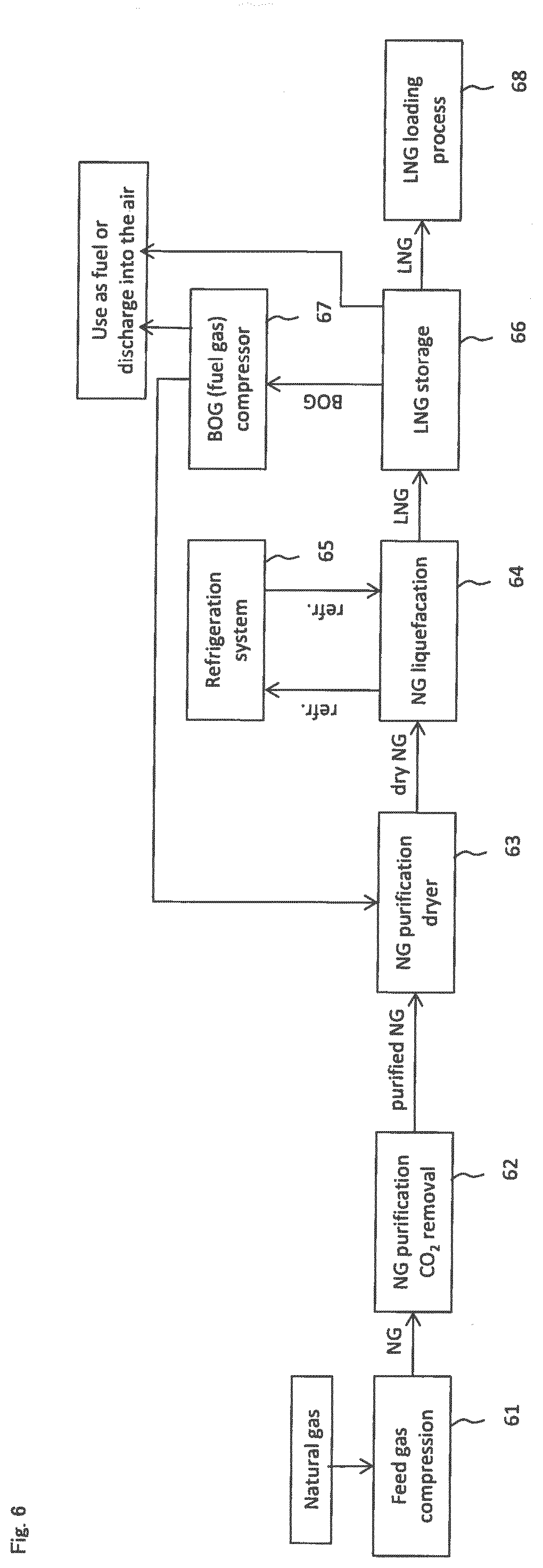
[0002] FIG. 6 illustrates a general LNG production system. Natural gas (NG, Natural Gas) is fed to a CO.sub.2 removal process 62 in a subsequent stage by a compressor 61. In the CO.sub.2 removal process 62, CO.sub.2 is removed from the natural gas by using a predetermined solvent. The NG after removal from which CO.sub.2 is removed is fed to a dry process 63. In the dry process 63, predetermined drying treatment is applied to the NG after removal. The dried NG is fed to a liquefaction process 64. In the liquefaction process 64, the dried NG is liquefied by using a liquid refrigerant that is fed from a refrigeration system 65. The liquid natural gas (LNG) obtained by liquefaction is fed to an LNG storage tank 66. Subsequently, in an LNG loading process 68, LNG is fed from the LNG storage tank 66 at a predetermined timing (for example, at the timing at which the LNG is transferred to a transport ship tank, or the like). Here, LNG in the LNG storage tank 66 sometimes evaporates by natural heat input and generates BOG. Further, when LNG is transferred to the transport ship tank from the LNG storage tank 66 in the LNG loading process 68, a large amount of BOG is sometimes generated. Further, piping is cooled when LNG is transferred to the transport ship tank, so that BOG is sometimes generated.
[0003] Many LNG storage tanks 66 which are installed in the LNG production bases have large capacities, and design pressure thereof is generally set at a vicinity of the atmospheric pressure from the viewpoints of technology and cost. Consequently, it is necessary to discharge BOG from the LNG storage tank 66 even at the time of a slight pressure increase. Further, the pressure increase also occurs by a piston effect (also referred to as "pushup effect") accompanying supply of LNG to the LNG storage tank 66 from the liquefaction process 64, and therefore supply of LNG to the LNG storage tank 66 causes regular discharge of BOG. Further, a flash loss of decompression accompanying charge to the LNG storage tank 66 from a liquefier of the liquefaction process 64 also occurs. Note that LNG loss by a flash loss sometimes occupies approximately 50% of the BOG generation amount.
[0004] However, it is undesirable to discharge BOG into the atmosphere in terms of environmental and economical aspects, so that BOG is conventionally returned to the dry process 63 by a compressor 67, and is supplied to the liquefaction process 64 with the dried NG. Thereby, it is possible to reliquefy BOG. Alternatively, BOG is sometimes used as the heat source for regeneration of a drying material or the like in the dry process 63.
[0005] However, in the case of reliquefaction of the BOG described above, a total amount of NG that is fed to the liquefaction process 64 from the dry process 63 includes the recycled BOG. Further, use as the fuel gas means that the total amount of LNG which is produced cannot be transferred to the transport ship tank.
[0006] Further, it is required to bring BOG into a high pressure state in order to reliquefy the BOG, so that the compressor 67 is required at the time of recycle that returns the BOG to the dry process 63. Consequently, consumption of a large amount of energy is required to compress the BOG.
[0007] Further, when BOG is returned to the dry process 63 as described above, BOG can be reliquefied only at the lime of LNG production, so that when BOG has to be discharged from the LNG storage tank at the time of producing no LNG, BOG has to be discharged into the air. That is, the timing for reliquefaction is limited, and there is no flexibility in reliquefaction process.
[0008] The LNG production system described in Patent Literature 1 presents no method of solution to the above described problem.
CITATION LIST
Patent Literature
[0009] [Patent Literature 1] U. S. Patent No. 2011/0094261
SUMMARY OF INVENTION
Technical Problem
[0010] An object of the present invention is to provide an LNG production system including a recondenser that can recondense BOG (boil off gas) without using a BOG compressor and without depending on an LNG liquefaction process.
Solution to Problem
[0011] A first LNG production system of the present invention includes
[0012] a liquefier that cools and liquefies natural gas by a refrigerant that is fed from a refrigerator,
[0013] an LNG tank that stores liquid natural gas (LNG) liquefied in the liquefier,
[0014] a transfer line for transferring the liquid natural gas from the LNG tank,
[0015] an LNG carrier that is disposed in a subsequent stage of the transfer line and is for transferring the liquid natural gas,
[0016] a recondenser that recondenses (reliquefies) boil off gas that is generated by heat being given to the liquid natural gas, by the refrigerant fed from the refrigerator, and
[0017] a return line that feeds liquid natural gas that is liquefied to the LNG tank from the recondenser.
[0018] A second LNG production system of the present invention includes
[0019] a liquefier that cools and liquefies natural gas by a refrigerant that is fed from a first refrigerator,
[0020] an LNG tank that stores liquid natural gas liquefied in the liquefier,
[0021] a transfer line for transferring the liquid natural gas from the LNG tank,
[0022] an LNG carrier that is disposed in a subsequent stage of the transfer line and is for transferring the liquid natural gas,
[0023] a recondenser that recondenses boil off gas (BOG) that is generated by heat being given to the liquid natural gas, by a refrigerant fed from the second refrigerator, and
[0024] a return line that feeds liquid natural gas that is liquefied to the LNG tank from the recondenser.
[0025] In the above described invention, the refrigerant that is fed from the first refrigerator, and the refrigerant that is fed from the second refrigerator may be the same refrigerants, or may be different refrigerants. For example, as the refrigerant from the first refrigerator, a mixture such as hydrocarbon is cited, and as the refrigerant from the second refrigerator, nitrogen or the like is cited.
[0026] A third LNG production system of the present invention includes
[0027] a liquefier that cools and liquefies natural gas by a refrigerant that is fed from a refrigerator,
[0028] an LNG tank that stores liquid natural gas liquefied in the liquefier,
[0029] a transfer line for transferring the liquid natural gas from the LNG tank,
[0030] an LNG carrier that is disposed in a subsequent stage of the transfer line and is for transferring the liquid natural gas,
[0031] a recondenser that switches to perform, alternately, a first recondensation processing of liquefying boil off gas that is generated by heat being given to the liquid natural gas, by the refrigerant fed from the refrigerator, and a second recondensation processing of liquefying boil off gas by the refrigerant fed from the refrigerator and a refrigerant fed from a refrigerant buffer to process more boil off gas than the boil off gas at a time of the first recondensation processing, and
[0032] a return line that feeds liquid natural gas that is liquefied to the LNG tank from the recondenser.
[0033] In the above described invention, the refrigerant that is fed from the refrigerator, and the refrigerant that is fed from the refrigerant buffer may be the same refrigerants, or may be different refrigerants. For example, as the refrigerant from the refrigerator, a mixture such as hydrocarbon is cited, and as the refrigerant from the refrigerant buffer, nitrogen or the like is cited.
[0034] In the aforementioned first recondensation processing, the refrigerant may be fed to the recondenser from the refrigerator, and in the second recondensation processing, the refrigerant from the refrigerant buffer may be fed to the recondenser in addition to that the refrigerant is fed to the recondenser from the refrigerator. In the case of switching to the second recondensation processing from the first recondensation processing, the operation of the refrigerator may be stopped, or the refrigerator may be continuously operated without stopping.
[0035] The recondenser may have a switch control section that switches the first recondensation processing and the second recondensation processing to each other.
[0036] The switch control section may switch from the first recondensation processing to the second recondensation processing, in the case of transferring BOG to the LNG carrier.
[0037] The switch control section may switch from the first recondensation processing to the second recondensation processing when a pressure value measured by a pressure gauge disposed in the LNG tank or the feed line that feeds the BOG to the recondenser becomes a predetermined value or more.
[0038] According to the above described respective configurations, in the case of processing BOG in an amount in a predetermined range (a flow rate per unit time) or of a pressure value in a predetermined range that is set in advance, the first recondensation processing (processing of liquefying BOG with the refrigerant from the refrigerator) is executed, and in the case of processing BOG that exceeds the above described amount in the predetermined range or pressure value in the predetermined range, the second recondensation processing (processing of liquefaction also by the refrigerant fed from the refrigerant buffer while keeping liquefaction by the refrigerant fed from the refrigerator) can be executed, so that BOG can be recondensed without using a BOG compressor and without depending on the LNG liquefaction process.
[0039] In each of the above described first to third LNG production system, predetermined treatment may be applied to the aforementioned natural gas that is fed to the liquefier in advance. For example, each of the LNG production systems may include a removing device that removes predetermined impurities from natural gas, and a dryer that dries the natural gas that is treated by the removing device.
[0040] The transfer line may be provided with piping and a sluice valve.
[0041] The return line may be provided with piping, a pump for feeding LNG and an automatic on-off valve.
[0042] A feed line that feeds the BOG to the recondenser from the LNG tank may be included. The feed line may be provided with any one or more of piping, an automatic on-off valve, a flow rate control valve and a pressure regulating valve.
[0043] A pressure gauge that measures the pressure of the LNG tank may be provided. When a pressure value of the pressure gauge reaches a predetermined value or more, valves of the feed line and the return line may open, and BOG may be fed to the recondenser through the feed line.
[0044] The recondenser may be controlled so as to increase a cooling capability of the recondenser when the pressure value of the pressure gauge installed in the feed line reaches the predetermined value or more. For example, control may be performed so as to increase the feeding amount of the refrigerant that is fed from the refrigerator (the first or the second refrigerator), for example.
[0045] The LNG carrier may be, for example, a loading station container, a loading pier, a loading station truck, and the like.
[0046] A recovery line for returning BOG that is present in the LNG carrier to the LNG tank may be provided.
[0047] In the third LNG production system, the refrigerant stored in the refrigerant buffer may be supplied from the refrigerator or an external refrigerator.
[0048] The recondenser may have a piping through which the refrigerant fed from the refrigerator passes, and a piping through which the refrigerant fed from the refrigerant buffer passes as separate components, and the returning refrigerants may be returned together to the refrigerator.
[0049] The recondenser may have a first heat exchanger to which the refrigerant fed from the refrigerator is introduced, and a second heat exchanger to which the refrigerant fed from the refrigerant buffer is introduced.
[0050] In each of the above described first to third LNG production systems, the recondenser preferably has the following configuration.
[0051] The recondenser is designed to recondense (liquefy) the boil off gas by a refrigerant under a pressure lower than an operating pressure of the LNG tank.
[0052] According to the configuration, BOG can be recondensed under the pressure lower than the operating pressure of the LNG tank without using the conventional BOG compressor.
[0053] The recondenser may be internally provided with a heat exchanger into which the refrigerant is introduced, and the BOG may be introduced into the heat exchanger, and is cooled by the refrigerant. Thereby, BOG can be effectively liquefied in a mode of the heat exchanger.
[0054] A volume (an external capacity) of the heat exchanger may be smaller than an internal volume (an internal space capacity) of the recondenser, and the heat exchanger may be disposed in the internal space of the recondenser.
[0055] Thereby, BOG can be effectively liquefied in the mode of the heat exchanger. The liquefied LNG accumulates on the bottom of the recondenser. The accumulating LNG can be fed to the LNG tank by a liquid feed pump.
[0056] The pressure in the recondenser or in the heat exchanger may be regulated as follows.
(1) Before sending BOG, feed the refrigerant, and pre-cool the inside of the recondenser or the inside of the heat exchanger. After a lapse of a predetermined time period, or when the inside of the recondenser or the inside of the heat exchanger reaches a predetermined temperature, start introduction of BOG. (2) The introduced BOG is liquefied, and accumulates on the bottom of the recondenser or the heat exchanger. The liquefied LNG accumulating on the bottom can be fed to the LNG tank by the pump, a pressurizing device or the like.
[0057] A fourth LNG production system of the present invention includes
[0058] a liquefier that cools and liquefies natural gas by a refrigerant that is fed from a refrigerator,
[0059] an LNG tank that stores liquid natural gas liquefied in the liquefier,
[0060] a transfer line for transferring the liquid natural gas from the LNG tank,
[0061] an LNG carrier that is disposed in a subsequent stage of the transfer line and is for transferring the liquid natural gas,
[0062] an LNG lead-out line that leads out the liquid natural gas from the LNG tank,
[0063] a sub-cooler that is provided in the LNG lead-out line and cools the liquid natural gas with a refrigerant (for example, liquid nitrogen or the like),
[0064] a recondenser that recondenses boil off gas that is generated by heat being given to the liquid natural gas, by the liquid natural gas cooled in the sub-cooler, and
[0065] a return line that feeds liquid natural gas that is liquefied to the LNG tank from the recondenser.
[0066] In the present invention, the recondenser may recondense (liquefy) boil off gas with LNG that is cooled by the sub-cooler under a pressure lower than an operating pressure of the LNG tank.
[0067] According to the configuration, the liquid natural gas is firstly cooled by using the refrigerant such as LN.sub.2, and boil off gas is liquefied with the cooled liquid natural gas. Thereby, recondensation of boil off gas can be effectively performed under the pressure lower than the operating pressure of the LNG tank.
[0068] In the fourth invention, the sub-cooler may be controlled so that liquid natural gas has a higher temperature than a solidifying point of the liquid natural gas by the pressure regulating valve or the flow rate regulating valve that is installed in the refrigerant line in which the refrigerant flows.
[0069] In the fourth invention, two or more of the sub-coolers may be adopted. In the case of the two sub-coolers, the first recondensation processing of liquefying BOG by the refrigerant fed from the first sub-cooler, and the second recondensation processing of liquefying BOG by the refrigerant fed from the first sub-cooler and the refrigerant fed from the second sub-cooler in order to process more boil off gas than the boil off gas at a time of the first recondensation processing may be performed by switching the first recondensation processing and the second recondensation processing to each other. In the case of switching from the first recondensation processing to the second recondensation processing, the operation of the refrigerator may be stopped, or the refrigerator may be continuously operated without stopping.
[0070] The recondenser may have a switch control section that switches the first recondensation processing and the second recondensation processing to each other.
[0071] The switch control section may switch from the first recondensation processing to the second recondensation processing in the case of transferring boil off gas to the LNG carrier.
[0072] The switch control section may switch from the first recondensation processing to the second recondensation processing when a pressure value measured by a pressure gauge disposed in the LNG tank or the feed line that feeds the BOG to the recondenser becomes a predetermined value or more.
[0073] The refrigerant in the second sub-cooler may be supplied from the refrigerant buffer in which the refrigerant is stored in advance.
[0074] In the above described LNG production system, the pump for feeding liquid natural gas (LNG) to the transfer line from the LNG tank may be an in-tank type pump that is installed inside the LNG tank, or may be a pump that is disposed on the transfer line.
BRIEF DESCRIPTION OF DRAWINGS
[0075] FIG. 1 is a diagram illustrating a configuration example of an LNG production system of embodiment 1.
[0076] FIG. 2 is a diagram illustrating a configuration example of an LNG production system of embodiment 2.
[0077] FIG. 3 is a diagram illustrating a configuration example of an LNG production system of embodiment 3.
[0078] FIG. 4A is a diagram illustrating a configuration example of a recondenser.
[0079] FIG. 4B is a diagram illustrating a configuration example of the recondenser.
[0080] FIG. 4C is a diagram illustrating a configuration example of the recondenser.
[0081] FIG. 5A is a diagram illustrating a configuration example of an LNG production system in embodiment 4.
[0082] FIG. 5B is a diagram illustrating a configuration example of the recondenser.
[0083] FIG. 5C is a diagram illustrating a configuration example of the recondenser.
[0084] FIG. 6 is a diagram illustrating a configuration example of a conventional LNG production system.
DESCRIPTION OF EMBODIMENTS
[0085] Hereunder, several embodiments of the present invention will be described. The embodiments described as follows explain only examples of the present invention. The present invention is not limited by the following embodiments in any way, and also includes various modified modes that are carried out within the range without changing the gist of the present invention. Note that all of components described as follows are not always indispensable components of the present invention.
Embodiment 1
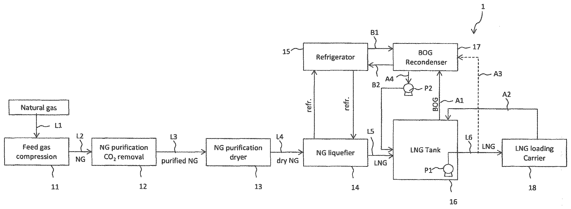
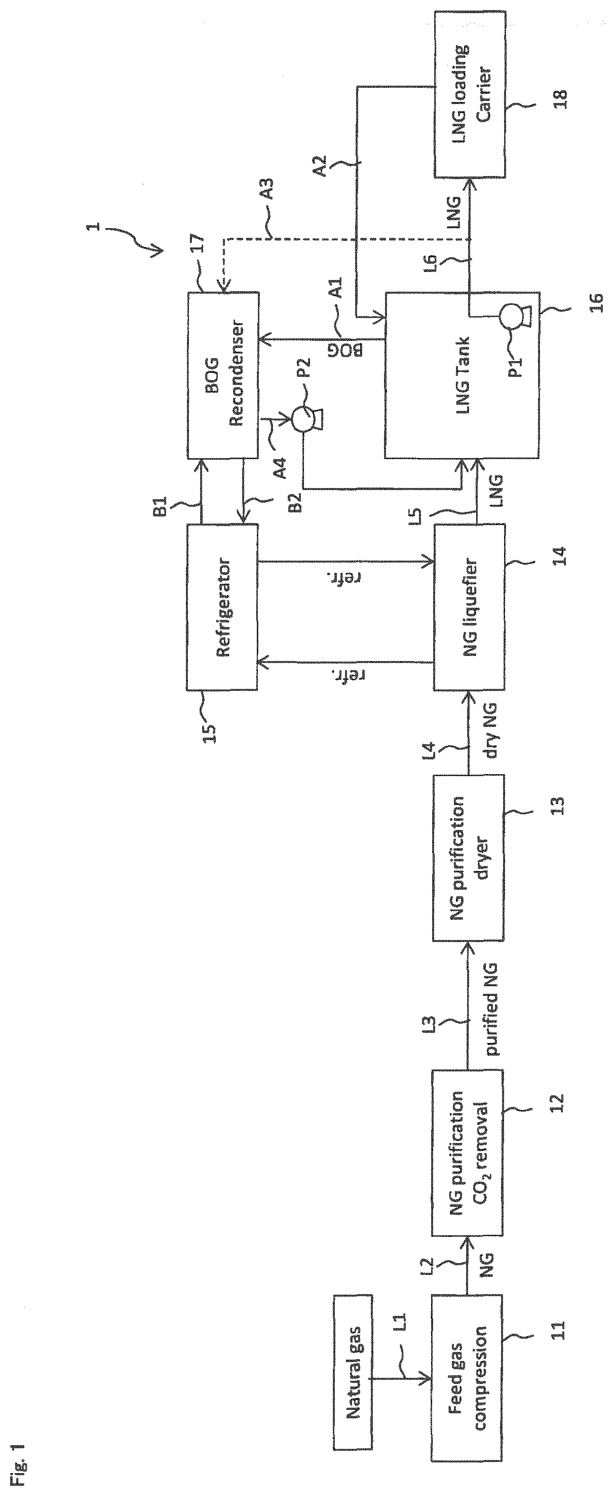
[0086] An LNG production system 1 of embodiment 1 will be described with reference to FIG. 1. The LNG production system 1 has a first line L1 for transferring natural gas to a process in a subsequent stage, a compressor 11 and a second line L2 (a pipe, for example). As the process in the subsequent stage, a removing unit 12 is disposed, and a predetermined substance (CO2, for example) is removed from NG here. Next, the NG after removal is fed to a dryer 13 through a third line L3, and is subjected to drying treatment. Next, the dried NG is fed to a liquefier 14 through a fourth line L4 and is liquefied. A refrigerant (a liquid refrigerant) is fed to the liquefier 14 from a refrigerator 15 to cool NG, and LNG is obtained. Further, the refrigerant which is subjected to heat exchange returns to the refrigerator 15 in an evaporated state. LNG is fed to the LNG tank 16 through a fifth line L5 and stored. The first line L1 to the fifth line L5 are configured by pipes and on-off valves, for example. A predetermined control device (controller) controls operation of the respective devices, opening and closing of the valves, a production amount of LNG, and the like of the LNG production system 1.
[0087] In the LNG tank 16, an in-tank type first pump P1 is disposed, and LNG in the tank is fed into an LNG carrier 18 through a transfer line L6 by the first pump P1. As the LNG carrier 18, for example, a loading station container, a loading pier, a loading station track, and the like are cited. BOG that is present in the LNG carrier 18 is fed to the LNG tank 16 through a recovery line A2. Instead of or in addition to the recovery line A2, a second feed line for feeding BOG present in the LNG carrier 18 to a recondenser 17 may be provided.
[0088] In the LNG tank 16, BOG is generated by heat input. Further, when LNG is fed from the liquefier 14, BOG is also generated. Further, when LNG is fed to the LNG carrier 18, BOG is also generated. In this way, BOG in the LNG tank 16 is fed to the recondenser 17 through a first feed line A1. Further, BOG in the transfer line L6 is fed to the recondenser 17 through a third feed line A3.
[0089] A refrigerant (liquid refrigerant) is introduced into the recondenser 17 through a refrigerant line B1 from the refrigerator 15. By the refrigerant, BOG fed by each of the feed lines is recondensed (liquefied). A configuration of the recondenser 17 is described later. The LNG that is obtained by being recondensed (liquefied) is returned to the LNG tank 16 through a return line A4. In the return line A4, a second pump P2 is disposed, and LNG is fed to the LNG tank 16 by operating the second pump P2.
[0090] According to the present embodiment, a series of processes is not required, which feeds BOG to the dryer and feeds BOG to the liquefier with NG to liquefy BOG as in the conventional art. Consequently, it is not necessary to operate the entire LNG production system, and only the refrigerator 15 can be operated. The recondenser 17 can recondense BOG to LNG, so that all of the liquefaction capability of the liquefier 14 can be used in liquefaction of NG that is fed from the dryer.
(Recondenser)
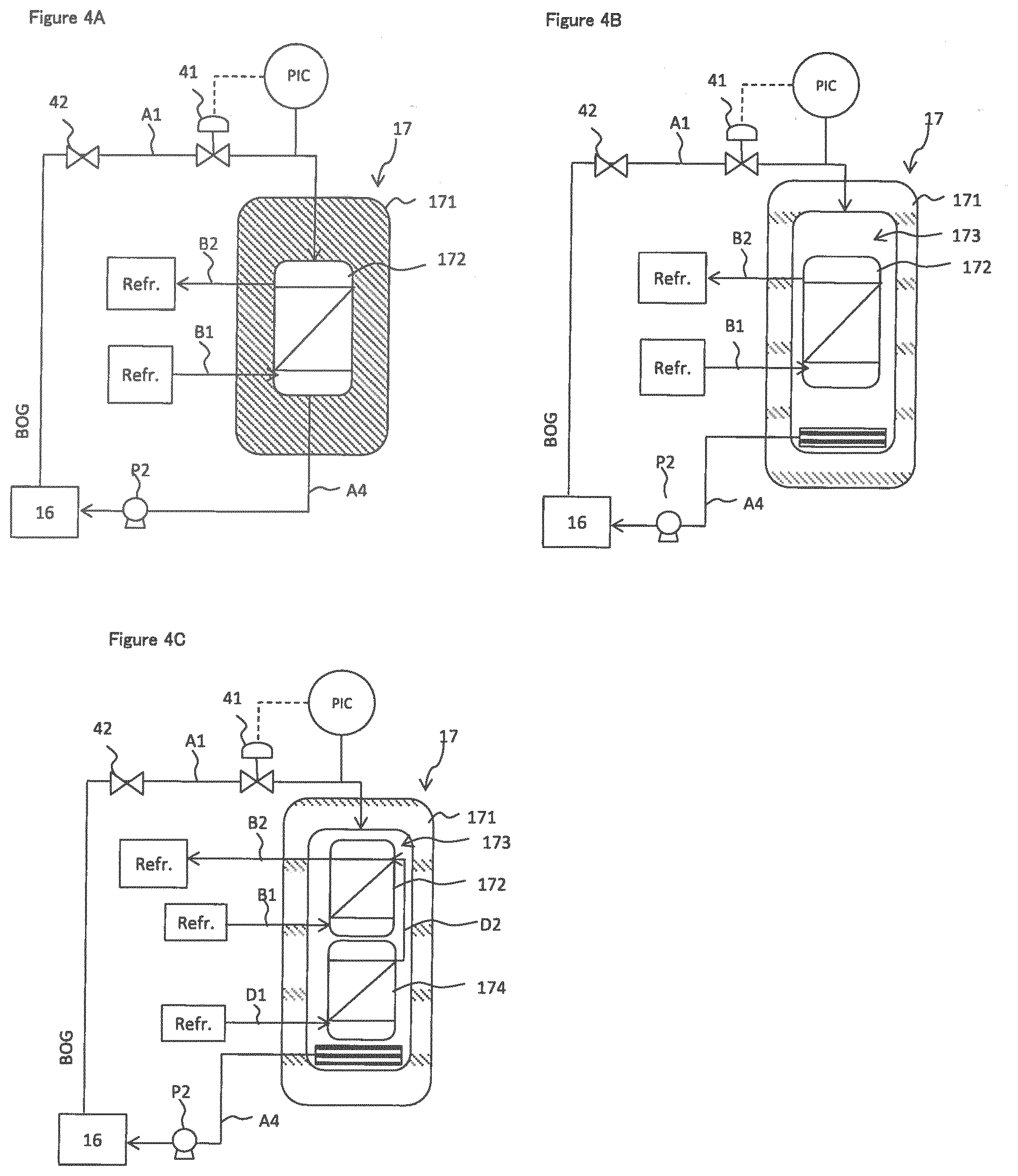
[0091] FIGS. 4A and 4B illustrate an embodiment of the recondenser 17. In FIG. 4A, the recondenser 17 has an outer wall 171, and a heat exchanger 172 covered with the outer wall 171. A refrigerant (a liquid refrigerant) is introduced into the heat exchanger 172 from the refrigerator 15 through a refrigerant line B1, and BOG is cooled by cold energy of the refrigerant. The refrigerant evaporates and returns to the refrigerator 15 through a refrigerant return line B2. LNG is fed to the LNG tank 16 from the recondenser 17 by the second pump P2.
[0092] The recondenser 17 is designed to recondense (liquefy) BOG with the refrigerant under a pressure lower than an operating pressure of the LNG tank 16.
[0093] The first feed line A1 may be provided with a safety valve for a time when the pressure in the LNG tank 16 becomes abnormally high. Further, in the first feed line A1, an automatic on-off valve 42 for performing feeding control of BOG to the recondenser 17 is provided. Further, in the first feed line A1, a pressure gauge, and a pressure regulating valve 41 controlled in accordance with a value of the pressure gauge are provided.
[0094] The operating pressure in the LNG tank 16 is an average of 1.2 barA (120 KPaA) in absolute pressure, and is controlled within .+-.15% as upper and lower limit values. When a large amount of BOG is generated, a tank internal pressure becomes high. The tank internal pressure is measured with a pressure gauge, and based on a measurement result (a conversion result), a valve control section (not illustrated) controls opening and closing of the automatic on-off valve 42. For example, when the tank internal pressure becomes 1.3 times as high as 1.2 barA (120 KPaA), BOG is fed to the recondenser 17. As for the pressure regulating valve 41, in-pipe pressure of the first feed line A1 is measured, and a valve opening degree is controlled based on the measurement result.
[0095] The refrigerant which is supplied from the refrigerator 15 may be any medium having a lower temperature than a boiling point of LNG, and LN2 may be used, for example.
[0096] Internal pressure of the heat exchanger 172 is controlled to be a pressure lower than the operating pressure (average of 1.2 barA (120 KPaA) in absolute pressure) of the LNG tank 16, in a BOG recondensation processing. The internal pressure of the heat exchanger 172 is measured with a pressure gauge, and is regulated to be lower than the operating pressure of the LNG tank 16. In the present embodiment, the refrigerant contacts BOG in the heat exchanger 172, whereby a volume of BOG decreases by liquefaction and the pressure in the heat exchanger 172 is reduced. During operation, the low pressure state is kept by the refrigerant being continuously supplied. The internal pressure of the heat exchanger 172 is regulated by controlling a flow rate of the refrigerant. A flow rate regulating valve (not illustrated) is provided in the refrigerant feed line B1, and the flow rate of the refrigerant may be controlled with the flow rate regulating valve in accordance with a measurement result of the pressure gauge that measures the internal pressure of the above described heat exchanger 172.
[0097] Note that the recondenser 17 is not limited to a mode of the heat exchanger 172, but may be a mode in which BOG and the refrigerant are brought into direct contact with each other. As a method for contacting both BOG and the refrigerant to each other, means of spraying the refrigerant by a shower, means of contacting both of them by using a filler and the like are cited. A lower portion of the heat exchanger 172 and the return line A4 are connected. An automatic on-off valve (not illustrated) provided in the return line A4 is controlled to open and close, and the second pump P2 is controlled, whereby LNG can be fed back to the LNG tank 16 from the recondenser 17. A processing procedure of recondensation processing of boil off gas (BOG) will be described hereunder.
(1) Feed the refrigerant to the heat exchanger 172 from the refrigerator 15, and pre-cool the heat exchanger 172, when the tank internal pressure of the LNG tank 16 exceeds a first threshold value. A temperature of the refrigerant is preferably set at a temperature higher than an LNG solidifying point, and lower than a temperature of LNG in the LNG tank 16, for example. The temperature of LNG which is cooled may be set based on an amount of BOG and an amount of LNG which is cooled. (2) When the heat exchanger 172 reaches a predetermined temperature or less, regulate the supply amount of the refrigerant by the flow rate regulating valve (not illustrated) provided in the refrigerant line B1 to keep the temperature. (3) When the tank internal pressure of the LNG tank 16 exceeds a second threshold value (the second threshold value>the first threshold value), open the automatic on-off valve 42 and the pressure regulating valve 41, and introduce BOG directly into the heat exchanger 172 of the recondenser 17 from the LNG tank 16. At the time of introducing the BOG, regulate the supply amount of the refrigerant to the heat exchanger 172, and keep the inside of the heat exchanger 172 under a negative pressure (or under a pressure lower than the operating pressure of the LNG tank 16). (4) The heat exchanger 172 is pre-cooled, and BOG is cooled immediately and changes state to LNG, and the LNG drops onto a bottom of the heat exchanger 172. (5) LNG is fed back to the LNG tank 16 through the return line A4. (6) Close the respective valves after the recondensation processing ends.
[0098] It is assumed that a condition of (3) (the tank internal pressure>the second threshold value) is established during processing of (1) and/or (2), so that BOG may be configured to be discharged from the LNG tank 16 with a safety valve (not illustrated), or BOG may be discharged to external air by a vent not illustrated.
[0099] The above described "first threshold value" is a pressure that is 1.26 times as high as 1.2 barA (120 KPaA), for example.
[0100] The above described "second threshold value" is a pressure that is 1.3 times as high as 1.2 barA (120 KPaA), for example.
[0101] A pressure regulating valve (not illustrated) or a flow rate regulating valve (not illustrated) may be installed in the refrigerant line B1, and a refrigerant feed amount (VN) and a BOG feed amount (VB) may be controlled to VN>VB.
Other Embodiments
[0102] A recondenser in FIG. 4B will be described. In FIG. 4B, in the recondenser 17, a volume (an external capacity) of the heat exchanger 172 is smaller than an internal volume (an internal space capacity) of the recondenser 17, and the heat exchanger 172 is disposed in an internal space 173 of the recondenser. In the mode of the heat exchanger, BOG can be effectively liquefied. The liquefied LNG accumulates on a bottom of the internal space 173 of the recondenser 17. The accumulating LNG can be fed to the LNG tank 16 by the second pump P2.
[0103] An upper portion (preferably an upper side of the heat exchanger 172) of the internal space 173 of the recondenser 17 and the first feed line A1 are directly connected. Further, a lower portion of the internal space 173 of the recondenser 17 and the return line A4 are directly connected.
[0104] An internal pressure of the recondenser 17 is controlled to be a pressure lower than the operating pressure (an average of 1.2 barA (120 KPaA) in absolute pressure) of the LNG tank 16 in the BOG recondensation processing. The internal pressure of the recondenser 17 is measured by a pressure gauge, and is regulated to be lower than the operating pressure of the LNG tank 16.
[0105] In the present embodiment, the refrigerant is fed to the heat exchanger 172, and thereby the inside of the recondenser 17 is cooled. When BOG is introduced into the cooled recondenser 17, the volume of BOG decreases by liquefaction and the pressure inside the recondenser 17 is reduced. During operation, the refrigerant is continuously supplied to the heat exchanger 172 and thereby continues to cool the inside of the recondenser 17 to liquefy BOG to keep the inside of the recondenser 17 in a low-pressure state. The internal pressure of the recondenser 17 is regulated by controlling the flow rate of the refrigerant. A flow rate regulating valve is provided in the refrigerant line B1, and the flow rate of the refrigerant may be controlled by the flow rate regulating valve in accordance with the measurement result of the pressure gauge that measures the internal pressure of the above described recondenser 17, the flow rate of the refrigerant may be controlled by controlling the opening degree of the automatic on-off valve provided in the refrigerant line B1, or both of them may be controlled.
[0106] A processing procedure of the recondensation processing of boil off gas (BOG) will be described hereunder.
(1) Feed the refrigerant to the heat exchanger 172, and pre-cool the heat recondenser 17, when the tank internal pressure of the LNG tank 16 exceeds a first threshold value. A temperature of the refrigerant is preferably set at a temperature higher than the LNG solidifying point, and lower than a temperature of LNG in the LNG tank 16, for example. The temperature of LNG which is cooled may be set based on an amount of BOG and an amount of LNG which is cooled. (2) When the recondenser 17 reaches a predetermined temperature or less, regulate the supply amount of the refrigerant by the flow rate regulating valve (not illustrated) provided in the refrigerant line B1 to keep the temperature. (3) When the tank internal pressure of the LNG tank 16 exceeds a second threshold value (the second threshold value>the first threshold value), open the automatic on-off valve 42 and the pressure regulating valve 41, and introduce BOG into the recondenser 17 from the LNG tank 16. At the time of introducing the BOG, regulate the supply amount of the refrigerant to the heat exchanger 172, and keep the inside of the heat exchanger 172 under a negative pressure (or under a pressure lower than the operating pressure of the LNG tank 16). (4) The recondenser 17 is pre-cooled, and BOG is cooled immediately and changes state to LNG, and the LNG accumulates on the bottom of the recondenser 17. (5) LNG that accumulates on the bottom of the recondenser 17 is fed back to the LNG tank 16 through the return line A4. (6) Close the respective valves after the recondensation processing ends.
[0107] It is assumed that a condition of (3) (the tank internal pressure>the second threshold value) is established during processing of (1) and/or (2), so that BOG may be configured to be discharged from the LNG tank 16 with a safety valve (not illustrated), or BOG may be discharged to external air by a vent not illustrated.
[0108] The above described "first threshold value" is a pressure that is 1.26 times as high as 1.2 barA (120 KPaA), for example.
[0109] The above described "second threshold value" is a pressure that is 1.3 times as high as 1.2 barA (120 KPaA), for example.
[0110] A pressure regulating valve (not illustrated) or a flow rate regulating valve (not illustrated) may be installed in the refrigerant line B1, and a refrigerant feed amount (VN) and a BOG feed amount (VB) may be controlled to VN>VB.
Embodiment 2
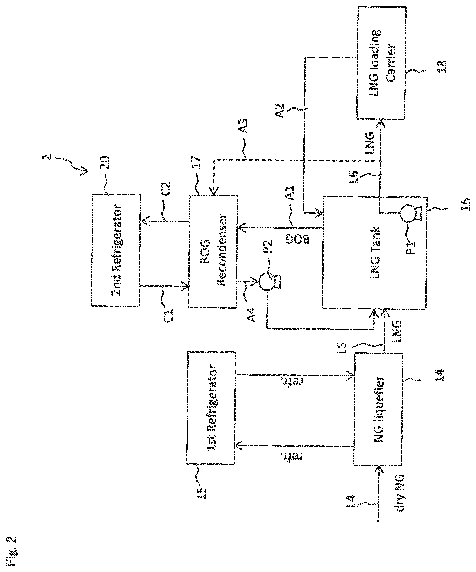
[0111] An LNG production system 2 of embodiment 2 will be described with use of FIG. 2. Components with the same reference signs as those in the LNG production system 1 of embodiment 1 have the same functions, and therefore, explanation of the components will be omitted, or will be made briefly.
[0112] The LNG production system 2 of embodiment 2 has the first refrigerator 15 and a second refrigerator 20. The first refrigerator feeds a refrigerant to a cooling device 14. The second refrigerator 20 feeds the refrigerant (liquid refrigerant) to the recondenser 17 through a refrigerant line C1 (corresponding to B1 in FIG. 1), and returns the refrigerant used as a cold source in the recondenser 17 through a return line C2 (corresponding to B2 in FIG. 1).
[0113] Consequently, since the second refrigerator 20 is provided separately from the first refrigerator 15, it is not necessary to supply the refrigerant to the operating cooling device 14 from the large refrigerator and supply the refrigerant to the recondenser 17, it is not necessary to install the refrigerator that is larger than necessary, and only a medium or small refrigerator can be installed, so that the installation space can be small, and the initial cost and the running cost can be reduced.
Embodiment 3
[0114] An LNG production system 3 of embodiment 3 will be described with reference to FIG. 3. Components with the same reference signs as those in the LNG production system 1 of embodiment 1 have the same functions, and therefore, explanation of the components will be omitted, or will be made briefly.
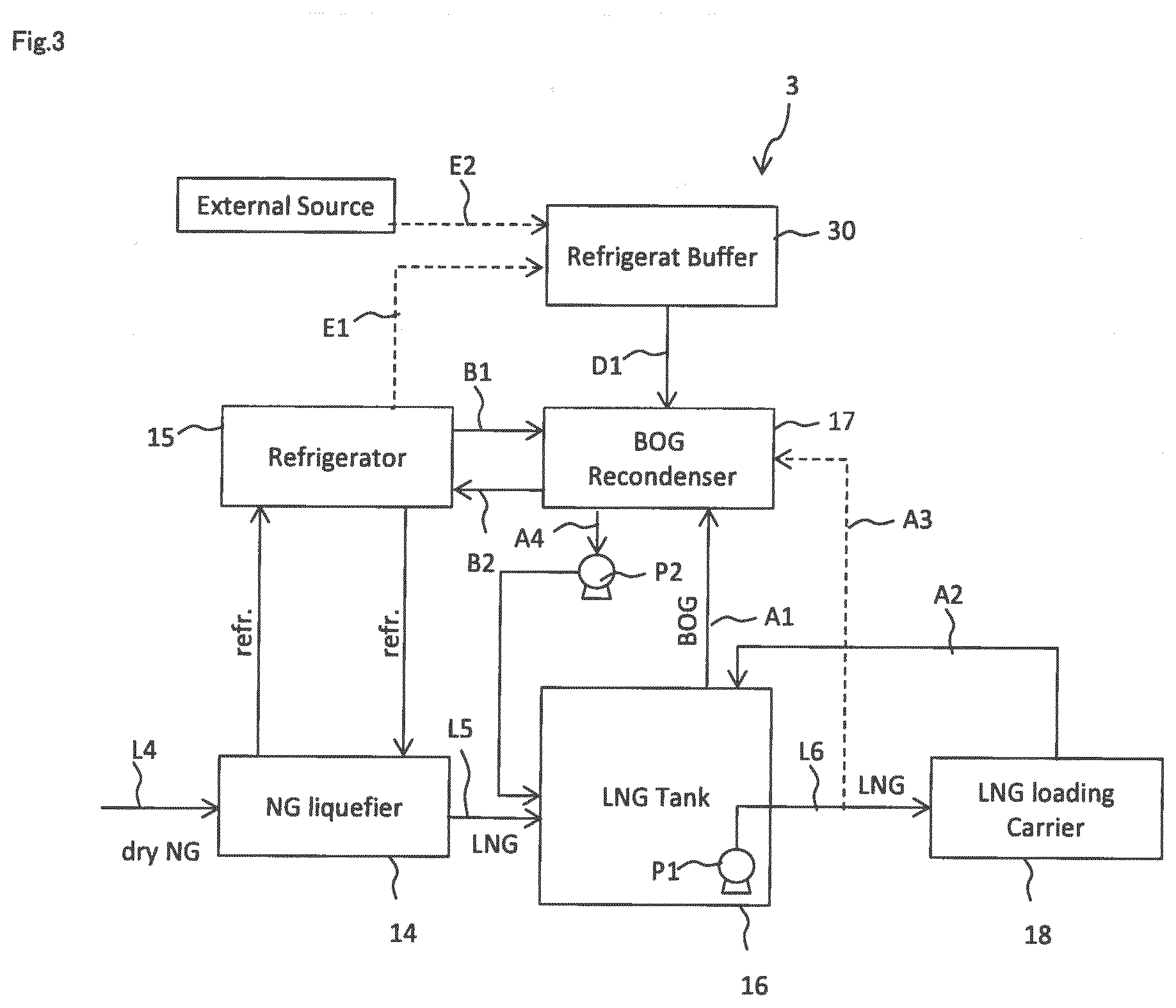
[0115] The recondenser 17 of the LNG production system 3 of embodiment 3 can perform a first recondensation processing of liquefying BOG by the refrigerant fed from the refrigerator 15, and a second recondensation processing that liquefies BOG by the refrigerant fed from the refrigerator 15 and a refrigerant fed from a refrigerant buffer 30 in order to process more BOG than BOG at the time of the first recondensation processing by switching the first and the second recondensation processings to each other.
[0116] In the refrigerant buffer 30, the refrigerant is supplied from the refrigerator 15 through a first supply line E1 and/or the refrigerant is supplied from an external refrigerant source through a second supply line E2 and is stored in advance. When the recondenser 17 is operated, the refrigerant is introduced into the recondenser 17 through a buffer line D1 from the refrigerant buffer 30.
[0117] The recondenser 17 has a switch control section (not illustrated) that switches the first recondensation processing and the second recondensation processing to each other.
[0118] When BOG is transferred to the LNG carrier 18, the switch control section can switch from the first recondensation processing to the second recondensation processing in response to a timing of start of transfer that is scheduled, or a timing at which a detecting section detects that LNG is transferred from the LNG tank 16, for example. As the detecting section, there are cited a detecting section that detects that the transportation ship enters a harbor, a detecting section that detects that the automatic on-off valve of the transfer line L6 opens, a detecting section that uses a control signal for controlling the automatic on-off valve as a detection signal, a detecting section that detects that a measurement result of a flow meter disposed in the transfer line L6 reaches a threshold value or more and the like.
[0119] Further, the switch control section can switch from the first recondensation processing to the second recondensation processing when a pressure value of the inside of the LNG tank 16 measured by the pressure gauge, or a pressure value measured by a pressure gauge disposed in at least any one of the feed line A1, the recovery line A2 and the feed line A3 reaches a predetermined value or more.
[0120] An example of the recondenser 17 of embodiment 3 will be described with FIG. 4C. The recondenser 17 has a first heat exchanger 172 and a second heat exchanger 174 in an internal space 173 thereof. A refrigerant is introduced into the first heat exchanger 172 from the refrigerator 15 at a time of the first recondensation processing, and cools BOG. When a generation amount of BOG is large, the switch control section switches from the first recondensation processing to the second recondensation processing. While the first heat exchanger 172 is operated, the second heat exchanger 174 is further operated. The refrigerant is introduced into the second heat exchanger 174 through the buffer line D1 from the refrigerant buffer 30. Thereby, cooling by the two heat exchangers is executed, so that at a peak time (for example, in a case of processing a large amount of BOG that is generated when LNG is fed into the LNG transport ship, for example) at which the amount of BOG that is fed is larger than the amount of BOG at a normal time, BOG is also effectively cooled to be converted into LNG and the LNG can be returned to the LNG tank 16. Note that the refrigerant that is used in the second heat exchanger 174 is configured to join the refrigerant return line B2 of the first heat exchanger 172 through a refrigerant return line D2, but the present invention is not limited to this, and the refrigerant return line D2 may be connected to the refrigerator 15.
[0121] Further, when BOG is fed to the LNG carrier 18, the switch control section can switch from the second recondensation processing to the first recondensation processing in response to a timing of end of transfer that is scheduled, or timing at which a detecting section detects that LNG transfer from the LNG tank 16 is completed, for example. As the detecting section, there are cited a detecting section that detects that the automatic on-off valve in the transfer line L6 is closed, a detecting section that detects the control signal that controls the automatic on-off valve as a detection signal, a detecting section that detects that the measurement result of the flow meter disposed in the transfer line L6 becomes a threshold value or less and the like.
[0122] Further, the switch control section can switch from the second recondensation processing to the first recondensation processing when a pressure value of the inside of the LNG tank 16 measured by the pressure gauge, or a pressure value measured by a pressure gauge disposed in at least one of the feed line A1, the recovery line A2 and the feed line A3 becomes less than a predetermined value.
Other Embodiments
[0123] In the above described embodiments, two heat exchangers are disposed in the recondenser 17, and cooling capabilities of the heat exchangers may be the same or different.
[0124] In the present embodiment, a combination of the refrigerant buffer and the heat exchanger is provided to be one, but the present invention is not limited to this, and two or more combinations may be provided.
Embodiment 4
[0125] An LNG production system 5 in embodiment 4 will be described with reference to FIGS. 5A to 5B. Components with the same reference signs as those in the LNG production system 1 of embodiment 1 have the same functions, and therefore, explanation of the components will be omitted, or will be made briefly.
[0126] In embodiment 4, the refrigerator in the LNG production system is not used, but LNG in the LNG tank is used. That is, in embodiment 4, LNG is sub-cooled to a predetermined temperature by a refrigerant, and LNG is fed to the recondenser to be brought into contact with BOG to liquefy BOG.
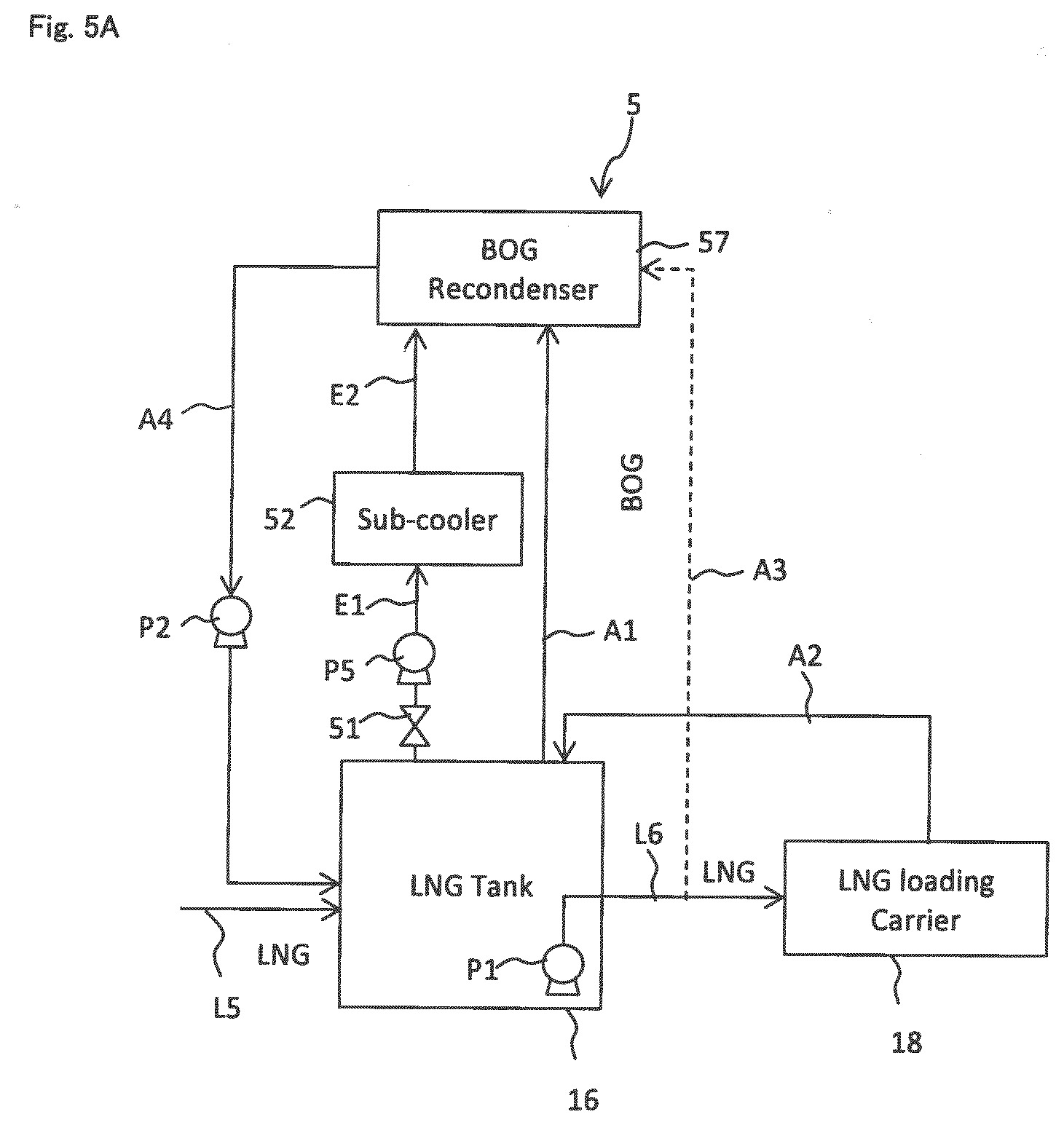
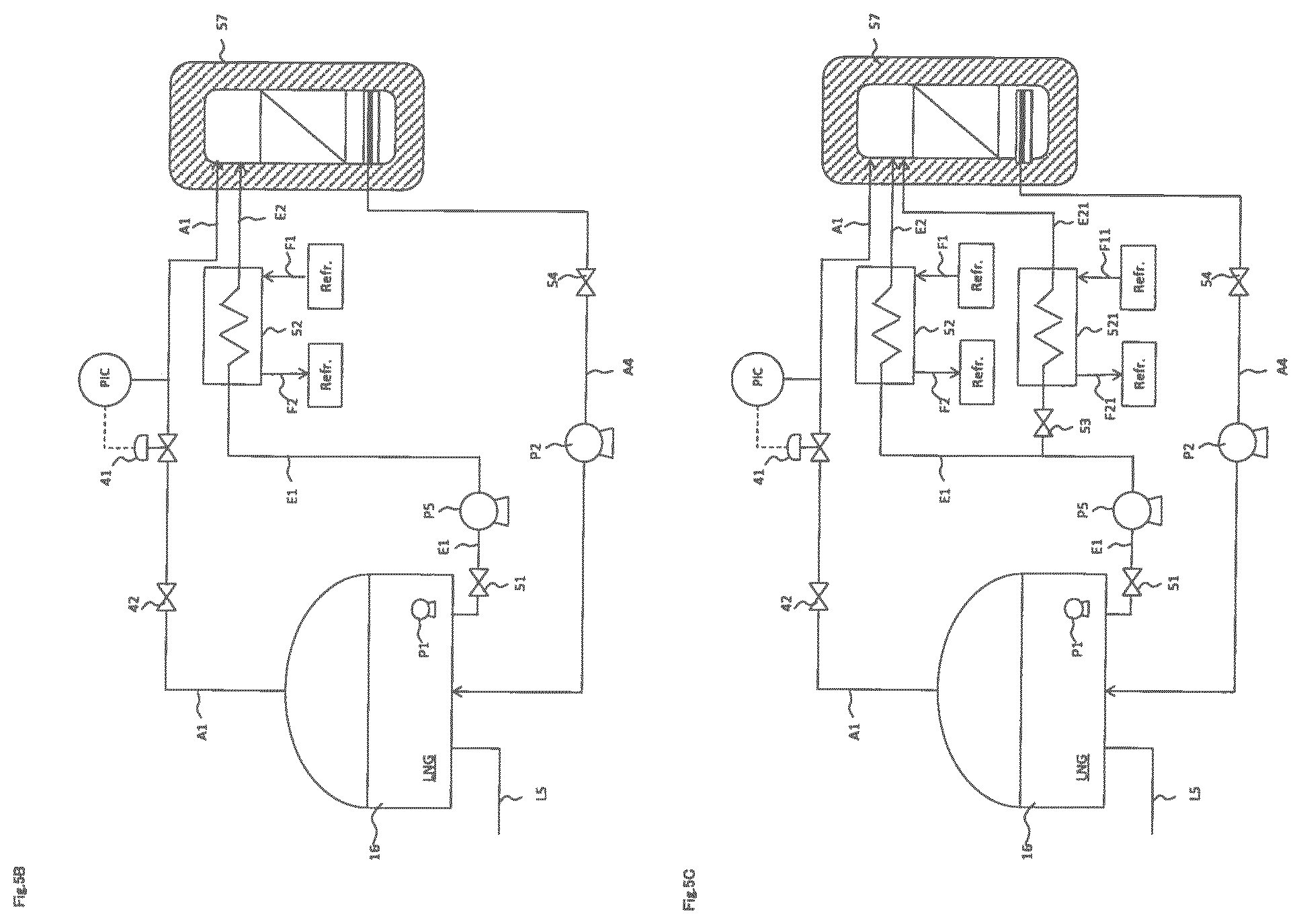
[0127] Embodiment 4 has a first feed line A1 that feeds BOG from the LNG tank 16, an LNG lead-out line E1 that leads out LNG from the LNG tank 16, a sub-cooler 52 that cools LNG with the refrigerant, a recondenser 57 that liquefies BOG that is fed through the first feed line A1 for BOG by LNG that is cooled in the sub-cooler 52, under a pressure lower than the operating pressure of the LNG tank 16, and a return line A4 that returns LNG that is BOG liquefied in the recondenser 57 to the LNG tank 16. The respective components will be described in detail hereunder.
[0128] The first feed line A1 may be provided with a safety valve (not illustrated) for a time when the pressure in the LNG tank 16 becomes abnormally high. Further, the first feed line A1 is provided with an automatic on-off valve 42 and a pressure regulating valve 41 for performing feeding control of BOG to the condenser 10.
[0129] The operating pressure in the LNG tank 16 is an average of 1.2 barA (120 KPaA) in absolute pressure, and is controlled within .+-.15% as an upper and lower limit values. When a large amount of BOG is generated, the tank internal pressure becomes high. The tank internal pressure is measured by a pressure gauge, and a valve control section (not illustrated) controls opening and closing of the automatic on-off valve 42 based on a measurement result (conversion result) thereof. For example, when the tank internal pressure becomes 1.3 times as high as 1.2 barA (120 KPaA), BOG is fed to the recondenser 57. The pressure regulating valve 41 measures a pipe internal pressure of the first feed line A1, and controls a valve opening degree based on a measurement result.
[0130] LNG is introduced into the sub-cooler 52 through the LNG lead-out line E1 from the LNG tank 16. The valve control section (not illustrated) performs opening and closing control of the automatic on-off valve 51 provided in the LNG lead-out line E1, and controls a liquid feed pump P5, whereby LNG is fed to the sub-cooler 52 from the LNG tank 16, and is fed to the recondenser 57 in a subsequent stage. The in-tank liquid feed pump P1 may be configured to feed LNG, instead of the liquid feed pump P5.
[0131] The refrigerant in the sub-cooler 52 can be a medium having a temperature lower than the boiling point of LNG, and LN2 is used in the present embodiment. LN2 is introduced into the sub-cooler 52 through a refrigerant line F1 from an LN2 source (LN2 tank, for example), and is used as a cold source for cooling LNG passing through an inside of the sub-cooler 52. LN2 may be gasified, or may be discharged as a fluid in which a liquid and gas are mixed, when LN2 is discharged from the sub-cooler 52 through a discharge line F2. The fluid (LN2 and/or GN2) which is discharged may be subjected to discharge treatment to the atmosphere or may be subjected to recycle processing.
[0132] In the sub-cooler 52, LNG may be controlled to have a temperature higher than the LNG solidifying point by a pressure regulating valve (not illustrated), or a flow rate regulating valve (not illustrated) that is installed in the refrigerant line F1 in which the refrigerant (LN2) flows.
[0133] An internal pressure of the recondenser 57 is controlled to be a pressure lower than the operating pressure (an average of 1.2 barA (120 KPaA) in the absolute pressure) of the LNG tank 16 in the BOG recondensation processing. The internal pressure of the recondenser 57 is measured by the pressure gauge, and is regulated to be lower than the operating pressure of the LNG tank 16.
[0134] In the present embodiment, LNG that is cooled in the sub-cooler 52 contacts BOG in the recondenser 57, whereby the volume of BOG decreases by liquefaction, and the pressure in the recondenser 57 is reduced. During operation, the low pressure state is kept by the cooled LNG being continuously supplied. The internal pressure of the recondenser 57 is regulated by controlling the flow rate of the cooled LNG. A flow rate regulating valve is provided in an LNG feed line E2 between the sub-cooler 52 and the recondenser 57, and the flow rate of LNG may be controlled by the flow rate regulating valve in accordance with a measurement result of the pressure gauge that measures the internal pressure of the above described recondenser 57, the flow rate of LNG may be controlled by controlling the opening degree of an automatic on-off valve 51, or both of them may be controlled.
[0135] The BOG that is introduced into the recondenser 57 is brought into contact with cooled LNG, whereby BOG is liquefied to be LNG, and LNG accumulates on a bottom of the recondenser 57. As a method for bringing both BOG and LNG into contact with each other, there are means of spraying LNG cooled in the sub-cooler 52 by shower, means of bringing both of them into contact with each other by using a filler, and the like.
[0136] A lower part of the recondenser 57 and the return line A4 are connected. The valve control section (not illustrated) performs on-off control of an automatic on-off valve 54 provided in the return line A4, and controls the liquid feed pump P2, whereby the valve control section can feed LNG back to the LNG tank 16 from the recondenser 57.
[0137] A processing procedure of the recondensation processing of BOG will be described hereunder. The respective valves 41 to 42, 51 and 54 are in closed states except for the recondensation processing.
(1) Feed the refrigerant (LN2, for example) to the sub-cooler 52, when the tank internal pressure of the LNG tank 16 exceeds a first threshold value. (2) When the sub-cooler 52 reaches a predetermined temperature or less, feed LNG to the sub-cooler 52 from the LNG tank 16, and is cooled. For example, a temperature of the LNG which is cooled is preferably set at a temperature higher than the LNG solidifying point, and lower than the temperature of LNG in the LNG tank 16. The temperature of LNG which is cooled may be set based on the amount of BOG and the amount of LNG which is cooled. (3) Feed the cooled LNG to the recondenser 57, and pre-cool the recondenser 57. The automatic on-off valve 54 of the return line A4 is closed. (4) When the tank internal pressure of the LNG tank 16 exceeds a second threshold value (the second threshold value>the first threshold value), open the automatic on-off valve 42 and the pressure regulating valve 41, and introduce BOG to the recondenser 57 from the LNG tank 16. (5) The recondenser 57 is pre-cooled, and the cooled LNG is introduced into the recondenser 57 with BOG, whereby BOG is cooled and changes state to LNG, and the LNG accumulates on the bottom of the recondenser 57. (6) When LNG that accumulates on the bottom of the recondenser 57 reaches a predetermined amount (or at a predetermined timing), open the automatic on-off valve 54, control the liquid feed pump P2, and feed LNG to the LNG tank 16 from the recondenser 57. (7) Close the respective valves after the recondensation processing ends.
[0138] It is also assumed that a condition of (4) (the tank internal pressure>the second threshold value) is established during processing of (1) to (3), so that BOG may be configured to be discharged from the LNG tank 16 with a safety valve (not illustrated), or BOG may be discharged to external air by a vent not illustrated.
[0139] The above described "first threshold value" is the pressure that is 1.26 times as high as 1.2 barA (120 KPaA), for example.
[0140] The above described "second threshold value" is the pressure that is 1.3 times as high as 1.2 barA (120 KPaA), for example.
Embodiment 5
[0141] An LNG production system of embodiment 5 will be described with use of FIG. 5C. Components with the same reference signs as those in the LNG production systems 1 and 5 of embodiments 1 and 4 have the same functions, and therefore, explanation of the components will be omitted, or will be made briefly.
[0142] In embodiment 5, a first and second sub-coolers are disposed, and a first recondensation processing of liquefying BOG by a refrigerant fed from the first sub-cooler 52, and a second recondensation processing of liquefying BOG by the refrigerant fed from the first sub-cooler 52 and a refrigerant fed from a second sub-cooler 521 in order to process more BOG than BOG at the time of the first recondensation processing are switched. According to the embodiment, in the case of processing BOG in an amount in a predetermined range (a flow rate per unit time) or of a pressure value in a predetermined range set in advance, the first recondensation processing (processing of liquefying BOG with LNG cooled in the first sub-cooler) is executed, and in the case of processing BOG exceeding the amount in the predetermined range or of the pressure value in the predetermined range described above, the second recondensation processing (simultaneously performing the processing of liquefying BOG by LNG cooled in the second sub-cooler while keeping the processing of liquefying BOG by LNG cooled in the first sub-cooler) can be executed.
[0143] The switch control section (not illustrated) may switch from the first recondensation processing to the second recondensation processing in the case of transferring BOG to the LNG carrier, or may switch from the first recondensation processing to the second recondensation processing when the pressure value that is measured by the pressure gauge disposed in the LNG tank or in the feed line A1 that feeds BOG to the recondenser 57 reaches a predetermined value or more.
[0144] In the present embodiment, the refrigerant which is fed to the first sub-cooler 52, and the refrigerant which is fed to the second sub-cooler 521 may be the same refrigerants, or may be different refrigerants. For example, as the refrigerant to the first sub-cooler 52, a mixture such as hydrocarbon can be cited, and as the refrigerant to the second sub-cooler 521, nitrogen and the like are cited.
[0145] The switch control section can perform switching from the first recondensation processing to the second recondensation processing in the timing of embodiment 3 described above. When the processing is switched to the second recondensation processing, the valve control section (not illustrated) performs opening and closing control of a sluice valve 53, feeds LNG to the second sub-cooler 521, and feeds LNG to the recondenser 57 in the subsequent stage. That is, in the first recondensation processing, cooled LNG is fed to the recondenser 57 through the LNG feed line E2 from the first sub-cooler 52, but the processing is switched to the second recondensation processing, and cooled LNG is fed to the recondenser 57 through an LNG feed line E21 from the second sub-cooler 521, in addition to the cooled LNG being fed to the recondenser 57 from the first sub-cooler 52.
[0146] The refrigerant of the second sub-cooler 521 can be any medium with a temperature lower than the boiling point of LNG, and LN2 is used in the present embodiment. LN2 is introduced into the second sub-cooler 521 through a refrigerant line F11 from an LN2 source (an LN2 tank, for example), and is used as a cold source for cooling LNG that passes through an inside of the second sub-cooler 521. LN2 may be gasified, or may be discharged as a fluid in which a liquid and gas are mixed, when the LN2 is discharged through a discharge line F21 from the second sub-cooler 521. The fluid (LN2 and/or GN2) which is discharged may be subjected to discharge treatment into the atmosphere, or may be subjected to recycling processing. Further, in the second sub-cooler 521, LNG may be controlled to have a temperature higher than the LNG solidifying point, by a pressure regulating valve (not illustrated) or a flow rate regulating valve (not illustrated) that is installed in a refrigerant line F11 in which the refrigerant (LN2) flows.
Other Embodiments
[0147] In embodiments 4 and 5 described above, the respective automatic on-off valves, pressure regulating valves and liquid feed pumps are provided in the respective lines, but some or all of them may be omitted in accordance with the use purpose without being limited to the above described dispositions.
[0148] Further, in embodiments 4 and 5 described above, in the BOG recondensation processing, LNG that is cooled is fed to pre-cool the recondenser 57 before BOG is fed into the recondenser 57, but the present invention is not limited to this, and cooled LNG and BOG may be fed together. In that case, a feeding amount (VL) of the cooled LNG and a feeding amount (VB) of BOG may be controlled to VL>VB. The flow rate regulating valves may be provided in the respective LNG introduction line E1, line E2 and first feed line A1 for BOG to perform flow rate control of the respective feeding amounts.
[0149] Further, in embodiments 4 and 5 described above, the liquid feed pump P2 is provided in the return line A4, but a configuration in which the liquid feed pump is not provided in the return line A4 may be adopted. LNG changed in state from BOG in the recondenser 57 may be fed into the LNG tank 16 by the gravity.
[0150] Further, the refrigerant in the aforementioned second sub-cooler 521 may be supplied from a refrigerant buffer in which the refrigerant is stored in advance.
[0151] In each of all the embodiments described above, the pump P1 is of an in-tank type, but the pump P1 is not limited to this, and the pump P1 may be a pump disposed on the transfer line L6.
REFERENCE SIGNS LIST
[0152] 1 LNG production system
[0153] 14 Cooling device
[0154] 15 Refrigerator
[0155] 16 LNG tank
[0156] 17 Recondenser
[0157] 18 LNG carrier
[0158] L6 Transfer line
* * * * *
D00000
D00001
D00002
D00003
D00004
D00005
D00006
D00007
XML
uspto.report is an independent third-party trademark research tool that is not affiliated, endorsed, or sponsored by the United States Patent and Trademark Office (USPTO) or any other governmental organization. The information provided by uspto.report is based on publicly available data at the time of writing and is intended for informational purposes only.
While we strive to provide accurate and up-to-date information, we do not guarantee the accuracy, completeness, reliability, or suitability of the information displayed on this site. The use of this site is at your own risk. Any reliance you place on such information is therefore strictly at your own risk.
All official trademark data, including owner information, should be verified by visiting the official USPTO website at www.uspto.gov. This site is not intended to replace professional legal advice and should not be used as a substitute for consulting with a legal professional who is knowledgeable about trademark law.