Solid Fuel Burner
WATANABE; Junya ; et al.
U.S. patent application number 16/541914 was filed with the patent office on 2020-02-20 for solid fuel burner. The applicant listed for this patent is Mitsubishi Hitachi Power Systems, Ltd.. Invention is credited to Akira BABA, Kosuke KITAKAZE, Kenji KIYAMA, Koji KURAMASHI, Kenichi OCHI, Junya WATANABE.
| Application Number | 20200056780 16/541914 |
| Document ID | / |
| Family ID | 69523813 |
| Filed Date | 2020-02-20 |


| United States Patent Application | 20200056780 |
| Kind Code | A1 |
| WATANABE; Junya ; et al. | February 20, 2020 |
Solid Fuel Burner
Abstract
The present invention provides a solid fuel burner which ensures ignition performance and flame holding performance of a fuel nozzle. The present invention provides a solid fuel burner which achieves cost reduction by simplifying the structure of the fuel nozzle, for example, and which ensures the ignition performance and flame holding performance of the fuel nozzle. Further, the present invention provides a burner which enables stable combustion by both solid fuel and oil combustion with the suppression of soot and dust and mist generated during the oil start-up envisaged. The solid fuel burner of the present invention includes: a fuel nozzle straight tube portion allowing a mixing gas of a solid fuel and its carrier gas to flow therethrough; a fuel nozzle throttling portion narrowing a flow passage of the mixing gas passed through the fuel nozzle straight tube portion; a fuel nozzle diffusion portion horizontally expanding the flow passage of the mixing gas passed through the fuel nozzle throttling portion; a fuel nozzle outlet portion connected to the fuel nozzle diffusion portion and having an outlet flattened in shape; a ring-shaped outer peripheral flame stabilizer disposed on an outer periphery of the fuel nozzle outlet portion; and an inner flame stabilizer disposed in the fuel nozzle outlet portion and horizontally dividing the mixing gas passed through the fuel nozzle diffusion portion.
| Inventors: | WATANABE; Junya; (Yokohama-shi, JP) ; KURAMASHI; Koji; (Yokohama-shi, JP) ; BABA; Akira; (Yokohama-shi, JP) ; KITAKAZE; Kosuke; (Yokohama-shi, JP) ; OCHI; Kenichi; (Yokohama-shi, JP) ; KIYAMA; Kenji; (Yokohama-shi, JP) | ||||||||||
| Applicant: |
|
||||||||||
|---|---|---|---|---|---|---|---|---|---|---|---|
| Family ID: | 69523813 | ||||||||||
| Appl. No.: | 16/541914 | ||||||||||
| Filed: | August 15, 2019 |
| Current U.S. Class: | 1/1 |
| Current CPC Class: | F23C 3/008 20130101; F23C 7/006 20130101; F23D 1/005 20130101; F23D 1/04 20130101; F23C 7/008 20130101; F23D 2201/10 20130101; F23D 2201/20 20130101 |
| International Class: | F23D 1/00 20060101 F23D001/00; F23C 7/00 20060101 F23C007/00; F23C 3/00 20060101 F23C003/00 |
Foreign Application Data
| Date | Code | Application Number |
|---|---|---|
| Aug 20, 2018 | JP | 2018-153865 |
Claims
1. A solid fuel burner comprising: a fuel nozzle straight tube portion allowing a mixing gas of a solid fuel and its carrier gas to flow therethrough; a fuel nozzle throttling portion narrowing a flow passage of the mixing gas passed through the fuel nozzle straight tube portion; a fuel nozzle diffusion portion horizontally expanding the flow passage of the mixing gas passed through the fuel nozzle throttling portion; a fuel nozzle outlet portion connected to the fuel nozzle diffusion portion and having an outlet flattened in shape; a ring-shaped outer peripheral flame stabilizer disposed on an outer periphery of the fuel nozzle outlet portion; and an inner flame stabilizer disposed in the fuel nozzle outlet portion and horizontally dividing the mixing gas passed through the fuel nozzle diffusion portion.
2. The solid fuel burner according to claim 1, comprising a guide sleeve disposed on an outer side of the outer peripheral flame stabilizer.
3. The solid fuel burner according to claim 2, comprising a top-bottom guide sleeve disposed vertically with respect to an outer periphery of the guide sleeve.
4. The solid fuel burner according to claim 3, wherein the fuel nozzle throttling portion is a venturi type which is circumferentially narrowed.
5. The solid fuel burner according to claim 3, wherein the fuel nozzle throttling portion has a structure which is narrowed only in the vertical direction.
6. The solid fuel burner according to claim 5, comprising a horizontal vane disposed in the fuel nozzle diffusion portion and serving to disperse the mixing gas horizontally outward.
7. The solid fuel burner according to claim 5, comprising a swirling vane disposed in the fuel nozzle straight tube portion and serving to stir the mixing gas.
8. The solid fuel burner according to claim 5, further comprising: a pipe disposed on an upstream side of the fuel nozzle straight tube portion and including a bending portion connected to the fuel nozzle straight tube portion; and a guide disposed in the bending portion of the pipe and serving to centrifugally divide the mixing gas.
9. The solid fuel burner according to claim 6, comprising: a pipe disposed on an upstream side of the fuel nozzle straight tube portion and including a bending portion connected to the fuel nozzle straight tube portion; and a particle dispersion plate disposed in the fuel nozzle straight tube portion and serving to disperse the mixing gas.
10. The solid fuel burner according to claim 1, wherein a horizontal cross section of the inner flame stabilizer takes a triangular prism defining isosceles triangle.
11. The solid fuel burner according to claim 1, wherein the inner flame stabilizer is provided with a recess portion on its backside on a downstream side of a fuel flow and/or air flow direction.
12. The solid fuel burner according to claim 1, wherein a plate is arranged with the inner flame stabilizer such that the stabilizer takes a V-shape structure.
13. The solid fuel burner according to claim 12, wherein an baffle plate is disposed at a tip end of a plate member taking the V-shape structure so as to enlarge a cross-sectional area of the tip end.
14. The solid fuel burner according to claim 1, wherein a horizontal cross section of the inner flame stabilizer has a pentagonal prism structure.
15. The solid fuel burner according to claim 11, wherein the inner flame stabilizer is provided with the recess portion including a vertical notch on its backside on the downstream side of the fuel flow and/or air flow direction.
16. The solid fuel burner according to claim 11, wherein the inner flame stabilizer is provided with air inlets to supply air into the recess portion.
Description
CLAIM OF PRIORITY
[0001] The present application claims priority from Japanese Patent application serial no. 2018-153865, filed on Aug. 20, 2018, the content of which is hereby incorporated by reference into this application.
TECHNICAL FIELD
[0002] The present invention relates to a solid fuel burner.
BACKGROUND ART
[0003] A background art of this field is set forth in Japanese Patent Application Laid-Open No. Hei 10-220707 (Patent Literature 1). This patent literature discloses a structure which includes: an outer peripheral flame stabilizing ring disposed on an outer periphery of a burner; an inner flame stabilizer disposed in a pulverized coal fuel pipe and equipped with a flame stabilizing plate for drawing a high temperature gas from the outer periphery of the burner into a central part of the burner; and a separator disposed on a burner front-stream side of the inner flame stabilizer. The structure is adapted to increase a pulverized coal flow volume at the center of the burner and to decrease the pulverized coal flow volume on the outer periphery of the burner.
[0004] Another background art of this field is set forth in Japanese Patent Application Laid-Open No. 2014-055759 (Patent Literature 2). This patent literature discloses a combustor which includes pulverized coal burners arranged in plural rows and plural columns on at least one surface of furnace walls. The pulverized coal burner includes a pulverized coal nozzle which includes a venturi including the throttling portion and the concentrator in the fuel flow passage. In the pulverized coal nozzle, a portion having a circular transverse cross section extends to the vicinity of the throttling portion, from which the transverse cross section is progressively flattened in the horizontal direction so that the nozzle has the maximum degree of flatness at an opening of the furnace wall. The pulverized coal burners are arranged such that width sides of the flattened nozzles are properly directed in a vertical direction or horizontal direction.
SUMMARY OF THE INVENTION
[0005] The above-described Patent Literature 1 discloses the solid fuel burner including the inner flame stabilizer and the outer peripheral flame stabilizing ring, while the above-described Patent Literature 2 discloses the pulverized coal burner including the pulverized coal nozzle which is flattened at the outlet. The solid fuel burner stated in Patent Literature 1 and the pulverized coal burner stated in Patent Literature 2 may encounter the following problem. In a case where the burner grows in size, an ignition area relative to fuel injection becomes smaller, which may result in instable ignition or flame holding.
[0006] It is therefore an object of the present invention to provide a solid fuel burner featuring a fuel nozzle which ensures stable ignition performance and flame holding performance. The solid fuel burner of the present invention can be applied to a case where the burner has a large capacity, or a case where a flame retardant fuel having a small amount of volatile matter, for example, solid fuel such as anthracite or petroleum coke. In addition, since the average particle size of the solid fuel supplied to the burner is large, it can be applied to a fuel, for example, biomass, for which floating combustion within a boiler furnace is harder than pulverized coal. Further, the present invention provides a solid fuel burner which achieves cost reduction by simplifying the structure of the fuel nozzle and mitigate environmental burden as represented by NO.sub.x and CO and enables efficient combustion such as reducing unburned carbon in the fly ashes and the CO content of the flue gas. Further, the present invention provides a solid fuel burner in which the solid fuel burner and a start-up oil burner are coaxially arranged and which is reducing soot and dust, oil mist and CO during operation.
[0007] For achieving the above object, a solid fuel burner is characterized in including: a fuel nozzle straight tube portion allowing a mixing gas of a solid fuel and its carrier gas to flow therethrough; a fuel nozzle throttling portion narrowing a flow passage of the mixing gas passed through the fuel nozzle straight tube portion; a fuel nozzle diffusion portion horizontally expanding the flow passage of the mixing gas passed through the fuel nozzle throttling portion; a fuel nozzle outlet portion connected to the fuel nozzle diffusion portion and having an outlet flattened in shape; a ring-shaped outer peripheral flame stabilizer disposed on an outer periphery of the fuel nozzle outlet portion; and an inner flame stabilizer disposed in the fuel nozzle outlet portion and horizontally dividing the mixing gas passed through the fuel nozzle diffusion portion.
[0008] The present invention can provide the solid fuel burner which ensures the ignition performance and flame holding performance of the fuel nozzle in future too. The present invention can provide the solid fuel burner which achieves cost reduction by simplifying the structure of the fuel nozzle and ensure the ignition performance and flame holding performance of the fuel nozzle.
[0009] The problems, components and effects other than those described above will become apparent from the description of the following examples hereof.
BRIEF DESCRIPTION OF THE DRAWINGS
[0010] FIG. 1A is an illustrative diagram showing a vertical cross section of a solid fuel burner according to Example 1 hereof as taken on the axis thereof.
[0011] FIG. 1B is an illustrative diagram showing a horizontal cross section of the solid fuel burner according to Example 1 hereof as taken on the axis thereof.
[0012] FIG. 2A is an illustrative diagram showing a vertical cross section of a solid fuel burner according to Example 2 hereof as taken on the axis thereof.
[0013] FIG. 2B is an illustrative diagram showing a horizontal cross section of the solid fuel burner according to Example 2 hereof as taken on the axis thereof.
[0014] FIG. 3A is an illustrative diagram showing a vertical cross section of a solid fuel burner according to Example 3 hereof as taken on the axis thereof.
[0015] FIG. 3B is an illustrative diagram showing a horizontal cross section of the solid fuel burner according to Example 3 hereof as taken on the axis thereof.
[0016] FIG. 4A is an illustrative diagram showing a vertical cross section of a solid fuel burner according to Example 4 hereof as taken on the axis thereof.
[0017] FIG. 4B is an illustrative diagram showing a horizontal cross section of the solid fuel burner according to Example 4 hereof as taken on the axis thereof.
[0018] FIG. 5A is an illustrative diagram showing a vertical cross section of a solid fuel burner according to Example 5 hereof as taken on the axis thereof.
[0019] FIG. 5B is an illustrative diagram showing a horizontal cross section of the solid fuel burner according to Example 5 hereof as taken on the axis thereof.
[0020] FIG. 6A is an illustrative diagram showing a vertical cross section of a solid fuel burner according to Example 6 hereof as taken on the axis thereof.
[0021] FIG. 6B is an illustrative diagram showing a horizontal cross section of the solid fuel burner according to Example 6 hereof as taken on the axis thereof.
[0022] FIG. 7A is an illustrative diagram showing an example of the inner flame stabilizer which is disposable in any one of the solid fuel burners according to Example 1 to 6 hereof.
[0023] FIG. 7B is an illustrative diagram showing an example of the inner flame stabilizer which is disposable in any one of the solid fuel burners according to Example 1 to 6 hereof.
[0024] FIG. 7C is an illustrative diagram showing an example of the inner flame stabilizer which is disposable in any one of the solid fuel burners according to Example 1 to 6 hereof.
[0025] FIG. 7D is an illustrative diagram showing an example of the inner flame stabilizer which is disposable in any one of the solid fuel burners according to Example 1 to 6 hereof.
[0026] FIG. 7E is an illustrative diagram showing an example of the inner flame stabilizer which is disposable in any one of the solid fuel burners according to Example 1 to 6 hereof.
[0027] FIG. 7F is an illustrative diagram showing an example of the inner flame stabilizer which is disposable in any one of the solid fuel burners according to Example 1 to 6 hereof.
[0028] FIG. 7G is an illustrative diagram showing an example of the inner flame stabilizer which is disposable in any one of the solid fuel burners according to Example 1 to 6 hereof, in which the detail of the inner flame stabilizer in FIG. 7D, the flow of the solid fuel and the injection direction of the start-up oil fuel are shown.
DETAILED DESCRIPTION OF EMBODIMENTS
[0029] The examples of the present invention will hereinbelow be described with reference to the accompanying drawings. Equal or similar reference numerals are assigned to equal or similar components, and explanation of overlapping components may be omitted.
First Embodiment
[0030] In combustors using solid fuels such as coal fired boilers, the solid fuel burner for use in the combustors is required to ensure stable ignition and flame holding in order to achieve the reduction of harmful emissions such as nitrogen oxides (NOx) and the increase in combustion efficiency. To ensure the stable ignition and flame holding, it is important to install a flame stabilizer in a fuel nozzle of a solid fuel burner and to supply the flame stabilizer with a fuel stream (particles of solid fuel) having sufficiently high density. Particularly, in a case where the solid fuel burner is increased in size so that a large ignition area is required or a case where the solid fuel burner operates under low load during load fluctuation, the stable ignition and flame holding is necessary.
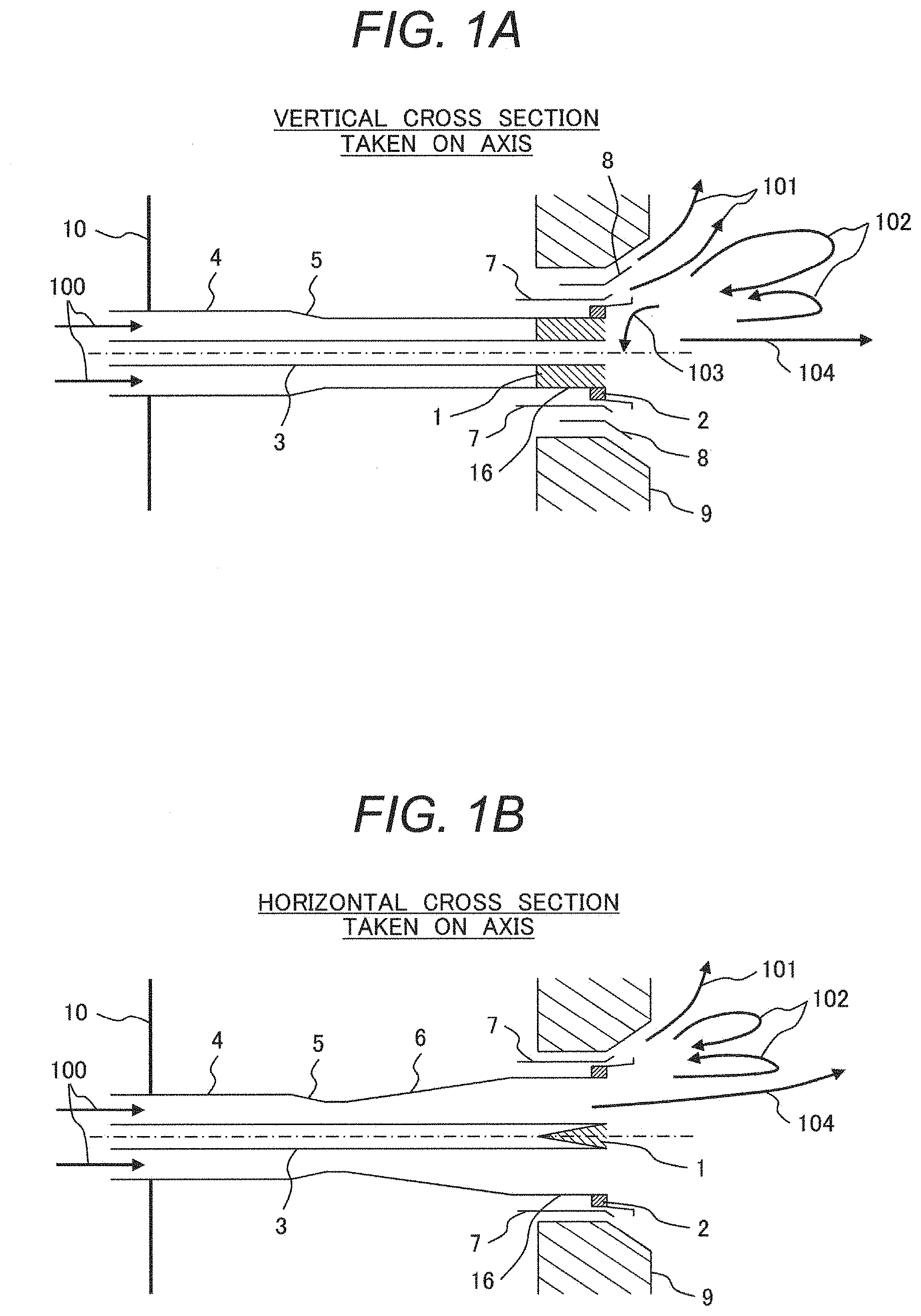
[0031] FIG. 1A is an illustrative diagram showing a vertical cross section of a solid fuel burner according to Example 1 hereof as taken on the axis thereof. FIG. 1B is an illustrative diagram showing a horizontal cross section of the solid fuel burner according to Example 1 hereof as taken on the axis thereof.
[0032] The solid fuel burner according to the example includes: a fuel nozzle straight tube portion 4 (hereinafter, simply referred to as "straight tube portion") which allows a mixing gas 100 of a solid fuel and its carrier gas to flow therethrough; a fuel nozzle throttling portion 5 (hereinafter, simply referred to as "throttling portion") which narrows a flow passage of the mixing gas 100 passed through the straight tube portion 4 so as to accelerate the mixing gas 100; a fuel nozzle diffusion portion 6 (hereinafter, simply referred to as "diffusion portion") which flows and slows the mixing gas 100 accelerated as passed through the throttling portion 5 and horizontally expands the flow passage of the mixing gas 100; and a fuel nozzle outlet portion 16 (hereinafter, simply referred to as "outlet portion") which is connected to the diffusion portion 6 and ejects the mixing gas 100 passed through the diffusion portion 6 into a furnace.
[0033] An outlet of the outlet portion 16 has a flat configuration which is expanded in horizontal width. The throttling portion 5 is a venturi type which is circumferentially narrowed.
[0034] The straight tube portion 4, the throttling portion 5, the diffusion portion 6 and the outlet portion 16 constitute the fuel nozzle, defining the flow passage of the mixing gas 100.
[0035] A wind box 10 for introducing combustion air is disposed on an outer periphery of the fuel nozzle (straight tube portion 4, throttling portion 5 and diffusion portion 6).
[0036] A guide sleeve 7 for discharging the combustion air into the furnace is disposed on an outer periphery of the outlet portion 16. A top-bottom guide sleeve 8 for discharging the combustion air to upper and lower areas of the furnace is disposed at upper and lower places of an outer periphery of the guide sleeve 7. Furnace walls 9 are disposed on transversely outer sides of the guide sleeve 7 and on vertically outer sides of the top-bottom guide sleeve 8 on the outer sides of the guide sleeve 7, respectively.
[0037] An outer peripheral flame stabilizer 2 shaped like a ring is disposed on the outer periphery of the outlet portion 16. It is noted that the guide sleeve 7 is disposed on an outer side from the outer peripheral flame stabilizer 2.
[0038] The outlet portion 16 is provided with an inner flame stabilizer 1 shaped like a wedge having an isosceles triangular cross section. The inner flame stabilizer 1 is singly disposed at a horizontally central position so as to horizontally divide the mixing gas 100 passed through the diffusion portion 6.
[0039] A central supporting rod 3 is disposed at a central part of fuel nozzle (straight tube portion 4, throttling portion 5, and diffusion portion 6). According to the example, the central supporting rod 3 is not provided with a particle concentrator for throwing the particles of the solid fuel (hereinafter, simply referred to as "particles") toward an outer periphery for concentration.
[0040] The mixing gas 100 ejected from the outlet portion 16 into the furnace forms a fuel jet flow 104. The combustion air discharged from the guide sleeve 7 and top-bottom guide sleeve 8 into the furnace as spreading circumferentially outward forms a combustion air jet flow 101.
[0041] A recirculation flow 102 is formed between the fuel jet flow 104 and the combustion air jet flow 101. The recirculation flow 102 is formed in the rear of the outer peripheral flame stabilizer 2. A high-temperature combustion gas resulting from fuel combustion in the furnace accumulates in the recirculation flow 102. The high-temperature combustion gas contacting with the fuel jet flow 104 causes immediate ignition of the particles in the rear of the outer peripheral flame stabilizer 2 and thus, flames are formed.
[0042] In the solid fuel burner according to the example, the outlet portion 16 has the flattened configuration having a short vertical (height) dimension and a long horizontal (width) dimension. The diffusion portion 6 is expanded in the horizontal direction but not in the vertical direction. That is, the diffusion portion 6 and the outlet portion 16 are formed in the flattened shape also at their connection portion.
[0043] In general, an opening (a jetting port of the fuel jet flow into the furnace) of the fuel nozzle of the solid fuel burner has a circular shape. In a case where the outlet portion of the solid fuel burner has the flattened configuration having a short vertical (height) dimension and a long horizontal (width) dimension, a flow passage of the combustion air jetted from an outer peripheral area of the outlet portion has an area which is vertically wide and horizontally narrow. Accordingly, the flow volume of the combustion air is large in the vertical area but small in the horizontal area.
[0044] The solid fuel burner of the example is provided with the top-bottom guide sleeve 8 only in the vertical area so as to guide the combustion air in the vertical area of the large flow volume to the outer peripheral area. In a case where the combustion air has a large flow volume, the combustion air with high kinetic momentum is jetted into the furnace so that a large recirculation flow 102 is vertically formed in the rear of the outer peripheral flame stabilizer 2.
[0045] The larger the magnitude of the recirculation flow 102 is, the more high-temperature combustion gas can be accumulated. Mixed with the fuel jet flow 104 and imparted thermal radiation, the recirculation flow 102 can provide stable ignition and flame holding of the solid fuel. Therefore, the fuel nozzle having the horizontally elongated flat configuration at the outlet portion 16 is capable of forming the large recirculation flow 102 in vertically upper and lower areas and achieving the stable ignition and flame holding.
[0046] The solid fuel burner according to the example has the inner flame stabilizer 1 so disposed as to horizontally divide the flow passage in the outlet portion 16. Namely, the inner flame stabilizer 1 is designed to horizontally divide the mixing gas 100 passed through the diffusion portion 6. The inner flame stabilizer 1 so disposed as to horizontally divide the flow passage in the outlet portion 16 plays a role as a bridge to interconnect the upper and lower parts of the outer peripheral flame stabilizer 2. By virtue of the effect of the fuel nozzle having the horizontally elongated flat configuration, a large recirculation flow 102 is formed at the upper and lower parts of the outer peripheral flame stabilizer 2 so that the high-temperature combustion gas is stably supplied to the vicinity of the outer peripheral flame stabilizer 2.
[0047] The high-temperature combustion gas in the large recirculation flow 102 can be drawn to the center in the rear of the outlet portion 16 by disposing the inner flame stabilizer 1 according to the example. That is, a high-temperature gas flow 103 can be formed so as to draw the high-temperature combustion gas to the center in the rear of the outlet portion 16. In this way, the high-temperature combustion gas drawn to the center in the rear of the outlet portion 16 permits even the small recirculation flow (not shown) in the rear of the inner flame stabilizer 1 to achieve the stable ignition and flame holding of the whole fuel jet flow up to the point where the divided fuel jet flow 104 is innermost ignited on the inner sides thereof.
[0048] The particles are concentrated toward the center of the fuel nozzle by the venturi type throttling portion 5.
[0049] The inner flame stabilizer 1 according to the example is disposed at the horizontal center position so that the concentrated particles can be made to flow in the vicinity of the inner flame stabilizer 1. Since a fuel (particle) flow of high density can be made to flow in the vicinity of the inner flame stabilizer 1, the inner flame stabilizer can achieve the stable ignition and flame holding.
[0050] The inner flame stabilizer 1 according to the example is shaped like the wedge having the isosceles triangular cross section so as to split the fuel jet flow 104 in a manner to spread the fuel jet flow horizontally. The inner flame stabilizer can spread the flames in the furnace so as to prevent flame localization in the furnace. This leads to homogeneous combustion of the fuel in the furnace and hence, is effective in reducing unburned NOx and non-combusted content.
[0051] According to the example, the inner flame stabilizer 1 is singly disposed at the horizontal center position. However, more than one inner flame stabilizer 1 may be arranged in the horizontal direction. Further, the cross section shape of the inner flame stabilizer 1 is not limited to isosceles triangle but may also be pentagonal or such a shape as providing a recess on a downstream side portion of the inner flame stabilizer which faces the furnace.
[0052] As to such concrete shape examples, reference is made to FIG. 7B to FIG. 7F. The inner flame stabilizer basically has such function as dividing the solid fuel into two directions, but according to the type of the fuel and the fuel granurality, the fuel is hard to be incorporated into the downstream recirculation zone of the inner flame stabilizer, leading to interrupting ignition, in which case the structure having such recess enables such recirculation zone to be enlarged so as to permit stable ignition. Further, in terms of production cost, the example in FIG. 7C-1 or 7C-2 taking a V-shape structure by a plate is more cost-effective than the solid triangular prism, so that the inner flame stabilizer taking a V-shape structure is optionally adoptable when ignition performance is stable enough.
(Operation 1)
[0053] In a conventional solid fuel burner provided with the outer peripheral flame stabilizer, the particle concentrator is disposed on the central supporting rod. The particle concentrator is designed to increase the fuel (particles) density around the outer peripheral flame stabilizer at the outlet portion of the fuel nozzle by throwing the particles toward the outer periphery for concentration.
[0054] Specifically, the fuel nozzle provided with the particle concentrator on the central supporting rod is designed such that the fuel nozzle is narrowed by means of the throttling portion thereof so as to guide the particles to the center and against the particle concentrator, which guide the particles toward the outer periphery for concentration so as to increase the density of the fuel around the outer peripheral flame stabilizer.
[0055] As just described, the particle concentrator must be disposed in order to increase the fuel (particles) density around the outer peripheral flame stabilizer. This entails an additional support member for the particle concentrator at a distal end of the solid fuel burner and an increase in axial length of the solid fuel burner, resulting in cost increase.
[0056] The particle concentrator is subjected to impacts from high-density fuel flow (particles) at a velocity of tens of meters per second and suffers from increase in wear volume. Therefore, a high-grade hard material must be used for the particle concentrator. This results in cost increase.
[0057] The particle concentrator further suffers from the increase in wear volume because the particles need to collide against the concentrator at a large collision angle. The particles thrown toward the outer periphery by the particle concentrator are concentrated as colliding against an inner wall of the fuel nozzle. Hence, the inner wall of the fuel nozzle suffers from increased wear volume. Furthermore, if the particle concentrator is disposed on the central supporting rod, a cross-sectional area of the flow passage is decreased so that the velocity of the particles in the fuel nozzle is increased. Hence, the particles colliding against the inner wall of the fuel nozzle are also increased in velocity. Accordingly, the inner wall of the fuel nozzle is increased in wear volume. This dictates the need for using the high-grade hard material for the fuel nozzle as well, resulting in cost increase.
[0058] Particularly, in a case where the fuel nozzle having the horizontally flattened configuration at the outlet portion of the fuel nozzle is used, the movement distance from the particle concentrator to the outlet portion of the fuel nozzle of the particles that are thrown toward the outer periphery by the particle concentrator disposed on the central supporting rod of the fuel nozzle is longer in the horizontal direction than in the vertical direction. Therefore, a sufficient amount of horizontally thrown particles does not reach the outer peripheral flame stabilizer, which may be lowered in fuel (particle) density in the horizontal direction. Thus, the outer peripheral flame stabilizer is prone to suffer ignition failure in the horizontal direction. In the case where the fuel nozzle having the flattened configuration is employed, it is required to increase the diameter of the particle concentrator and the axial length of the solid fuel burner in order to obviate this problem. This results in cost increase.
[0059] For the sake of suppressing cost increase, as just described, it is effective to omit the particle concentrator.
[0060] If the particle concentrator is omitted, however, a high-density fuel flow (particles) centrally concentrated in the throttling portion 5 is directly jetted into the furnace but is not made to flow in the vicinity of the outer peripheral flame stabilizer 2 where the recirculation flow 102 with the accumulated high-temperature combustion gas is formed. Hence, the solid fuel burner is significantly degraded in combustion performance (ignition performance).
[0061] The solid fuel burner according to the example is provided with the inner flame stabilizer 1 at the outlet portion 16 in place of the particle concentrator such that the high-density fuel flow (particles) centrally concentrated in the throttling portion 5 is ignited by the inner flame stabilizer 1. Thus, the solid fuel burner is adapted to suppress cost increase without degrading the combustion performance (ignition performance).
[0062] The solid fuel burner according to the example utilizes the inner flame stabilizer 1 disposed in the outlet portion 16 to cause the high-density fuel flow (particles) centrally concentrated in the throttling portion 5 to flow in the vicinity of the outer peripheral flame stabilizer 2 where the recirculation flow 102 with the accumulated high-temperature combustion gas is formed. Thus, the solid fuel burner is improved in the combustion performance (ignition performance).
[0063] The solid fuel burner according to the example does not employ the particle concentrator disposed on the central supporting rod 3 but effectively utilizes the high-density fuel flow (particles) centrally concentrated in the throttling portion 5 to achieve the increased combustion performance (ignition performance).
[0064] As compared with the conventional solid fuel burner including the particle concentrator, the solid fuel burner of the example can also achieve the reduction of the wear volume of inner wall of the fuel nozzle. This is the result of omitting the particle concentrator so as to avoid positively throwing the particles toward the outer periphery.
(Operation 2)
[0065] The combustor is faced with a strong demand for cost reduction. One of the measures for cost reduction is to increase the capacity of the solid fuel burner. The high capacity enables the reduction of the number of solid fuel burners, leading to the reduction of the number of pipes for flowing the mixing gas of the solid fuel and its carrier gas and the number of pulverizers for pulverizing the solid fuel. Thus, cost reduction can be achieved.
[0066] With the increase in the capacity of the solid fuel burner, however, the fuel nozzle for use in the solid fuel burner is increased in diameter so that an unignited area near the center of the fuel nozzle is increased. This may raise the fear of increase in harmful emissions such as nitrogen oxides (NOx) and decrease in combustion efficiency.
[0067] With the decrease in the number of solid fuel burners, a distance between the solid fuel burner and the solid fuel burner in the combustor is increased so that the flames are localized, making it difficult to make effective use of the whole furnace.
[0068] By using the inner flame stabilizer 1 shaped like the wedge having the isosceles triangular cross section, the solid fuel burner according to the example is adapted to bring the recirculation flow 102 with the accumulated high-temperature combustion gas and the fuel jet flow 104 into contact, to ensure the stable ignition and flame holding, to achieve the reduction of harmful emissions such as nitrogen oxides (NOx) and the improvement of combustion efficiency, and to split the fuel jet flow 104 into horizontally spread flows so as to spread the flames in the furnace and to prevent the flame localization.
(Operation 3)
[0069] In general, comparing the ring-shaped inner flame stabilizer with the ring-shaped outer peripheral flame stabilizer, the recirculation flow formed in the rear of the latter is larger than that formed in the rear of the former. In turn, when such stabilizers are put to use together, the surrounding temperature rises under the influence of the flame formed behind the inner flame stabilizer so as to lead to inflating the combustion gas, under the influence of which the recirculation zone behind the outer peripheral flame stabilizer is reduced, with the result that the burner provided with the outer peripheral flame stabilizer and the inner flame stabilizer is inferior to the burner provided only with the outer peripheral flame stabilizer in terms of the ignition performance and the flame holding performance.
[0070] However, by employing the inner flame stabilizer 1 shaped like the wedge having the isosceles triangular cross section, the solid fuel burner according to the example is adapted to form the large recirculation flow 102 so that the high-temperature combustion gas is stably supplied to the vicinity of the outer peripheral flame stabilizer. Therefore, the burner can achieve the stable ignition and flame holding.
Second Embodiment
[0071] FIG. 2A is an illustrative diagram showing a vertical cross section of a solid fuel burner according to Example 2 hereof as taken on the axis thereof. FIG. 2B is an illustrative diagram showing a horizontal cross section of the solid fuel burner according to Example 2 hereof as taken on the axis thereof.
[0072] A solid fuel burner according to this example differs from the solid fuel burner of Example 1 in the configuration of the throttling portion 5.
[0073] In the solid fuel burner of Example 1, the throttling portion 5 has the venturi type configuration such that the throttling portion is circumferentially narrowed. In the solid fuel burner according to this example, on the other hand, the throttling portion 5 is configured to be narrowed in the vertical (height) direction but not narrowed in the horizontal (width) direction. The throttling portion 5 is configured to narrow the flow passage of the mixing gas 100 only in the vertical (height) direction.
[0074] The throttling portion 5 according to the example does not concentrate the particles toward the center with respect to the horizontal direction. Therefore, the particles also tend to flow to the vicinity of the outer peripheral flame stabilizer 2 in the horizontal direction, facilitating the ignition in the horizontal direction of the outer peripheral flame stabilizer 2.
[0075] Further, the throttling portion does not horizontally narrow the flow passage of the mixing gas 100 so that the solid fuel burner can be shortened in the axial length. Hence, cost increase can be suppressed.
[0076] Since the cross-sectional area of the flow passage in the throttling portion 5 is less reduced (than that of the venturi type configuration), the acceleration of the mixing gas 100 in the throttling portion 5 is limited and increase in the particle velocity is also limited. Accordingly, the wear volume of the inner wall of the fuel nozzle is also reduced.
[0077] In the solid fuel burner according to the example, a contraction flow angle (throttle angle) of the throttling portion 5 is properly designed in view of balance between the inner flame holding and the outer flame holding. In the solid fuel burner of the example, the contraction flow angle (throttle angle) of the throttling portion 5 is defined to be smaller than that of the solid fuel burner according to Example 1.
[0078] In the throttling portion 5, the particles are concentrated to form a high-density fuel flow (particles) toward the center of the fuel nozzle. However, if the contraction flow angle (throttle angle) of the throttling portion 5 is excessively large, the fuel (particles) density on the outer peripheral side is not sufficiently increased so that the outer peripheral flame stabilizer 2 becomes less likely to make ignition. On the other hand, if the contraction flow angle (throttle angle) of the throttling portion 5 is excessively small, the outlet portion 16 is increased in the length required for allowing transformation to the predetermined flat configuration. The solid fuel burner is increased in the axial length, resulting in increased production cost of the burner.
[0079] The contraction flow angle (throttle angle) of the throttling portion 5 is properly designed in view of balance between the inner flame holding and the outer flame holding so that the high-density fuel flow (particles) in the outlet portion 16 is made to flow also to the vicinity of the upper and lower parts of the outer peripheral flame stabilizer 2, which achieves reliable ignition. Thus, the burner can achieve both the stable inner flame holding and outer flame holding.
Third Embodiment
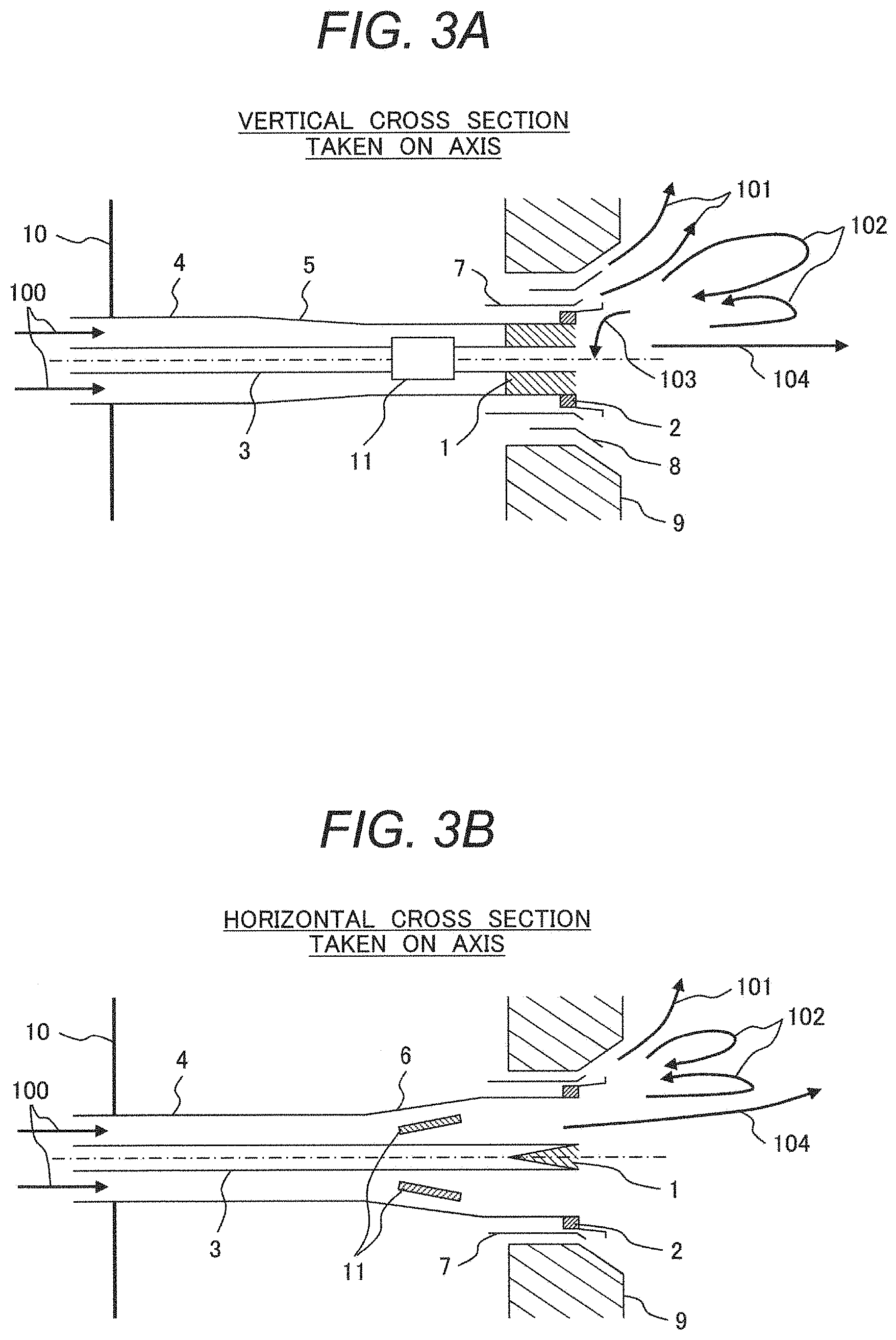
[0080] FIG. 3A is an illustrative diagram showing a vertical cross section of a solid fuel burner according to Example 3 hereof as taken on the axis thereof. FIG. 3B is an illustrative diagram showing a horizontal cross section of the solid fuel burner according to Example 3 hereof as taken on the axis thereof.
[0081] In addition to the solid fuel burner of Example 2, the solid fuel burner according to the example further includes a horizontal vane 11 which is disposed in the diffusion portion 6 and adapted to throw the particles horizontally outward. Namely, the solid fuel burner of this example includes the horizontal vane 11 which is disposed in the diffusion portion 6 so as to disperse the mixing gas 100 horizontally outward.
[0082] The solid fuel burner according to the example is decreased in the fuel (particles) density in the vicinity of the outer peripheral flame stabilizer 2 because the particle concentrator is omitted. The large recirculation flow 102 is formed with respect to the vertical parts of the outer peripheral flame stabilizer 2 and hence, the particles are captured by the large recirculation flow 102 despite the decreased fuel (particles) density. Thus, the ignition and flame holding are ensured. However, the recirculation flow 102 is relatively small with respect to the horizontal parts of the outer peripheral flame stabilizer 2 so that the outer peripheral stabilizer may be less likely to achieve ignition and flame holding.
[0083] The solid fuel burner of the example is provided with the horizontal vane 11 for particle concentration on the horizontally outer side so as to concentrate the particles to the vicinity of the horizontal parts of the outer peripheral flame stabilizer 2 and to facilitate the horizontally outer peripheral flame holding.
[0084] The solid fuel burner of the example is adapted to control the fuel (particles) density in the vicinity of the inner flame stabilizer 1 and the fuel (particles) density in the vicinity of the horizontal parts of the outer peripheral flame stabilizer 2 by changing the installation angle of the horizontal vane 11. Thus, the burner can adjust the combustion state. By virtue of the movable structure of the horizontal vane 11, the solid fuel burner can properly control the combustion state according to the operating conditions.
Fourth Embodiment
[0085] FIG. 4A is an illustrative diagram showing a vertical cross section of a solid fuel burner according to Example 4 hereof as taken on the axis thereof. FIG. 4B is an illustrative diagram showing a horizontal cross section of the solid fuel burner according to Example 4 hereof as taken on the axis thereof.
[0086] In addition to the solid fuel burner of Example 2, the solid fuel burner according to the example further includes a swirling vane 12 which stirs the particles as disposed on an upstream side of the throttling portion 5. Namely, the solid fuel burner of the example includes the swirling vane 12 disposed in the straight tube portion 4 so as to stir the mixing gas 100.
[0087] The mixing gas 100 flows through a long pipe (not shown) to be supplied to the straight tube portion 4. In this process, the mixing gas passes many bending portions where only the particles are centrifugally shifted to the outer side so that the density deviation of the fuel (particles) occurs in the pipe. This density deviation of the fuel (particles) may sometimes cause particle aggregation at some unanticipated place (straight tube portion 4) upstream of the throttling portion 5, which may interfere with ignition or flame holding in the inner flame stabilizer and the outer peripheral flame stabilizer 2.
[0088] In the solid fuel burner of the example, therefore, the swirling vane 12 for stirring the particles is disposed at place (straight tube portion 4) upstream of the throttling portion 5 so as to control the density deviation of the fuel (particles) flowing through the throttling portion 5 and to facilitate the ignition and flame holding in the inner flame stabilizer 1 or the outer peripheral flame stabilizer 2.
[0089] While the example employs the swirling vane 12 as the particle stirring structure, the stirring structure may have another configuration such as a turning blade (a component such as a conical structure for diffusing the mixing gas 100 toward the outer periphery).
Fifth Embodiment
[0090] FIG. 5A is an illustrative diagram showing a vertical cross section of a solid fuel burner according to Example 5 hereof as taken on the axis thereof. FIG. 5B is an illustrative diagram showing a horizontal cross section of the solid fuel burner according to Example 5 hereof as taken on the axis thereof.
[0091] In addition to the solid fuel burner of Example 2, the solid fuel burner according to the example further includes a pipe which is disposed on an upstream side of the straight tube portion 4 and includes a bending portion 13 connected to the straight tube portion 4 (the bending portion according to the example is a planar member which can be opened and closed for maintenance work). The bending portion 13 of the pipe is provided with a guide (guide plate) 14 for dividing the flow passage into an inner side and an outer side with respect to the bending portion 13. Namely, the solid fuel burner includes, on the upstream side of the straight tube portion 4, the pipe including the bending portion 13 connected to the straight tube portion 4, and the guide (guide plate) 14 disposed at the bending portion 13 of the pipe for centrifugally dividing the mixing gas 100.
[0092] When flowing through the bending portion 13, the mixing gas 100 allows only the particles to be centrifugally shifted toward the outer side. Disposing the guide (guide plate) 14 restricts the particles from being shifted only toward the outer side with respect to the bending portion 13. Thus, the burner can provide vertically well-balanced supply of particles.
[0093] This configuration obviates the extreme density deviation of the fuel (particles) in the outlet portion 16, facilitating the ignition and flame holding in the inner flame stabilizer 1 and the outer peripheral flame stabilizer 2.
[0094] A structure such as the guide (guide plate) 14 disposed in the bending portion 13 of the pipe dispenses with the need for disposing the structure such as the swirling vane 12 in the straight tube portion 4. Hence, the solid fuel burner can be reduced in the axial length. This leads to reduction of production cost of the burner.
Sixth Embodiment
[0095] FIG. 6A is an illustrative diagram showing a vertical cross section of a solid fuel burner according to Example 6 hereof as taken on the axis thereof. FIG. 6B is an illustrative diagram showing a horizontal cross section of the solid fuel burner according to Example 6 hereof as taken on the axis thereof.
[0096] In addition to the solid fuel burner of Example 3, the solid fuel burner according to the example further includes a pipe which is disposed on an upstream side of the straight tube portion 4 and includes a bending portion 13 connected to the straight tube portion 4 (the bending portion according to the example is a planar member which can be opened and closed for maintenance work).
[0097] A particle dispersion plate 15 for dispersing the particles is disposed at an outlet of the bending portion 13. That is, the straight tube portion 4 includes the particle dispersion plate 15 for dispersing the mixing gas 100.
[0098] The particle dispersion plate 15 is disposed only on a centrifugally outer side of the bending portion 13. This is for the purpose of utilizing the particle dispersion plate 15 to effectively disperse the centrifugally outwardly shifted particles because the particles are shifted to the centrifugally outer side of the bending portion 13. By disposing the particle dispersion plate 15 only on the centrifugally outer side, the reduction of the cross-sectional area of the flow passage in the straight tube portion 4 can be obviated so that the increase in particle velocity in the straight tube portion 4 is also limited. Accordingly, the wear volume of the inner wall of the fuel nozzle is also reduced.
[0099] The particle dispersion plate 15 provides a balanced flow of the particles through the fuel nozzle so as to permit the horizontal vane 11 on a downstream from the particle dispersion plate 15 to achieve an efficient particle distribution. Thus, the burner can control the combustion state.
Seventh Embodiment
[0100] FIGS. 7A to 7F illustrate the detailed structures of the inner flame stabilizers 1 in FIGS. 1A to 6B.
[0101] FIG. 7A illustrates the basic structure of the inner flame stabilizers of the burners exemplified in FIGS. 1A to 6B respectively, which structure takes a wedge structure of triangular prism. FIGS. 7B to 7F illustrate modifications of the structure of the inner flame stabilizer in FIG. 7A.
[0102] The structure in FIG. 7B is provided with a recess portion 105 on the backside of the inner flame stabilizer on the downstream side of the fuel jet flow 104 in terms of the basic structure thereof shown in FIG. 7A. The provision of such recess portion 105 on the backside of the inner flame stabilizer promotes the mixing of the high-temperature gas flow 103 and the fuel jet flow 104, thereby, further facilitating ignition compared to such basic structure.
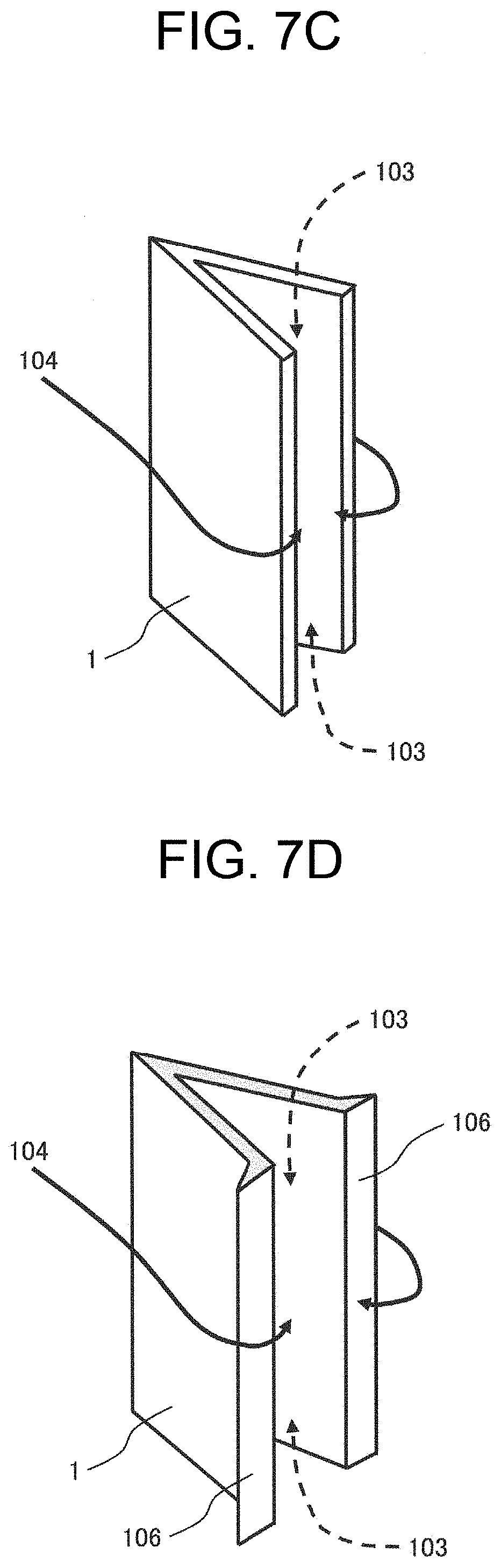
[0103] As to the structure in FIG. 7C-1, making the inner flame stabilizer, in which a plate is arranged such that it has a V-shape structure, take a V-shape structure without providing such stabilizer with a backside as shown in FIG. 7A promotes the mixing of the high-temperature gas flow 103 and the fuel jet flow 104 and leads to cost reduction by reducing the number of the parts of such stabilizer in the same way as the recess portion 105 in FIG. 7B.
[0104] As to the structure in FIG. 7C-2, an baffle plate 106 is disposed at the tip end of the V-shape structure in FIG. 7C-1. Providing the tip end of the plate member taking a V-shape structure with such baffle plate 106 so as to enlarge the cross-sectional area of the tip end of the plate taking such V-shape structure further promotes the mixing of the fuel jet flow 104 and the high-temperature gas flow 103 than the structure in FIG. 7C-1, thereby, facilitating ignition.
[0105] In FIG. 7D, the horizontal cross-section of the inner flame stabilizer has a pentagonal prism structure. The inner flame stabilizer in FIG. 7D has a larger volume than the counterpart whose horizontal cross section takes a triangular prism defining isosceles triangle and is excellent in anti-abrasion property as well as is inexpensively producible without use of expensive ceramic materials. In addition, since such stabilizer is excellent in anti-abrasion property, it is applicable to the combustion of the low-grade coal whose ash content is higher.
[0106] FIG. 7E illustrates the structure of the recess portion 105 in FIG. 7B with the exclusion of the vertical notch. In other words, FIG. 7B corresponds to the structure with the inclusion of the vertical notch in the recess portion in FIG. 7E. Comparing this structure with that in FIG. 7B, high negative pressure created by the recess portion 105 further promotes the mixing of the high-temperature gas flow 103 and the fuel jet flow 104, thereby, leading to excellent ignition property. This structure is also effective for the stable ignition of the start-up oil burner which requires higher negative pressure in the same way as coal.
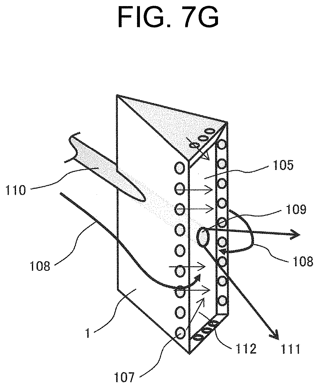
[0107] The structure in FIG. 7F is provided with the inner flame stabilizer 1, the recess portion 105 and air inlets 107 which supply air into the recess portion 105. The air inlets 107 are provided on the outer periphery of the recess portion. In FIG. 7F, in order to explain the function of the recess portion 105 and the ignition promotion of the start-up oil burner, a start-up oil burner tip 109 and a start-up oil burner gun 110 are also illustrated.
[0108] Oil fuel 111 is jet-sprayed from the start-up oil burner tip 109 toward the furnace so as to turn into flame. Upon the start-up, the solid fuel is not supplied, but a combustion fuel flow and/or an air flow 108 is fed and a part of such flow flows from the air inlets 107 into the periphery of the start-up oil burner tip 109 to generate an air flow 112 toward the recess portion.
[0109] Further, since high negative pressure is created by the recess portion 105, the high-temperature gas flow 103 and the fuel jet flow 104 flow into the recess portion 105. Accordingly, the air flow 112 into the recess portion promotes the ignition of the oil fuel and reduces soot and dust as well as suppresses the coking (carbonization) of the start-up oil burner tip 109.
[0110] To note, as to the air inlets 107, because of a small amount of air intake structure, they are not limited to the pore structure and may be arranged with another structure such as slit. Further, in FIG. 7F, a plurality of the air inlets 107 are provided over the entire periphery of the recess portion 105, but they may be provided on any one of the sides constituting the recess portion and the number of such inlets may be one or more. Moreover, when the air inlets are made not of pores but of slits, such slits may be provided over the entire periphery and the number of such slits and their length may be set in an arbitrary manner.
[0111] To note, the start-up oil burner tip 109 and the start-up oil burner gun 110 are shown only in FIG. 7F according to the present example, but such start-up oil burner tip is provided for the inner flame stabilizers in FIGS. 7A to 7E as well such that such tip penetrates such stabilizers, thereby, enabling the stable combustion upon the solid fuel combustion and the oil combustion.
[0112] It is noted that the present invention is not limited to the above-described examples and includes a variety of modifications. The foregoing examples, for example, are the detailed illustrations to clarify the present invention. The present invention is not necessarily limited to those including all the components described above. Some component of one example can be replaced by some component of another example. Further, some configuration of one example can be added to the configuration of another example.
LIST OF REFERENCE SIGNS
[0113] 1: inner flame stabilizer [0114] 2: outer peripheral flame stabilizer [0115] 3: central supporting rod [0116] 4: fuel nozzle straight tube portion [0117] 5: fuel nozzle throttling portion [0118] 6: fuel nozzle diffusion portion [0119] 7: guide sleeve [0120] 8: guide sleeve [0121] 9: furnace wall [0122] 10: wind box [0123] 11: horizontal vane [0124] 12: swirling vane [0125] 13: bending portion [0126] 14: guide [0127] 15: particle dispersion plate [0128] 16: fuel nozzle outlet portion [0129] 100: mixing gas [0130] 101: combustion air jet flow [0131] 102: recirculation flow [0132] 103: high-temperature flow [0133] 104: fuel jet flow [0134] 105: recess portion [0135] 106: baffle plate [0136] 107: air inlet [0137] 108: solid fuel flow and/or air flow [0138] 109: start-up oil burner tip [0139] 110: start-up oil burner gun [0140] 111: oil fuel [0141] 112: air flow toward recess portion
* * * * *
D00000
D00001
D00002
D00003
D00004
D00005
D00006
D00007
D00008
D00009
D00010
XML
uspto.report is an independent third-party trademark research tool that is not affiliated, endorsed, or sponsored by the United States Patent and Trademark Office (USPTO) or any other governmental organization. The information provided by uspto.report is based on publicly available data at the time of writing and is intended for informational purposes only.
While we strive to provide accurate and up-to-date information, we do not guarantee the accuracy, completeness, reliability, or suitability of the information displayed on this site. The use of this site is at your own risk. Any reliance you place on such information is therefore strictly at your own risk.
All official trademark data, including owner information, should be verified by visiting the official USPTO website at www.uspto.gov. This site is not intended to replace professional legal advice and should not be used as a substitute for consulting with a legal professional who is knowledgeable about trademark law.