Environmental Barrier Coating For Enhanced Resistance To Attack By Molten Silicate Deposits
Zaleski; Elisa M. ; et al.
U.S. patent application number 15/998731 was filed with the patent office on 2020-02-20 for environmental barrier coating for enhanced resistance to attack by molten silicate deposits. This patent application is currently assigned to United Technologies Corporation. The applicant listed for this patent is United Technologies Corporation. Invention is credited to Richard Wesley Jackson, Xia Tang, Elisa M. Zaleski.
| Application Number | 20200056489 15/998731 |
| Document ID | / |
| Family ID | 67659116 |
| Filed Date | 2020-02-20 |

| United States Patent Application | 20200056489 |
| Kind Code | A1 |
| Zaleski; Elisa M. ; et al. | February 20, 2020 |
ENVIRONMENTAL BARRIER COATING FOR ENHANCED RESISTANCE TO ATTACK BY MOLTEN SILICATE DEPOSITS
Abstract
An environmental barrier coating, comprising a substrate containing silicon; an environmental barrier layer applied to said substrate; said environmental barrier layer comprising a rare earth composition.
| Inventors: | Zaleski; Elisa M.; (Manchester, CT) ; Jackson; Richard Wesley; (Groton, CT) ; Tang; Xia; (West Hartford, CT) | ||||||||||
| Applicant: |
|
||||||||||
|---|---|---|---|---|---|---|---|---|---|---|---|
| Assignee: | United Technologies
Corporation Farmington CT |
||||||||||
| Family ID: | 67659116 | ||||||||||
| Appl. No.: | 15/998731 | ||||||||||
| Filed: | August 16, 2018 |
| Current U.S. Class: | 1/1 |
| Current CPC Class: | C04B 41/5024 20130101; C23C 26/00 20130101; C04B 41/89 20130101; F23R 3/007 20130101; F23R 2900/00018 20130101; C04B 41/87 20130101; F01D 5/288 20130101; F05D 2240/30 20130101; F05D 2300/6033 20130101; C04B 41/009 20130101; F05D 2300/222 20130101; C04B 41/85 20130101; C04B 41/52 20130101; F05D 2240/12 20130101; F05D 2300/611 20130101; C04B 41/5015 20130101; F05D 2220/32 20130101; F05D 2300/211 20130101; F05D 2300/2108 20130101; C23C 4/134 20160101; C04B 41/009 20130101; C04B 35/565 20130101; C04B 35/806 20130101; C04B 41/5024 20130101; C04B 41/5048 20130101; C04B 2103/001 20130101; C04B 2103/0021 20130101; C04B 41/52 20130101; C04B 41/5024 20130101; C04B 2103/0021 20130101; C04B 41/52 20130101; C04B 41/5024 20130101; C04B 41/52 20130101; C04B 41/5042 20130101; C04B 41/522 20130101 |
| International Class: | F01D 5/28 20060101 F01D005/28; C04B 41/00 20060101 C04B041/00; C04B 41/50 20060101 C04B041/50; C04B 41/85 20060101 C04B041/85 |
Claims
1. An environmental barrier coating, comprising: a substrate containing silicon; an environmental barrier layer applied to said substrate; said environmental barrier layer comprising a rare earth composition.
2. The environmental barrier coating of claim 1, wherein said substrate comprises a ceramic matrix composite material.
3. The environmental barrier coating of claim 1, wherein said environmental barrier layer comprises a rare earth apatite.
4. The environmental barrier coating of claim 1, wherein said environmental barrier layer comprises RE.sub.8Ca.sub.2(SiO.sub.4).sub.6O.sub.2.
5. The environmental barrier coating of claim 1, wherein said environmental barrier layer comprises an apatite comprising Ca.sub.5F(PO.sub.4).sub.3.
6. The environmental barrier coating of claim 5, wherein said Ca can be substituted with Mg, Fe, Na, Sr, and Mn.
7. The environmental barrier coating of claim 1, wherein said substrate comprises at least one of a turbine vane and a turbine blade.
8. The environmental barrier coating of claim 1, further comprising: a protective layer applied on said environmental barrier coating.
9. The environmental barrier coating of claim 1, wherein said environmental barrier layer comprises an apatite comprising M.sup.I.sub.4M.sup.II.sub.6(SiO.sub.4).sub.6X.sub.2 in which M.sup.I are seven-fold coordinated cation sites and M.sup.II are nine-fold coordinated cation sites, and X is an anion sites that is distinct from the oxygen within the silica tetrahedral.
10. The environmental barrier coating of claim 9, wherein RE ions sit on both the M.sup.I and M.sup.II sites and Ca sits on the M.sup.I site fitting the formula RE.sub.8Ca.sub.2(SiO.sub.4).sub.6O.sub.2.
11. The environmental barrier coating of claim 9 wherein said apatite further comprises Mg and Fe additions.
12. The environmental barrier coating of claim 11 wherein said apatite comprises Ca.sub.2-x-yMg.sub.xFe.sub.y where 0>x>1 and 0>y>1.
13. The environmental barrier coating of claim 9 wherein at least one of Ca, Mg, Fe, Sr, Na, K, Ti, and Zr is combined with the rare earth composition.
Description
BACKGROUND
[0001] The disclosure relates to an article comprising a substrate containing silicon and an environmental barrier coating (EBC) which functions as a protective environmental barrier coating and inhibits the formation of gaseous species of Si, particularly Si(OH).sub.x when the article is exposed to a high temperature, aqueous (steam) environment.
[0002] Ceramic materials containing silicon and metal alloys containing silicon have been proposed for structures used in high temperature applications as, for example, gas turbine engines, heat exchangers, internal combustion engines, and the like. A particular useful application for these materials is for use in gas turbine engines which operate at high temperatures in steam-laden environments.
[0003] It has been found that these silicon containing structures can recess and lose mass as a result of formation of volatile silicon species, particularly Si(OH).sub.x and SiO when exposed to high temperature, steam-laden environments.
[0004] It is believed that the process involves oxidation of the silicon containing structure to form silica on the surface followed by reaction of the silica with steam to form volatile species of silicon such as Si(OH).sub.x. Naturally it would be highly desirable to provide an external barrier coating for silicon containing substrates which would inhibit the formation of volatile silicon species, Si(OH).sub.x and SiO, and thereby reduce recession and mass loss.
SUMMARY
[0005] In accordance with the present disclosure, there is provided an environmental barrier coating, comprising a substrate containing silicon; an environmental barrier layer applied to the substrate; the environmental barrier layer comprising a rare earth composition.
[0006] In another and alternative embodiment, the substrate comprises a ceramic matrix composite material.
[0007] In another and alternative embodiment, the environmental barrier layer comprises a rare earth apatite.
[0008] In another and alternative embodiment, the environmental barrier layer comprises RE.sub.8Ca.sub.2(SiO.sub.4).sup.6O.sub.2.
[0009] In another and alternative embodiment, the environmental barrier layer comprises an apatite comprising Ca.sub.5F(PO.sub.4).sub.3.
[0010] In another and alternative embodiment, the Ca can be substituted with Mg, Fe, Na, Sr, and Mn.
[0011] In another and alternative embodiment, the substrate comprises at least one of a turbine vane and a turbine blade.
[0012] In another and alternative embodiment, the environmental barrier coating further comprises a protective layer applied on the environmental barrier coating.
[0013] In another and alternative embodiment, the environmental barrier layer comprises an apatite comprising M.sup.I.sub.4M.sup.II.sub.6(SiO.sub.4).sub.6X.sub.2 in which M.sup.I are seven-fold coordinated cation sites and M.sup.II are nine-fold coordinated cation sites, and X is an anion sites that is distinct from the oxygen within the silica tetrahedral.
[0014] In another and alternative embodiment, the RE ions sit on both the M.sup.I and M.sup.II sites and Ca sits on the M.sup.I site fitting the formula RE.sub.8Ca.sub.2(SiO.sub.4).sub.6O.sub.2.
[0015] In another and alternative embodiment, the apatite further comprises Mg and Fe additions.
[0016] In another and alternative embodiment, the apatite comprises Ca.sub.2-x-yMg.sub.xFe.sub.y where 0>x>1 and 0>y>1.
[0017] In another and alternative embodiment, at least one of Ca, Mg, Fe, Sr, Na, K, Ti, and Zr is combined with the rare earth composition.
[0018] Other details of the coating are set forth in the following detailed description and the accompanying drawings wherein like reference numerals depict like elements.
BRIEF DESCRIPTION OF THE DRAWINGS
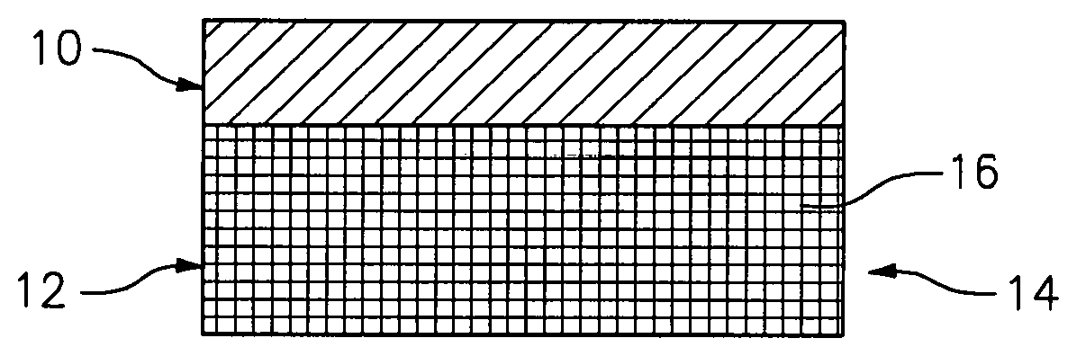
[0019] FIG. 1 is a cross section of an exemplary coating on a substrate containing silicon according to the disclosure.
[0020] FIG. 2 is a cross section of an exemplary coating on a substrate containing silicon according to the disclosure.
DETAILED DESCRIPTION
[0021] Referring now to FIG. 1, there is illustrated an environmental barrier coating 10 formed over a substrate 12 of an article 14, configured to inhibit the formation of gaseous species of silicon when the article 14 is exposed to a high temperature, aqueous environment. The substrate 12 can be associated with articles 14 such as, at least one of a turbine vane and a turbine blade, and particularly a gas turbine engine component, such as components in the hot section of the gas turbine engine, including static and rotating components and portions of combustors, and the like.
[0022] The substrate 12 can be constructed from materials containing silicon and can be a ceramic matrix composite material, a monolithic ceramic, a silicon-based or silicon containing ceramic substrate or a silicon containing metal alloy. In an exemplary embodiment, the substrata 12 can be silicon containing ceramic material such as, for example, silicon carbide, silicon nitride, silicon oxy-nitride and silicon aluminum oxy-nitride, alkaline earth or rare earth silicate glasses or glass ceramics and combinations thereof. Examples can include barium strontium alumino silicate, strontium alumino silicate, lithium alumino silicate, aluminosilicate, mullite, yttrium silicate, ytterbium silicate, and the like. In accordance with a particular embodiment, the silicon containing ceramic substrate comprises a silicon containing matrix with reinforcing materials 16 such as fibers, particles and the like and, more particularly, a silicon based matrix which is fiber-reinforced. Particularly suitable ceramic substrates are a silicon carbide fiber-reinforced silicon carbide matrix, a carbon fiber-reinforced silicon carbide matrix and a silicon carbide fiber-reinforced silicon nitride matrix. Particularly useful silicon-metal alloys for use as substrates for the article 14 can include molybdenum-silicon alloys, niobium-silicon alloys, iron-silicon alloys, zirconium, hafnium, titanium, chromium, tungsten, boron, platinum, tantalum, Ti--Si alloys and Mo--Si, Nb--Si and Fe--Si alloys.
[0023] Referring also to FIG. 2, an environmental barrier layer 18 can be applied to the substrate 12 on a surface 20. A protective layer 22 can be applied on the environmental barrier layer 18. The protective layer 22 is configured to resist recession of the Si-containing volatile species when exposed to water vapor or steam. In an exemplary embodiment, the protective layer 22 can include binary or multicomponent oxides such as HfO.sub.2, ZrO.sub.2, or Gd.sub.2Hf.sub.2O.sub.7, Gd.sub.2Zr.sub.2O.sub.7, refractory metal oxides. In other exemplary embodiments, the protective layer 22 can include silicates with low(er) SiO.sub.2 activities. In another exemplary embodiment the protective layer 22 can include (rare earth) RE-monosilicates, disilicates and (alkaline earth) AE alumino silicates, silicates of Hafnium and zirconium.
[0024] The environmental barrier layer 18 can include a rare earth (RE) composition, such as rare earth apatites. In an exemplary embodiment the apatite can comprise M.sup.I.sub.4M.sup.II.sub.6(SiO.sub.4).sub.6X.sub.2 in which M.sup.I are seven-fold coordinated cation sites and M.sup.II are nine-fold coordinated cation sites, and X is an anion sites that is distinct from the oxygen within the silica tetrahedral. In another exemplary embodiment RE ions sit on both the M.sup.I and M.sup.II sites while Ca sits on the M.sup.I site fitting the formula RE.sub.8Ca.sub.2(SiO.sub.4).sub.6O.sub.2. Alternatively, the composition may be modified by Mg and Fe additions, to include Ca.sub.2-x-yMg.sub.xFe.sub.y where 0>x>1 and 0>y>1. Such that in the RE.sub.8(Ca.sub.2-x-yMg.sub.xFe.sub.y)(SiO.sub.4).sub.6O.sub.2, the Ca, Mg, Fe composition is chosen to maximize chemical stability with the deposits in which the primary chemical specials are Ca--Mg--Fe--Al--Si--O. Alternatively, elements such as Ca, Mg, Fe, Sr, Na, K, Ti, and Zr may be added with the rare earth elements. Particularly, the environmental barrier layer 18 can include RE.sub.8Ca.sub.2(SiO.sub.4).sub.6O.sub.2. In another exemplary embodiment the environmental barrier layer 18 can include an apatite comprising Ca.sub.5F(PO.sub.4).sub.3. The Ca can be substituted with Mg, Fe, Na, Sr, and Mn. These substitutions can occur in the RE.sub.8Ca.sub.2 (SiO.sub.4).sub.6O.sub.2 apatite.
[0025] The environmental barrier layer 18 can be present on the substrate 12 at a thickness of greater than or equal to about 0.5 mils (0.0005 inch), preferably between about 3 to about 30 mils and ideally between about 3 to about 5 mils.
[0026] The environmental barrier layer 18 can be applied by preparing a surface 20 of the substrate 14. The environmental barrier layer 18 can be applied to the substrate 12 by use of suspension plasma spray, electron-beam physical vapor deposition, or an air plasma spray, as well as, slurry based method including dipping, painting and spraying.
[0027] In an alternative embodiment, the environmental barrier coating 10 can be formed as multiple combinations of layers 18. In another alternative embodiment, the environmental barrier layer 18 can be multiple layers 24 of RE based on varying RE concentration. In another alternative embodiment, the environmental barrier coating 10 can be multiple layers of RE based on varying the deposition technique, resulting a varying material properties by layer(s). In an exemplary embodiment the environmental barrier layer 18 can include multiple layers 24 applied by applying a suspension plasma spray layer and then an air plasma spray layer.
[0028] In an exemplary embodiment, a bond layer can be added in between the environmental barrier layer 18 and the substrate 12 on top of surface 20 for adhesion and oxidation protection.
[0029] An advantage of utilizing the disclosed environmental barrier coating 10 composition that is near equilibrium with the silicate melt can include limited mixing of the silicate melt and the environmental barrier coating 10, thus reducing swelling and phase change in the coating. Another advantage of utilizing the disclosed environmental barrier coating 10 composition that is near equilibrium with the silicate melt can include a limited chemical reaction between the environmental barrier coating 10 and the silicate melt that can result in limited new phase formation. This limitation can decrease the strain induced in the top layer of the coating 10 as a result of a mismatch of coefficient of thermal expansion between the reaction products, thus increasing the life of the coating 10.
[0030] There has been provided a coating. While the coating has been described in the context of specific embodiments thereof, other unforeseen alternatives, modifications, and variations may become apparent to those skilled in the art having read the foregoing description. Accordingly, it is intended to embrace those alternatives, modifications, and variations which tall within the broad scope of the appended claims.
* * * * *
D00000
D00001
XML
uspto.report is an independent third-party trademark research tool that is not affiliated, endorsed, or sponsored by the United States Patent and Trademark Office (USPTO) or any other governmental organization. The information provided by uspto.report is based on publicly available data at the time of writing and is intended for informational purposes only.
While we strive to provide accurate and up-to-date information, we do not guarantee the accuracy, completeness, reliability, or suitability of the information displayed on this site. The use of this site is at your own risk. Any reliance you place on such information is therefore strictly at your own risk.
All official trademark data, including owner information, should be verified by visiting the official USPTO website at www.uspto.gov. This site is not intended to replace professional legal advice and should not be used as a substitute for consulting with a legal professional who is knowledgeable about trademark law.