Scaffold Planks
Curtis; Johnny ; et al.
U.S. patent application number 16/663529 was filed with the patent office on 2020-02-20 for scaffold planks. The applicant listed for this patent is Next Generation Scaffold Services, Inc.. Invention is credited to Johnny Curtis, Stephen Howard Thacker.
| Application Number | 20200056384 16/663529 |
| Document ID | / |
| Family ID | 63920132 |
| Filed Date | 2020-02-20 |


View All Diagrams
| United States Patent Application | 20200056384 |
| Kind Code | A1 |
| Curtis; Johnny ; et al. | February 20, 2020 |
Scaffold Planks
Abstract
A first scaffold plank member having a board like member having a top surface, first and second opposing end edges and a first and second opposing side edges; a first and second side rails, the side rail attached to the board like member near the respective side edges, each respective side rail extending downwardly from the top surface, each side rail having an inward and an outward facing surface, positioned near both the first and second opposing end edges, a first and second clips separated by a distance from one another, the first and second clips extending outwardly from the respective end edges, each clip having a terminating downwardly projecting lip, and a channel section located between the lip and the respective end edge, the channel section shaped to engage a horizontal scaffold member; a series of slots through the top surface, said series of slots positioned near the first side edge, each slot of said series of slots having a portion of the slot positioned inwardly of the inward facing surface, each slot being sized to accept a portion of a clip through the slot, two of said slots are separated a distance to accept two clips on a second scaffold board whereby, if a portion of a second scaffold plank's first and second clips are inserted through these slots, so that the second scaffold plank is supported by the first scaffold plank.
| Inventors: | Curtis; Johnny; (Denham Springs, LA) ; Thacker; Stephen Howard; (The Woodlands, TX) | ||||||||||
| Applicant: |
|
||||||||||
|---|---|---|---|---|---|---|---|---|---|---|---|
| Family ID: | 63920132 | ||||||||||
| Appl. No.: | 16/663529 | ||||||||||
| Filed: | October 25, 2019 |
Related U.S. Patent Documents
| Application Number | Filing Date | Patent Number | ||
|---|---|---|---|---|
| PCT/US18/29615 | Apr 26, 2018 | |||
| 16663529 | ||||
| 62490908 | Apr 27, 2017 | |||
| Current U.S. Class: | 1/1 |
| Current CPC Class: | E04G 5/08 20130101; E04G 1/152 20130101; E04G 7/00 20130101 |
| International Class: | E04G 5/08 20060101 E04G005/08; E04G 7/00 20060101 E04G007/00 |
Claims
1. A first scaffold plank member comprising a board like member having a top surface, first and second opposing end edges and a first and second opposing side edges; a first and second side rails, said first side rail attached to the board like member near the first side edge, and the second side rail attached near said second side edge, each respective side rail extending downwardly from the top surface, each side rail having at least one outward facing surface and at least one inward facing surface; positioned near both the first and second opposing end edges, a first and second clip attached to the first scaffold plank separated by a distance from one another, the first and second clips extending outwardly from the respective end edges, each clip having a terminating downwardly projecting lip, and a channel section located between the lip and the respective end edge, the channel section shaped to engage a horizontal scaffold member; a series of slots through the top surface, said series of slots positioned near the first side edge, each slot of said series of slots having a portion of the slot positioned inwardly of one of said at least one inward facing surfaces of said first side rail, each slot in said series of slots being sized to accept a portion of a clip through said slot, each slot of said series of slots positioned through said top surface of said first scaffold plank and at least two of said slots in said series of slots are separated a distance to accept two clips on a second scaffold board whereby, if a portion of a second scaffold plank's first and second clips on said first end edge of said second scaffold plank edge are inserted through two of said slots in said series of slots, the lips of such inserted first and second clips would be positioned near to one of said at least one inward facing surfaces of said first side rail of said first scaffold plank and the channels of the second scaffold plank are thereby supported by the first scaffold plank, the top surfaces of said first and second scaffold board's top surfaces are closely aligned, and the first end edge of the second scaffold board is solely supported by said first scaffold plank.
2. The first scaffold plank of claim 1 where each of said series of slots are aligned with one another on an axis on said top surface extending between said first and second end edges.
3. The first scaffold plank of claim 1 where each of said series of slots begin at said first side edge and extend toward said second side edge.
4. The first scaffold plank of claim 3 wherein each of said series of slots are positioned partially through said first side rail.
5. The first scaffold plank of claim 4 wherein each of said slots in series of slots has a bottom portion that terminates in said first side rail, said bottom forming a landing site to couple to a clip on a second scaffold board inserted into one of said slots to thereby support a second scaffold board on said bottom portion.
6. The first scaffold plank of claim 2 wherein said slots are offset a distance from said first edge, and said top of said scaffold board between each slot and said first edge form landing sites to couple to a clip on a second scaffold board inserted into one of said slots to thereby support a second scaffold board on said landing site.
7. The first scaffold plank of claim 3 where said series of slots are not equally spaced along said first edge.
8. The first scaffold board according to claim 4 wherein the clip width above said channel, said width being less than or equal to the depth of the slot bottom from the top surface.
9. A method of coupling a first scaffold plank with a second scaffold plank on at least one end, in a scaffold structure comprising horizontal and vertical scaffold members; the first scaffold plank comprising a board like member having a top surface, a bottom surface, first and second terminating ends each with an end edge, and a first and second opposing side edges; a first and second side rails, said first side rail attached to the board like member near the first side edge, and the second side rail attached near said second side edge, each respective side rail extending downwardly from the top surface, each side rail having at least one outward facing surface and at least one inward facing surface; positioned near both the first and second opposing end edges, a first and second clip attached to the first scaffold plank separated by a distance from one another, the first and second clips extending outwardly from the respective end edges, each clip having a terminating downwardly projecting lip, and a channel section located between the lip and the respective end edge, the channel section shaped to engage a horizontal scaffold member; a series of slots through the top surface, said series of slots positioned near the first side edge, each slot of said series of slots having a portion of the slot positioned inwardly of one of said at least one inward facing surfaces of said first side rail, each slot in said series of slots being sized to accept a portion of a clip through said slot, each slot of said series of slots positioned through said top surface of said first scaffold plank and at least two of said slots in said series of slots are separated a distance to accept two clips on a second scaffold board; said first scaffold board supported by a first and second horizontal member on its two terminating end edges; said second scaffold board comprising: a board like member having a top surface, a bottom surface, first and second terminating ends each with an end edge, and a first and second opposing side edges; a first and second side rails, said first side rail attached to the board like member near the first side edge, and the second side rail attached near said second side edge, each respective side rail extending downwardly from the top surface, each side rail having at least one outward facing surface and at least one inward facing surface; positioned near both the first and second opposing end edges, a first and second clip attached to the first scaffold board separated by a distance from one another, the first and second clips extending outwardly from the respective end edges, each clip having a terminating downwardly projecting lip, and a channel section located between the lip and the respective end edge, the channel section shaped to engage a horizontal scaffold member the method comprising the steps of: positioning said second scaffold board at substantially 90 degrees to said first scaffold board, said second scaffold board positioned such that the first and second clips of the second scaffold board on the first terminating end are aligned with corresponding slots on the first scaffold board; lowering the second scaffold board's first terminating end so that a portion of the first and second clips on the second scaffold board member pass through the aligned slots of the first scaffold board until the second scaffold board's first terminating end is supported solely by the first scaffold board member without said second scaffold board's first terminating end being directly coupled to a horizontal scaffold member.
10. The method of claim 9 where said first scaffold plank further comprises where each of said series of slots are aligned with one another on an axis on said top surface extending between said first and second end edges.
11. The method of claim 9 where said first scaffold plank further comprises where each of said series of slots begin at said first side edge and extend toward said second side edge.
12. The method of claim 11 where said first scaffold plank further comprises wherein each of said series of slots are positioned partially through said first side rail.
13. The method of claim 12 where said first scaffold plank further comprises: wherein each of said slots in series of slots has a bottom portion that terminates in said first side rail, said bottom forming a landing site to couple to a clip on a second scaffold board inserted into one of said slots to thereby support a second scaffold board on said bottom portion.
14. The method of claim 10 where said first scaffold plank further comprises wherein said slots are offset a distance from said first edge, and said top of said scaffold board between each slot and said first edge form landing sites to couple to a clip on a second scaffold board inserted into one of said slots to thereby support a second scaffold board on said landing site.
15. The method of claim 11 where said first scaffold plank further comprises where said series of slots are not equally spaced along said first edge.
16. The method of claim 12 where said first scaffold plank further comprises the first scaffold board according to claim 4 wherein the clip width above said channel, said width being less than or equal to the depth of the slot bottom from the top surface.
Description
CROSS-REFERENCE TO RELATED APPLICATION
[0001] This application is a continuation of PCT/US2018/29615 filed on Apr. 26, 2018, which application claimed the priority benefit of U.S. Provisional Application 62/490,908 filed Apr. 27, 2017, both of which are incorporated by reference herein in their entirety.
BACKGROUND
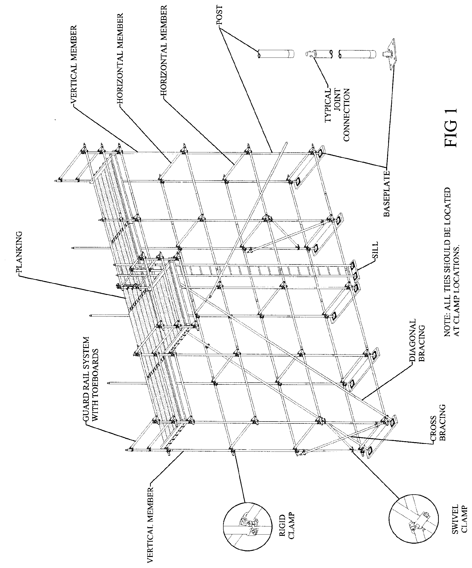
[0002] A scaffold frame is an interconnected series of horizontal vertical scaffold members and vertical scaffold members used to create a supporting structure for an elevated work surface. The horizontal and vertical scaffold members are generally pipe shaped members (circular or square in cross section, for instance) where the ends of each horizontal scaffold member terminates in connectors that attaches to a vertical scaffold members. The connectors can be clamp members (such as in tube and clamp scaffolding, see for instance, FIG. 1) or more complex connectors, such scaffolding where an end connector positioned on the end of a horizontal member, where the end connector has a lip or hook section that couples with a structure on a vertical scaffold member. The lip sections are designed to engage or rest on the corresponding vertical joint connector, such as an upstanding cup or an annular ring positioned on a vertical scaffold member. One such joint is disclosed in U.S. Pat. No. 4,445,307, which discloses a connector positioned on a horizontal scaffold member, where the connector has two vertically spaced hook sections. Another cup type of latching connector is disclosed in U.S. Pat. Nos. 5,078,532 and 5,028,164 and in U.S. application Ser. No. 12/489,166 all hereby incorporated by reference. These patents also show an end connector positioned on a horizontal scaffold member, where the connector has two vertically spaced hooked sections that couple with two vertically spaced upstanding cup or ring members located on the vertical scaffold member. In this device, the hooked sections engage the top edge of the cup, and a pivoting member or latch, positioned on the horizontal end connector, is pivoted into position below the cup member.
[0003] Instead of upstanding cups, a flat annular ring with openings in the ring may be used as the vertical connector on the vertical scaffold member, to couple to a connector on a horizontal scaffold member. Examples of annular ring/connector systems are shown in U.S. Pat. Nos. 4,273,463; 6,027,276; 5,961,240; 5,605,204; 4,840,513; all of which are hereby incorporated by reference. These systems are generally referred to as wedge or pinlock scaffold systems. The pinlock system relies upon a wedge or pin being slidable (generally hammer driven) through the horizontal end connector and rosette. The above "system" scaffolds require a horizontal member to couple to a vertical member, that is, a horizontal member cannot couple to another horizontal member.
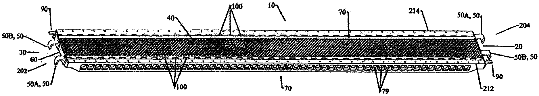
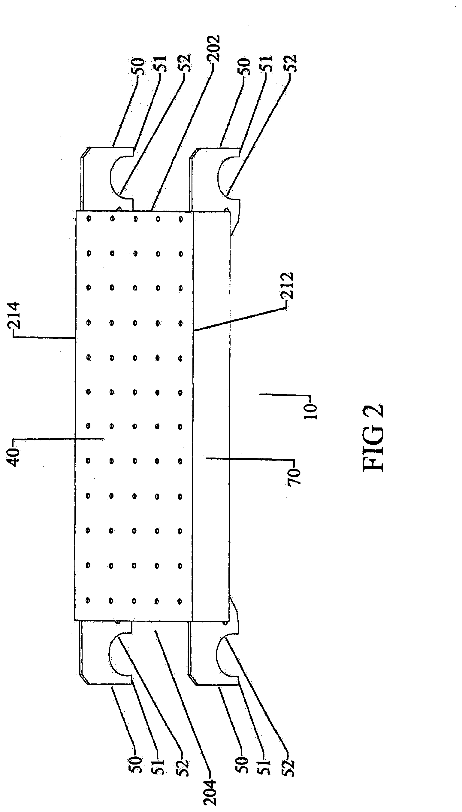
[0004] Once a scaffold frame is erected, an elevated work surface is created by using scaffold boards that are supported at each end of the board by horizontal scaffold frame members. Typically, scaffold boards or planks are wooden, fiberglass, or metal board-like members, having a length (such as 10 feet) and a width, such as 9 inches. A scaffold board generally comprises a top surface, such as 6 inch, 9 inch, 12 inch, or 18 inch wide board, and come in various lengths, such as 2 feet long to 10 to 16 feet long. A typical metal scaffold board is shown in FIG. 2, showing a metal plank 1, having a top surface 40, and two side rail extensions 70 extending downwardly at about 90 degrees to the top surface 1 adjacent the edges of the top surface. The top surface 40 can be a solid surface, a surface with drain holes, or formed from a series of metal plates (see FIG. 3). The scaffold plank side rails 70 may be integrally formed with the top surface (such as by roll forming the plank from a single piece of metal), or may be separately attached, such as by welding, riveting, etc. Each metal board top surface has two terminating ends, (a first terminating end edge 202 and a second terminating end edge 204 (not shown)). The edge is linear, but may be curved. Also shown in FIG. 2, the board 10 has a first top side edge 212 and a second top side edge 214. Located near each terminating end edge 204, 206 is at least one (preferably two or more) clip members 50. As shown in FIG. 2, one embodiment of clip members 50 are shaped plate members with a downwardly facing channel 52 rearward of downward lip section 51. The channel 52 is shaped to engage a horizontal scaffold member in a channel 52 or cutout section (not shown). As shown, the clips are vertical orientated plate members, one attached to each side rail 70. The clips can be "L" shaped member, "U" or "C" or other "hook" type of engagement members. In the embodiment shown in FIG. 2, each clip 50 has a leading downward facing lip portion 51 (forming a hook-like structure) and a downward facing channel 52 behind the lip, together forming a "U" shaped clip or cleat 50. The channel 52 is located between the lip 51 and the adjacent terminating edge 202 or 204 of the scaffold board. The channel 52 may end before the respective terminating end edge 202 or 204, or at the terminating end edge, or in other embodiments, behind the terminating end edge.
[0005] When a scaffold board 10 is placed in a scaffold structure, the clip channel 52 will rest or engage a horizontal scaffold member, thereby supporting the scaffold plank 10. The clips 50 can be vertical orientated plates, such as shown in FIG. 2, or the clip plates 50 may be substantially horizontally oriented formed or shaped plates, such as shown in FIG. 4, or the clips may be square or circular or other shapes in cross section to couple with a horizontal scaffold member or another scaffold plank. The scaffold elevated work surface generally forms a continuous uninterrupted surface, with safety railing surrounding the work deck or work surface. Often however, the elevated surface may have to be constructed around a structure or obstacle. For instance, pipes, chimneys or conduits may need to extend through the work deck. An obstruction that penetrates through the deck of a scaffold deck will leave an opening in the deck, where the length of the opening corresponds to that of the adjacent scaffold board, as depicted in FIG. 5, a top view of a deck with a conduit extending through the deck area. To close the resulting opening, often wooden scaffold boards are used across the opening, where the boards are placed across the metal planks (for instance, at 90 degrees to the metal planks). However, the wooden planks are a tripping hazard.
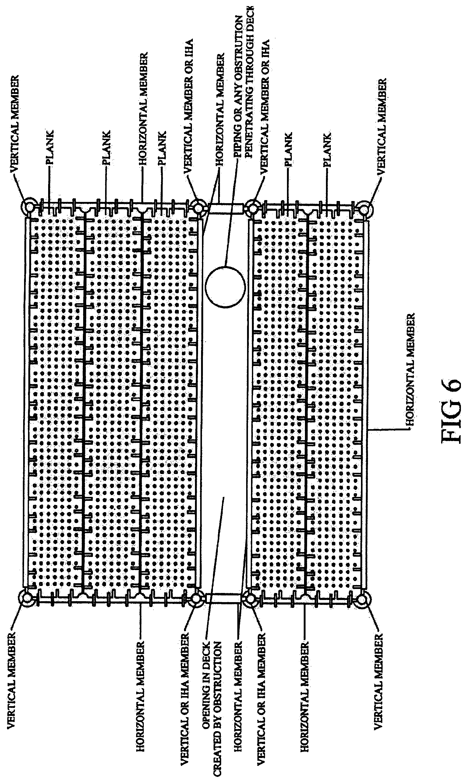
[0006] Alternatively, two "interior" horizontal scaffold members can be positioned in the interior of the frame, on opposite sides of the obstruction (which will require additional vertical members, as the horizontal members generally couple to a vertical scaffold member. particularly in system scaffolding). Note, however, the "additional vertical scaffold member" can be an intermediate scaffold joint, one embodiment of which is as disclosed in U.S. Pat. No. 8,973,711, hereby incorporated by reference in its entirety, to create a frame structure to allow placement of short scaffold planks at right angles to the existing scaffold planks, to thereby close the opening created by the obstacle. This is depicted in FIG. 6 and FIG. 7. A better system is needed to accommodate openings in scaffold decks.
BRIEF DESCRIPTION OF THE DRAWINGS
[0007] FIG. 1 is a cartoon perspective of a scaffold system with elevated deck.
[0008] FIG. 2 is a side perspective view of a prior art high profile scaffold board.
[0009] FIG. 3 is top perspective view of another prior art high profile scaffold board.
[0010] FIG. 4 is a top perspective view of one end of one embodiment of the improved low profile scaffold boards.
[0011] FIG. 5 is a top view of a scaffold decking penetrated by an obstacle.
[0012] FIG. 6 is a top view of a scaffold decking of FIG. 5 with intermediate horizontal scaffold members laid in the perimeter of the opening.
[0013] FIG. 7 is a top view of a scaffold decking of FIG. 6 with scaffold planks laid across and supported by the intermediate horizontal scaffold members.
[0014] FIG. 8 is a top perspective view of one embodiment of an improved low profile scaffold board.
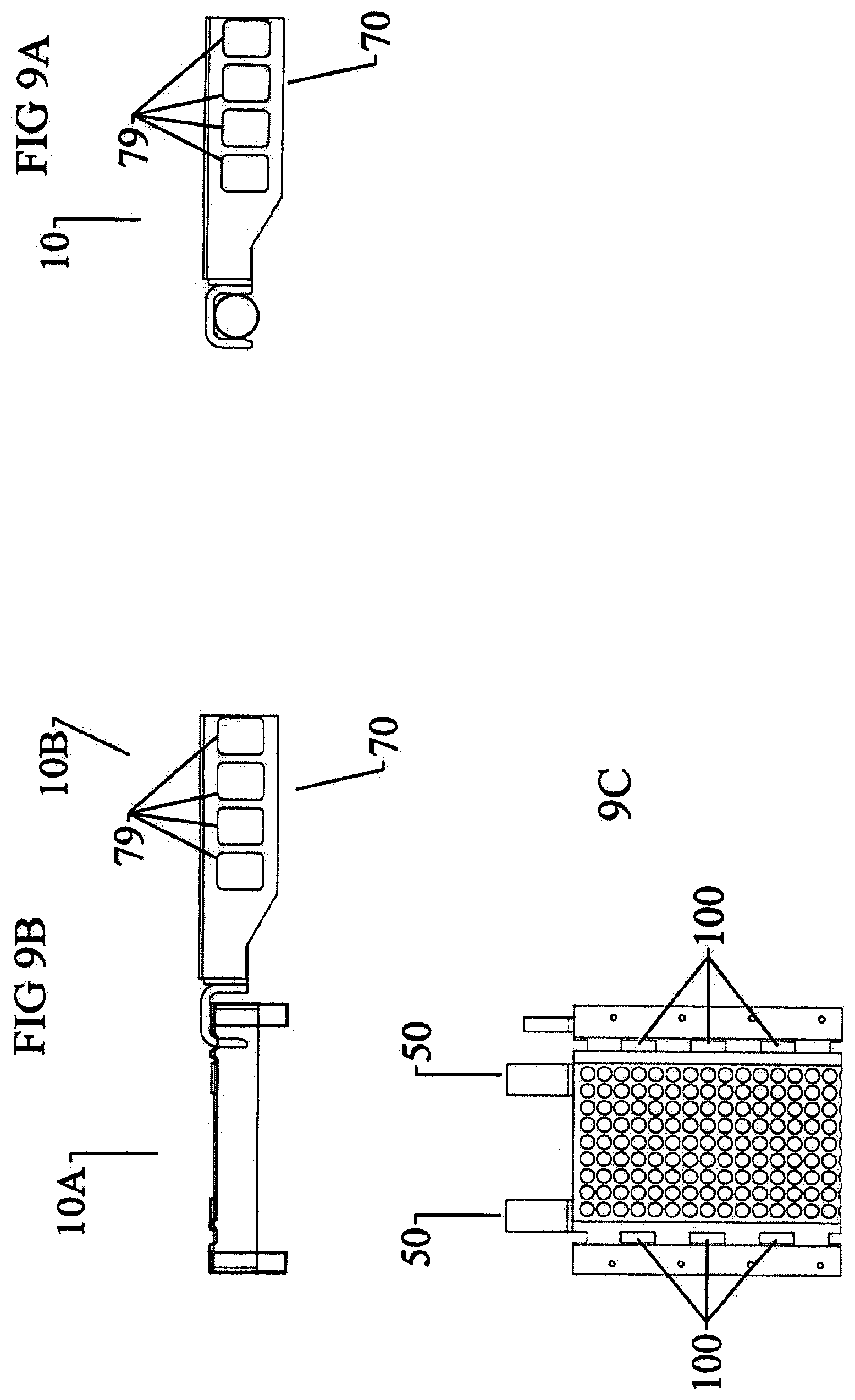
[0015] FIG. 9A is a side elevation view of one end of the scaffold board of FIG. 8.
[0016] FIG. 9B is a side elevation view of two scaffold boards as in FIG. 8 coupled together in a side-to-end configuration.
[0017] FIG. 9C is a top elevation view of one end of the scaffold board of FIG. 8.
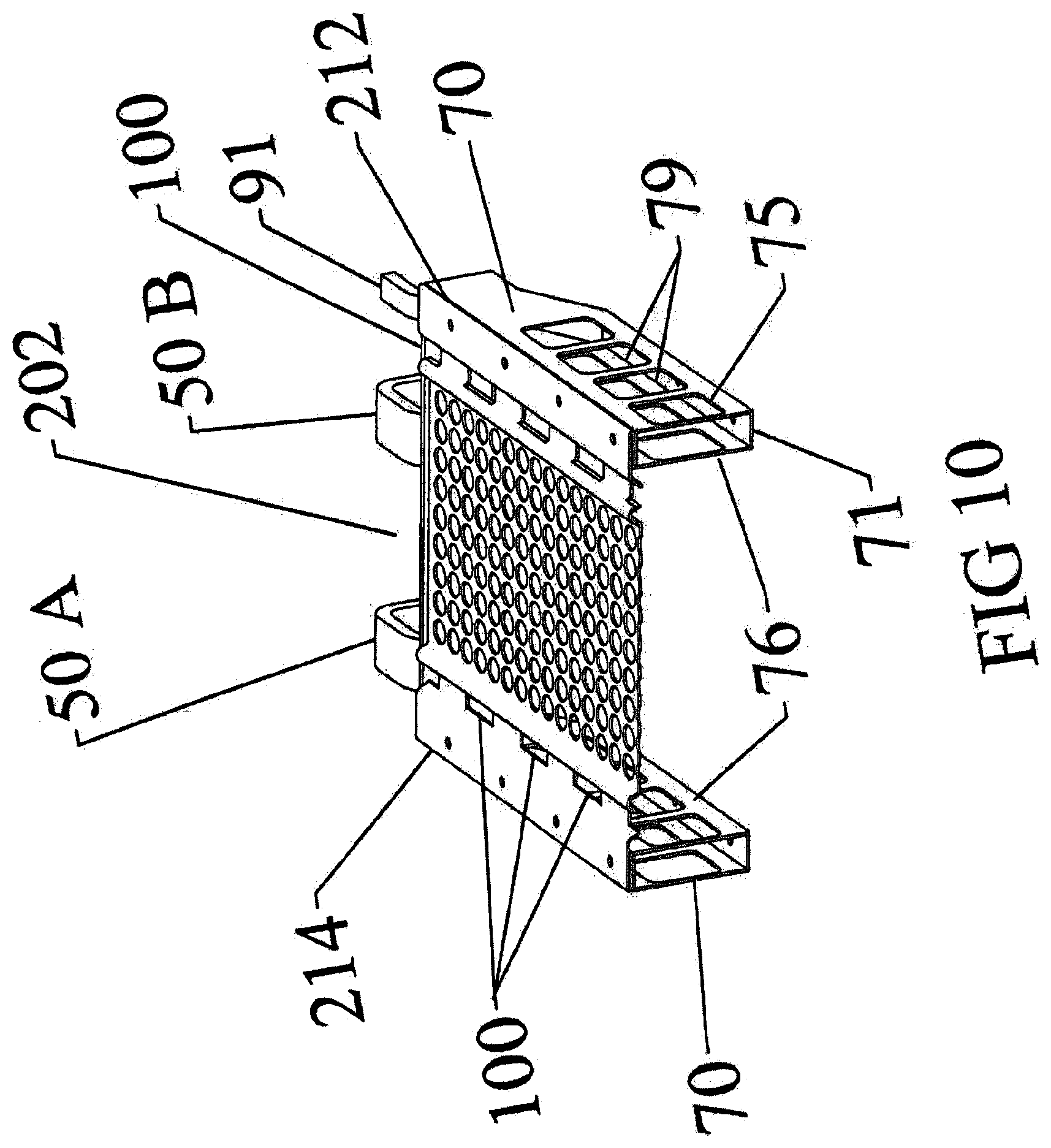
[0018] FIG. 10 is a top perspective view of a cross section through the scaffold board of FIG. 8.
[0019] FIG. 11A is a top elevation view of another embodiment of the improved scaffold board.
[0020] FIG. 11B is a side elevation view of the scaffold board of FIG. 11A.
[0021] FIG. 11C are side elevation views of different embodiments of low profile clips.
[0022] FIG. 11D are end views of the scaffold board of FIG. 11A, with 11D-1 showing an end view of the top portion, 11D-3 showing an end view of the bottom portion, and 11D-2 showing an end view of the assembled bottom and top portion.
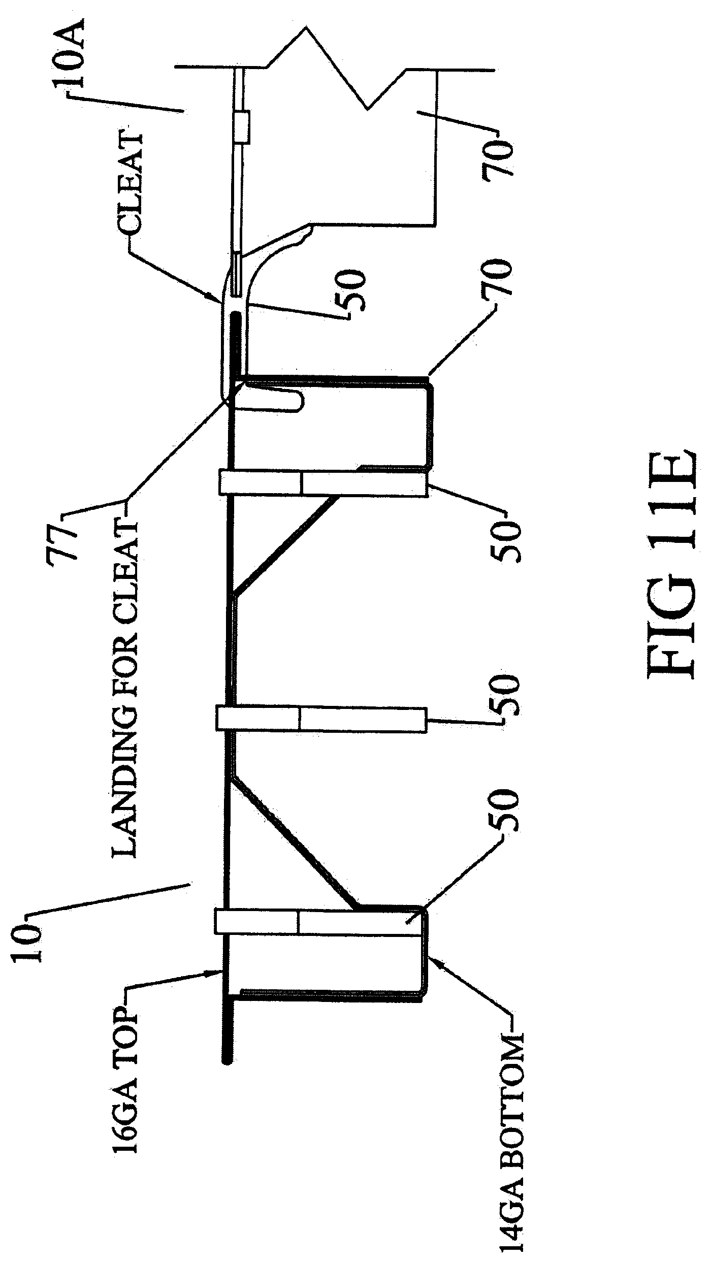
[0023] FIG. 11E is a side elevation view of two of the scaffold boards of FIG. 11 coupled together in an end-to-side configuration.
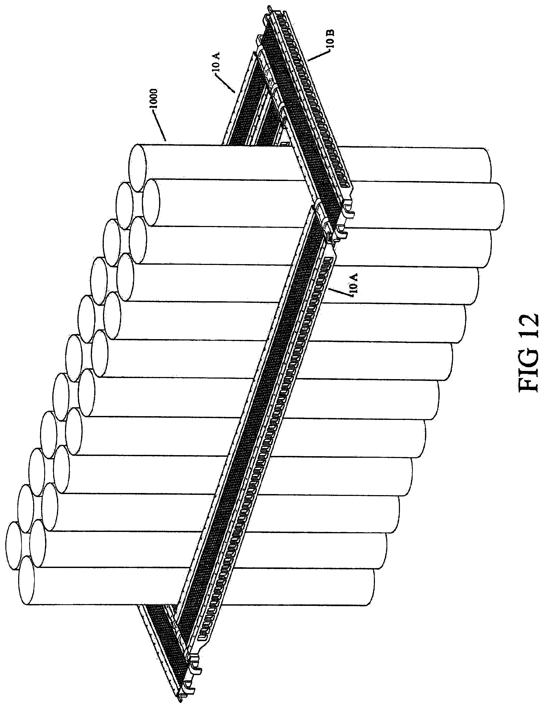
[0024] FIG. 12 is a perspective view depicting an embodiment of the improved boards in aside-to-end configuration around an obstacle.
[0025] FIG. 13 is a top perspective view of a scaffold deck depicting joining a series of scaffold members (10-1 through 10-7) to two adjacent improved scaffold members (10-C and 10-D) in a side to end configuration.
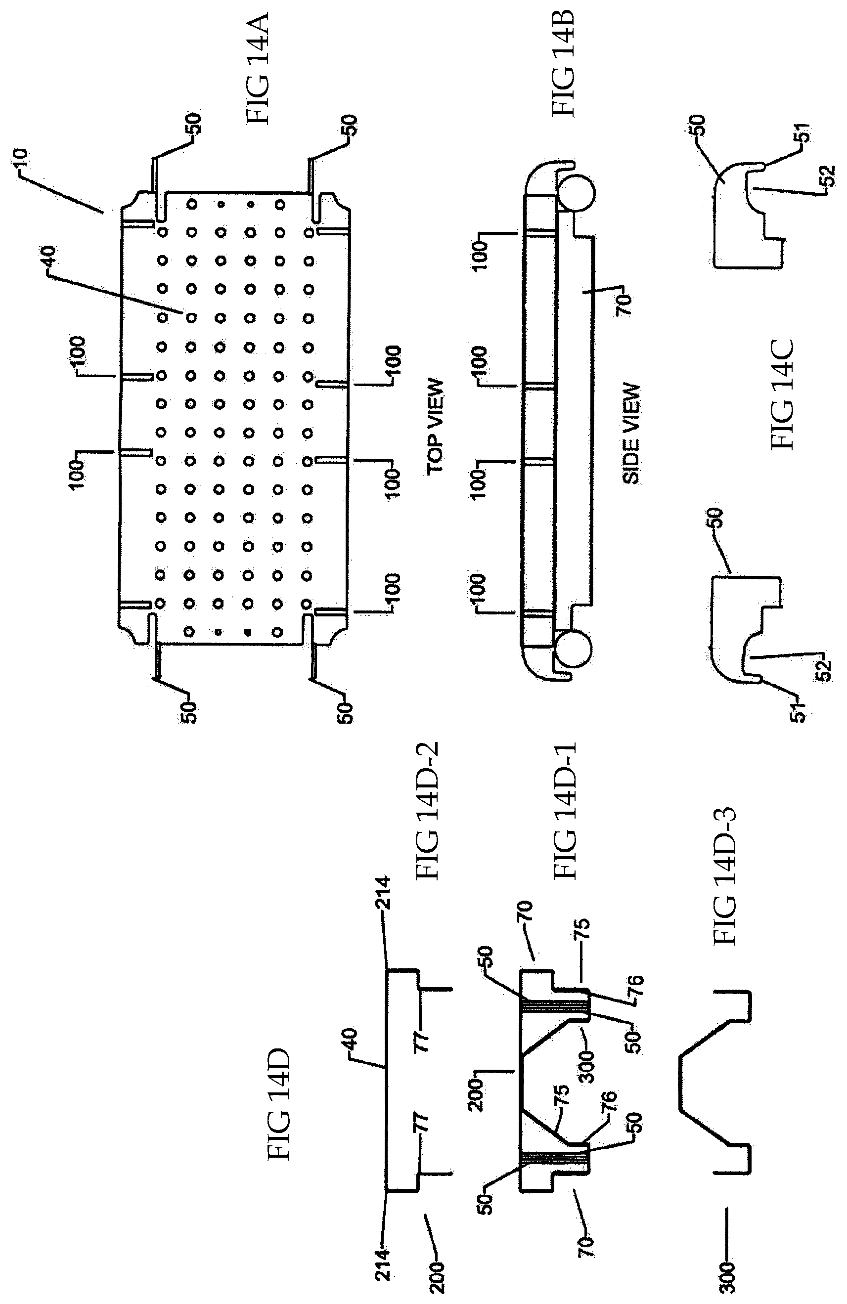
[0026] FIG. 14A is a top elevation view of another embodiment of the improved scaffold board (a high profile configuration).
[0027] FIG. 14B is a side elevation view of the scaffold board of FIG. 14A.
[0028] FIG. 14C are side elevation views of different embodiments of high profile clips.
[0029] FIG. 14D are end views of the scaffold board of FIG. 14A, with 14D-1 showing an end view of the top portion, 14D-3 showing an end view of the bottom portion, and 14D-2 showing an end view of the assembled bottom and top portion.
[0030] FIG. 14E is a side elevation view of two of the scaffold boards of FIG. 14 coupled together in an end-to-side configuration.
DETAILED DESCRIPTION OF THE INVENTION
[0031] The invention is an improved scaffold plank. As shown in the view of FIG. 8, one embodiment of the plank is a board like member 10, having a first and second terminating ends 202, 204, first and second side edges 212, 214, a top surface 40 extending between the two terminating ends and two side rails 70, extending downwardly from the top surface at about 90 degrees, running substantially the length of the board 10, and are positioned on the scaffold board near the side edges 202 and 214. Positioned at or near terminating ends 202, 204 is at least one shaped clip 50, shaped to couple with a horizontal scaffold member. Generally, the clips are "L," "U" or "C" shaped plates extending outwardly from the terminating ends of the plank 10. As shown in FIG. 8, the clips 50 are attached to an end brace 60 that extends between the side rails 70 of the plank 10. The clips 50 could also be attached to the top surface 40, or side rails 70, or be integrally formed with the top surface or rails. In the embodiment shown, the clips 50 are flat metal plates bent in a "U" shape, where the plate is orientated substantially horizontally (as opposed to orientated in a vertical orientation, such as shown in FIG. 2). The horizontal orientation of the clip 50, where the top of plate above the channel 52 is approximately at the height of the top surface 40 of the plank, allows for the top surface 40 of the plank to closely align with the top surface of a supporting horizontal member, such as shown in FIG. 9A. The top surface 40 shown is formed from a metal plate, such as 16 gauge steel, with drain holes there through.
[0032] As can be seen in FIG. 8, in one embodiment, the clips 50 on opposite terminating ends are not aligned, but are offset to accommodate placement of scaffold boards "end-to-end" lengthwise on the same horizontal scaffold member. On each terminating end 202 and 204, one clip 50A is positioned near a side rail 70, while the other clip 50B is offset and interior to the board from the opposing side rail 70. Also shown is optional tab 90, which projects from the top surface of the board 40, and has a thickness of a clip. The tab 90 is placed near the inward clip 50B, to resist rotation of the board on the supporting horizontal scaffold member of supporting board member. Tab 90 is positioned so not to interfere or overlap with an adjacent scaffold board clip when placed end-to-end lengthwise or in an end-to side configuration shown in FIG. 10.
[0033] As shown in the embodiment of FIG. 8, side rails 70 are positioned adjacent the top surface 40 near the first and second top side edges 212, 214 to provide stiffening or a truss like component to the board 10. In one embodiment, shown in FIG. 10, the side rails 70 are shaped frame members, shaped with a bottom facing foot 71. Each side rail 70 has at least one outward facing surface 75, and one inward facing surface 76. The side rails 70 can be integrally formed with the top surface 40, such as by roll forming, or the side rail 60 may be attached to the top of the plank 40, such as by welding or with rivets or other mechanical attachment means. The side rails 70 can be a more complex assembled structure having multiple "rails" or shaped metal pieces, with multiple inward facing surfaces 76 and multiple outward facing surfaces 75, such as shown in FIG. 11. As shown in his cross section, the board is of two piece construction. The top 40 of the board 10 is formed with first downward side rails, 70A (FIG. 11A). The bottom of the board, 43, is a second piece, formed with second upward side rails 70B (FIG. 11B). The top and bottom are combined in the assembled board 10 (shown in FIG. 11C), such as by welding the top piece to the bottom piece. As shown in FIG. 8, the side rails 70 may also have openings 79 therethrough. The openings 79 reduce the weight of the board 10. If openings 79 are included in the side rails 70, preferably the openings 79 are suitably sized to allow for placement of a "slick tube" (a smooth tubular member lacking typical horizontal end connectors) through the openings, so that adjacent boards can be coupled with the slick tube, providing additional strength and stiffness to the decking formed from the scaffold boards.
[0034] The top surface 40 of the scaffold board 10 also has a series of openings or slots 100. In the embodiment shown in FIG. 8, the slots 100 are placed near but offset from the top side edges of the board, generally with at least a portion of the slot 100 extending inwardly (or behind) at least outwardly facing surface 75 of the side rails. In the embodiment shown, the slots 100 are aligned parallel with the side rails 70. The slots 100 in this embodiment are located at a specific distance inward from the top edges of the board, and sufficiently sized to allow placement of a clip 50 of a second scaffold board, orientated at 90 degrees, through a slot 100, as shown in FIG. 9B. In this configuration, two boards are coupled together in an "end-to-side" configuration, with the "end" of one board coupled to the "side" of a second board, allowing for two boards to be coupled to each other at about 90 degrees, without an intervening horizontal scaffold member. As shown in this figure, the slot 100 in this embodiment is orientated so that the lip 51 of the clip 50 of the second board extends through the slot, and the channel cut out of the second board is supported by the first scaffold board's top surface 40. The slots 100 are configured to allow such board-to-board coupling, where the coupled boards are orientated at 90 degrees to one another with the top surface of the coupled boards being adjacent, but preferably not overlapping. As shown in FIG. 12, one board 10B is coupled to an adjacent board 10A, at 90 degrees to board 10A, where the clips 50 on board 10B mate with slots 100 on board 10A. This board-to-board coupling does not require an intervening horizontal member (such as would otherwise be required, as shown in FIG. 7).
[0035] As shown in FIG. 13, a decking can be formed by coupling some board members to horizontal scaffold members (board 10-A, 10-B, 10-C and 10-D), while coupling other boards (10-1, 10-2, 10-3, 10-4, 10-5, 10-6 and 10-7) at 90 degrees to certain (boards 10-C and 10-D) of the boards supported by horizontal scaffold members. As shown in FIG. 12, such board-to-board coupling allows for placement of a scaffold structure around obstructions, such as pipes 1000. In the embodiment shown in FIG. 9B, the coupled board 10B top surface is slightly higher than the adjoining board 10A top surface. These surfaces can be aligned if the side edge of the board 10A, immediately adjacent the openings 100, are formed (such as by roll forming) to be slightly depressed from the top surface 40 of the board (depressed the thickness of the clip plate 50, for instance). The improved scaffold boards can be combined with existing scaffold boards, or used alone, to create scaffold decking. The placement of the clips 50 on the end edges of each board can be varied, and the number of clips can be varied. As shown, the slots 100 are uniformly distributed, but this also can be varied. For instance, a board may have one terminating end containing three clips spaced in the center of a board, while the other terminating end of the board has two clips located near opposing side rails. The openings or slots 100 in the plank do not have to be uniformly spaced, but are located and spaced to couple with the respective clips. In certain embodiments, slots 100 may also be present in the ends of the boards to accommodate end-to-end placement, such as shown in the embodiment shown in FIG. 14, later described.
[0036] If the board is constructed with clips 50 positioned vertically on the side rails (such as shown in FIG. 2), the desired openings or slots 100 in the top portion of the board may be slots that start at the board side edge, and extend from the edge inwardly toward the center of the board, such as shown in FIGS. 14 and 11) (FIG. 14 shows a high profile board, while FIG. 11 shows a low profile board). In these two embodiments, the clips on the high profile board are vertically oriented plates, while the clips on the low are also vertical plates but of thicker material, as the top of the clip above the channel is thinner, but must still be sufficiently strong to support the scaffold board. Instead of plates, the clips could also be formed from square or rectangular rods. As shown in this embodiment in FIGS. 14E and 11E, the cleats or clips 50 on the board supported board 10A extend partially through the side rail 70 of the supporting board 10B, through the slide slits 100 on the supporting board. The slots 100 partially extend through the side rail 70, but generally, not completely through the side rail 70, as the side rail 70 (or a portion thereof) will support the coupled board, as depicted in FIGS. 14E and 11E. The side rail, as shown, has an inverted or upside down "L" shape, (both sides therefore forming a "T" shaped board in cross section) where the leg of the L is positioned near the top surface of the board. The height of this top leg of the L should preferably closely match the height of a clip above the associated channel plus the thickness of the top surface. This height allows a side to end configuration to have the two adjoining top surfaces of the boards to be level or almost level with each other. The length of the top leg of the L should closely match the length of the channel of a clip from the inner edge of the downwardly projecting lip to the adjoining end edge of the associated board. This length allows two boards, in a "side to end configuration" to be positioned so that the side edge of the supporting board is almost immediately adjacent to the end edge of the supported board. That is, the two top surfaces of the boards will be adjacent, with only a small gap between the boards in a side to end configuration. Proper dimensioning allows a clip to rest on the side wall and allow the two top surfaces to be closely aligned. Using one or more pieces, such as the top and bottom pieces shown in FIGS. 14D and 15D, provides strength and rigidity to the side rail to assist to support a board on such side rails.
[0037] Details of these boards are shown in the remaining portions of FIGS. 14 and 11. For instance. As shown in FIG. 14D, the board 10 is formed from a top piece 200 and a bottom piece 300. Both top and bottom pieces have side rail extension portions 70. On the top piece 100, the side rail extension 70 includes a ledge portion 77 where the side rail portion bends inwardly 80 degrees. The slots 100 in the top of the board extend through the top side rail portion, but preferably not through the bottom side rail portion. When a board supports another board in an end-to-side configuration, the side supported board's clips will extend through the slots in the supporting board, to terminate and rest (and be supported by) the ledger 77, as shown in FIG. 14E.
[0038] When vertical clips are used, the two terminating ends of the scaffold board may be mirror images, or almost mirror images, as the offset needed for horizontal clips is not required for end-to-end positioning. See FIGS. 14A and 11A. As shown, the terminating ends, 204 and 202 are also shown with slots 100. These terminating slots allow two boards, placed in an end-to end relationship (where both boards are supported by the same horizontal scaffold member), to have the adjoining top surfaces 40 located adjacent to each other with little or no gap between the adjoining boards (not shown).
[0039] To assemble boards in a side-to-end configuration in an existing scaffold frame structure, a first scaffold plank utilizing the slotted openings is positioned in a scaffold structure, supported on each of its terminating ends by opposing horizontal scaffold members. A second scaffold plank (which may lack the slotted openings 100, but has end clips 50) is positioned at 90 degrees to the first scaffold plank, with the clips at a first end of the second board positioned above corresponding slots 100 of the first scaffold board (i.e., those slots along the side edge of the first board). The second scaffold board is lowered, so that the clips at the first end of the second board partially pass through the aligned slots or openings in the first board, until the first end of the second scaffold board member is supported by the first scaffold board. One end of the second board is now coupled to, and supported by, the first board, without an intervening horizontal member between the first and second board members. The clips on the second end (the distal end) of the second board may be supported by a another horizontal scaffold member, or supported by a third scaffold board orientated 90 degrees to the second scaffold board, with the third scaffold board having slots that align with the clips at the second terminating end of the second scaffold board.
[0040] While the illustrative forms disclosed herein have been described with particularity, it will be understood that various other modifications will be apparent to and can be readily made by those skilled in the art without departing from the spirit and scope of the disclosure. For instance, the improved board may have only a single side adapted with slots to support a board in a side to end configuration. Accordingly, it is not intended that the scope of the claims appended hereto be limited to the example and descriptions set forth herein, but rather that the claims be construed as encompassing all the features of patentable novelty which reside herein, including all features which would be treated as equivalents thereof by those skilled in the art to which this disclosure pertains.
[0041] When numerical lower limits and numerical upper limits are listed herein, ranges from any lower limit to any upper limit are contemplated.
* * * * *
D00000
D00001
D00002
D00003
D00004
D00005
D00006
D00007
D00008
D00009
D00010
D00011
D00012
D00013
D00014

D00015
D00016

XML
uspto.report is an independent third-party trademark research tool that is not affiliated, endorsed, or sponsored by the United States Patent and Trademark Office (USPTO) or any other governmental organization. The information provided by uspto.report is based on publicly available data at the time of writing and is intended for informational purposes only.
While we strive to provide accurate and up-to-date information, we do not guarantee the accuracy, completeness, reliability, or suitability of the information displayed on this site. The use of this site is at your own risk. Any reliance you place on such information is therefore strictly at your own risk.
All official trademark data, including owner information, should be verified by visiting the official USPTO website at www.uspto.gov. This site is not intended to replace professional legal advice and should not be used as a substitute for consulting with a legal professional who is knowledgeable about trademark law.