Lid
Lee; Yu Ting ; et al.
U.S. patent application number 16/546263 was filed with the patent office on 2020-02-20 for lid. The applicant listed for this patent is Lollicup USA, Inc.. Invention is credited to Chia-Chen Hsu, Yu Ting Lee.
| Application Number | 20200055640 16/546263 |
| Document ID | / |
| Family ID | 69524490 |
| Filed Date | 2020-02-20 |


| United States Patent Application | 20200055640 |
| Kind Code | A1 |
| Lee; Yu Ting ; et al. | February 20, 2020 |
LID
Abstract
Lids for cups. In preferred embodiments, lids which are installable on cups which provide hybrid functionalities. In still more preferred embodiments, hybrid drinking cup lids for installation on a cup which are structurally configured to include a drink through portion and a straw receiving portion; the drink through portion and the straw receiving portion being alternately useable for optionally drinking without a straw or for optionally drinking with a straw. In the most preferred embodiments the straw receiving portion is configured and located to reduce mechanical wear on inserted straws, such as paper straws, during use.
| Inventors: | Lee; Yu Ting; (New Taipei City, TW) ; Hsu; Chia-Chen; (New Taipei City, TW) | ||||||||||
| Applicant: |
|
||||||||||
|---|---|---|---|---|---|---|---|---|---|---|---|
| Family ID: | 69524490 | ||||||||||
| Appl. No.: | 16/546263 | ||||||||||
| Filed: | August 20, 2019 |
Related U.S. Patent Documents
| Application Number | Filing Date | Patent Number | ||
|---|---|---|---|---|
| 62765211 | Aug 20, 2018 | |||
| Current U.S. Class: | 1/1 |
| Current CPC Class: | B65D 2543/00092 20130101; B65D 2543/00527 20130101; A47G 19/2272 20130101; B65D 43/0212 20130101; B65D 2543/00027 20130101; B65D 2543/00537 20130101; B65D 2543/00601 20130101; B65D 2543/00046 20130101 |
| International Class: | B65D 43/02 20060101 B65D043/02; A47G 19/22 20060101 A47G019/22 |
Claims
1. A lid comprising: an annular lower cup lid engaging portion comprising a circumferential skirt including a first portion comprising an angled annular wall angled at a selected angle to engage with a lip of a cup and to guide said lid to a position substantially centered on a cup to which said lid will be installed and a second portion angled in a second direction at a second angle, the intersection of the first portion and the second portion being plastically deformable such that the intersection of angles deforms when pressed against a cup lip and snaps over said cup lip to retain said lid on said cup lip to accomplish fixation of said lid to the cup; a cup lip retaining portion extending around the circumference of said lid; an upwardly extending raised annular lid portion, located inboard of said cup lip retaining portion, having a first portion having a first height and having a second portion having a second height which is raised relative to said first height of said first portion; said second portion configured to receive a lower lip of a user, the second portion having a substantially smooth surface to obtain a liquid tight seal between a lower lip of a user and the second portion; a planar top portion located inboard of said upwardly extending raised annular lid portion; a tab having two non-parallel sides, said configuration of said two non-parallel sides of said tab resulting in said tab having a wide end and a narrow end, and said tab having a third side located proximal said second raised annular lid portion, said two non-parallel sides and said third side of said tab each being disconnectably affixed to said planar top portion such that said third end and said two non-parallel sides may be disconnected from said planar top portion such that said tab can be bent in a direction away from said second raised annular lid portion to expose a tab drink opening; said tab further including a male protrusion; said planar top portion having a female receptacle portion; said tab being securable in an open position by press fitting said male protrusion into said female receptacle portion; a cross-cut portion in line with and located generally opposite of said tab on said planar top portion, said cross-cut portion being comprised of a first linear cut which goes partially but not entirely through said planar top portion in at least one region of said linear cut; a second linear cut which transects the first linear cut at an intersection point and which is oriented approximately perpendicular thereto; the intersection point of said cross-cut portion being located substantially spaced from a centerline of said lid and also located at a selected distance D inboard of said cup lip retaining portion; said cross-cut portion being puncturable by a straw to form a straw receptacle for use to drink liquid using a straw and, in the alternative, puncturable to serve as a vent hole to allow air to escape during drinking through said tab drink opening to improve drinking flow; and said selected distance D being so selected such that when a straw is installed in said cross-cut portion of said lid, and when said lid is installed on a cup, said cross-cut portion of said lid locates a lower end of said straw proximal a side wall of said cup thereby restricting movement of said straw, in at least one direction, when inserted in said cross-cut portion of said lid, thereby reducing mechanical wear on said straw.
2. A lid according to claim 1 wherein said intersection point of said cross-cut portion is located outboard of a midpoint between said centerline of said lid and said cup lip retaining portion.
3. A lid according to claim 1 wherein said distance D is a value less than 50 percent of the distance from said cup lip retaining portion to said centerline of said lid.
4. A lid according to claim 1 wherein said distance D is a value approximately 45 percent, or less, than the distance from said cup lip retaining portion to said centerline of said lid.
5. A lid according to claim 1 wherein said distance D is a value approximately 40 percent, or less, than the distance from said cup lip retaining portion to said centerline of said lid.
6. A lid according to claim 1 wherein said distance D is a value approximately 1/3rd, or less, than the distance from said cup lip retaining portion to said centerline of said lid.
7. A lid according to claim 1 wherein said distance D is a value selected from between approximately 6-25 millimeters.
8. A lid according to claim 1, combined with a beverage cup and paper straw, wherein said lid is installed on said cup, and wherein said paper straw is inserted in said straw receptacle formed by puncturing said cross-cut portion of said lid.
9. A method of using the lid, paper straw, and beverage cup combination according to claim 8, wherein when said paper straw is used by a human user to drink a beverage carried by said beverage cup, dynamic mechanical wear on said paper straw is reduced, improving longevity of said paper straw.
Description
RELATED APPLICATION DATA
[0001] This application claims priority to U.S. Provisional Patent Application No. 62/765,211, filed on Aug. 20, 2018, and also entitled LID. The entirety of such application is hereby incorporated by reference.
FIELD OF INVENTION
[0002] This invention relates, in at least one embodiment, to lids for cups. In preferred embodiments, this invention relates to lids which are installable on cups which provide hybrid or improved functionalities.
BACKGROUND OF THE INVENTION
[0003] The use of disposable lids on disposable cups has been ubiquitous for decades. Such lids, in the case of cold cup lids, have heretofore typically included straw apertures for the insertion of a plastic straw so that a beverage can be accessed from the cup using the straw, for sake of drinking enjoyment and convenience. However, in recent times the widespread use of disposable straws--particularly those made of plastic--has become an environmental concern. This environmental concern is heightened because cold cup lids, and the cups they are installed on, are often also disposable. Therefore, the use of disposable straws collectively with disposable cups and lids, has been acknowledged to have a negative impact on the environment, particularly when the articles are not disposed of properly by the end user.
[0004] Addressing these concerns, in very recent times, straw manufacturers have begun to manufacture straws out of paper products, instead of the plastic type variants conventionally used. Although such paper straw products are more environmentally friendly, they present their own problems. For example, paper straws are significantly less durable than plastic straws (which are nearly indestructible) whereas the typical paper straw, when used in a conventional cold cup lid, has a useable lifespan of only approximately twenty minutes. This is because conventional cold cup lids typically locate straw apertures at or near the center of the lid. Located near the lid center, significant back and forth movement of the lower (and/or upper) portion of an installed straw is mechanically permitted. Indeed, it is essential to the use of the lid/straw combination to ergonomically position the human user's head, relative to the beverage in the cup, for efficient drinking. This back and forth movement--in turn--results in high levels of mechanical wear on the straw, as the (typically sharp) edges of the aperture of the lid exert dynamic wearing forces on the outer straw surfaces.
[0005] Furthermore, although so-called drink-through type lids which allow a user to drink through an aperture in the lid, have been known in the art, as have been lids which include straw apertures, there exists a need or desire in the art for lids which provide both functionalities, and/or provide both functionalities combined with improved additional lid performances. Including both a drink-through function and straw receptacle function in one lid configuration, for example, reduces the amount of inventory that a lid manufacturer or re-seller must keep on hand to meet different consumer needs.
[0006] It is, in certain embodiments, a purpose of the herein described inventions to address one or more of the above drawbacks or needs in the art. It is also a purpose of the herein described inventions to address other drawbacks and/or other desires for improvements in the art, whether or not currently known, which will become more apparent to the skilled artisan once given the present disclosure.
SUMMARY OF CERTAIN EXAMPLE EMBODIMENTS OF THE INVENTION
[0007] Generally speaking, one or more of the inventions described herein provide lids which have configurations or functions which have been heretofore unknown in the art. One such lid embodiment is a dual-use lid configured to provide the hybrid functionalities of permitting strawless use, while also permitting the use of a straw when desired. In at least one embodiment of such invention, a lid is provided with a drink-through aperture and also with a straw receptacle so that the lid can be used in either drink-through or straw-mode as desired.
[0008] In other embodiments of the lids described herein, lids are provided which are designed to improve or increase paper straw performance and/or longevity. In at least one embodiment of such invention, a straw aperture is located spaced from the center-point (or centerline) of the lid. In more preferred embodiments, the straw aperture is located spaced proximal to the circumferential perimeter of the lid. In such embodiments, when a straw is inserted in the specially located straw aperture (with the lid installed on a cup), the lower-end of the straw is positioned proximal the side wall of the cup. This near-wall positioning utilizes the cup wall itself to restrict movement of the straw within the straw aperture. This restricted movement, in turn, reduces mechanical abrasion on an inserted straw which promotes improved straw longevity. This straw install location also places the lower end of straw--which is used for beverage intake--in the corner of the cup bottom where liquid beverage collects when the cup is tilted for drinking.
[0009] In at least one embodiment, there is provided: a hybrid drinking cup lid for installation on a cup which is structurally configured to include a drink through portion and a straw receiving portion; the drink through portion and the straw receiving portion being alternately useable for optionally drinking without a straw or for optionally drinking with a straw.
[0010] In at least one alternative embodiment, there is provided: a lid comprising: an annular lower cup lid engaging portion comprising a circumferential skirt including a first portion comprising an angled annular wall angled at a selected angle to engage with a lip of a cup and to guide the lid to a position substantially centered on a cup to which the lid will be installed and a second portion angled in a second direction at a second angle, the intersection of the first portion and the second portion being plastically (or otherwise) deformable such that the intersection of angles deforms when pressed against a cup lip and snaps over the cup lip to retain the lid on the cup lip to accomplish fixation of the lid to the cup; and an upwardly extending raised annular lid portion having a first portion having a first height and having a second portion having a second height which is raised relative to the first height of the first portion; the second portion configured to receive a lower lip of a user, the second portion having a substantially smooth surface to obtain a liquid tight seal between a lower lip of a user and the second portion; a planar top portion located inboard of the upwardly extending raised annular lid portion; a tab having a wide end and a narrow end, the tab having two non-parallel sides being disconnectably affixed to the planar top portion such that the wide end and the non-parallel sides may be disconnected from the planar top portion such that the tab can be bent backwards to expose a drink opening; the tab having a male protrusion; the planar top portion having a female receptacle portion; the tab being bendable backwards and securable in an open position to expose a drink opening by press fitting the male protrusion into the female receptacle portion; a cross-cut portion in line with and located generally opposite of the tab on the planar top portion, the cross cut portion being comprised of a first linear cut which goes partially but not entirely through the planar top portion in at least one region of the linear cut; a second linear cut which transects the first linear cut at an intersection point and which is oriented approximately perpendicular thereto; the intersection point being located substantially spaced from the centerline of the lid and inboard of the raised annular portion by a distance sufficient to restrict movement of an inserted straw; the cross cut being alternately puncturable by a straw for use to drink liquid using a straw or, in the alternative, puncturable to serve as a vent hole to allow air to escape during drinking to improve drinking flow.
[0011] In another embodiment, there is provided: a lid comprising: an annular lower cup lid engaging portion comprising a circumferential skirt including a first portion comprising an angled annular wall angled at a selected angle to engage with a lip of a cup and to guide the lid to a position substantially centered on a cup to which the lid will be installed and a second portion angled in a second direction at a second angle, the intersection of the first portion and the second portion being plastically deformable such that the intersection of angles deforms when pressed against a cup lip and snaps over the cup lip to retain the lid on the cup lip to accomplish fixation of the lid to the cup; a cup lip retaining portion extending around the circumference of the lid; an upwardly extending raised annular lid portion, located inboard of the cup lip retaining portion, having a first portion having a first height and having a second portion having a second height which is raised relative to the first height of the first portion; the second portion configured to receive a lower lip of a user, the second portion having a substantially smooth surface to obtain a liquid tight seal between a lower lip of a user and the second portion; a planar top portion located inboard of the upwardly extending raised annular lid portion; a tab having two non-parallel sides, the configuration of the two non-parallel sides of the tab resulting in the tab having a wide end and a narrow end, and the tab having a third side located proximal the second raised annular lid portion, the two non-parallel sides and the third side of the tab each being disconnectably affixed to the planar top portion such that the third end and the two non-parallel sides may be disconnected from the planar top portion such that the tab can be bent in a direction away from the second raised annular lid portion to expose a tab drink opening; the tab further including a male protrusion; the planar top portion having a female receptacle portion; the tab being securable in an open position by press fitting the male protrusion into the female receptacle portion; a cross-cut portion in line with and located generally opposite of the tab on the planar top portion, the cross-cut portion being comprised of a first linear cut which goes partially but not entirely through the planar top portion in at least one region of the linear cut; a second linear cut which transects the first linear cut at an intersection point and which is oriented approximately perpendicular thereto; the intersection point of the cross-cut portion being located substantially spaced from a centerline of the lid and also located at a selected distance D inboard of the cup lip retaining portion; the cross-cut portion being puncturable by a straw for use to drink liquid using a straw and, in the alternative, puncturable to serve as a vent hole to allow air to escape during drinking through the tab drink opening to improve drinking flow; and the selected distance D being so selected such that when a straw is installed in the cross-cut portion of the lid, and when the lid is installed on a cup, the cross-cut portion of the lid locates a lower end of the straw proximal a side wall of the cup thereby restricting movement of the straw, in at least one direction, when inserted in the cross-cut portion of the lid, thereby reducing mechanical wear on the straw.
[0012] In at least one example of the above-described embodiments, the intersection point of the cross-cut portion is located outboard of a midpoint between the centerline of the lid and the cup lip retaining portion. In some of these example embodiments, good (or at least improved) paper straw longevity is obtained when the distance D is a value less than 50 percent of the distance from the cup lip retaining portion to the centerline of the lid, with performance being further improved when the distance D is a value approximately 45 percent, or less, than the distance from the cup lip retaining portion to the centerline of the lid. In still other examples of these embodiments, the distance D is a value approximately 40 percent, or less, than the distance from the cup lip retaining portion to the centerline of the lid; or a value approximately 1/3rd, or less, than the distance from the cup lip retaining portion to the centerline of the lid. In certain sized lids, representing these example embodiments--such as lid having an example diameter of between 90-100 millimeters--the distance D is a value selected from between approximately 6-25 millimeters. Optionally, the distance D may be even further reduced, such as to between 0.5-6 millimeters.
[0013] In other embodiments of the invention, a lid (as described herein) is combined with a paper straw inserted through a straw receptacle of the lid, with the lid installed on a cup, to provide a unique and performance improved lid/straw/cup combination. In other embodiments, applicants consider the methods of using a lid as described herein, or the lid/straw/cup combination, to obtain improved drinking delivery performance and/or improved paper straw durability, as one or more other inventions.
[0014] Certain examples of the invention are now described below with respect to certain non-limiting embodiments thereof as illustrated in the following drawings wherein:
BRIEF DESCRIPTION OF CERTAIN EXAMPLE DRAWINGS
[0015] The drawings submitted herewith, and which form a part of this patent application, each illustrate an embodiment, or one or more components of an embodiment, of a non-limiting example of Applicant's inventive lids. While these drawings depict certain preferred embodiments of Applicant's invention, as well as certain particularly desirable features thereof, they are intended to be examples only and should not be construed to limit the scope of applicants' invention.
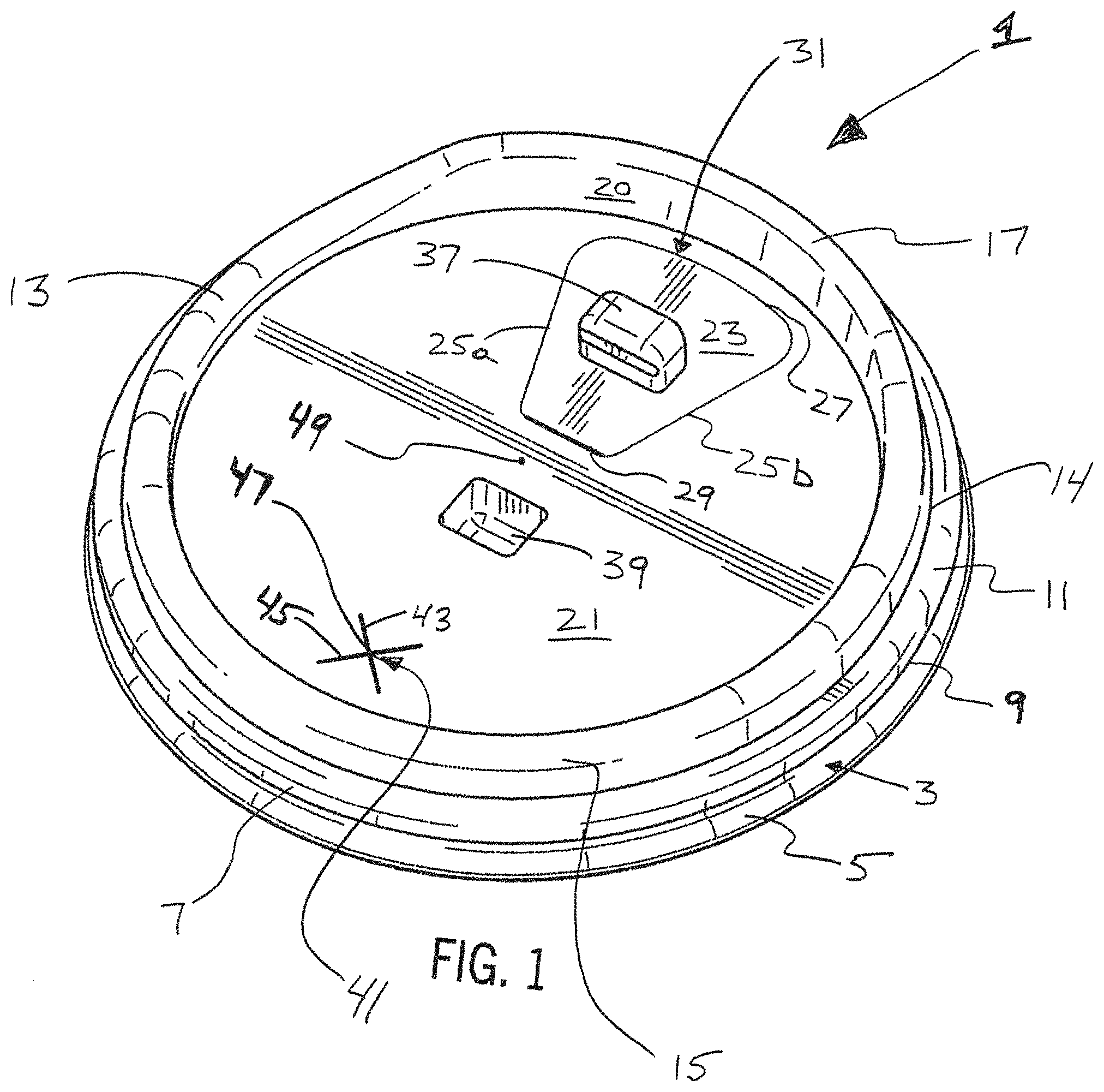
[0016] FIG. 1 illustrates a perspective view of one non-limiting embodiment of a lid according to the invention.
[0017] FIG. 2 illustrates an elevation view of the side of the lid illustrated in FIG. 1.
[0018] FIG. 3 illustrates an elevation view of the opposite side of the lid illustrated in
[0019] FIG. 2.
[0020] FIG. 4. illustrates an elevation view of the straw receptacle end of the lid illustrated in FIG. 1.
[0021] FIG. 5. illustrates an elevation view of the drink-through end of the lid illustrated in FIG. 1.
[0022] FIG. 6. illustrates a top view of the lid depicted in FIG. 1.
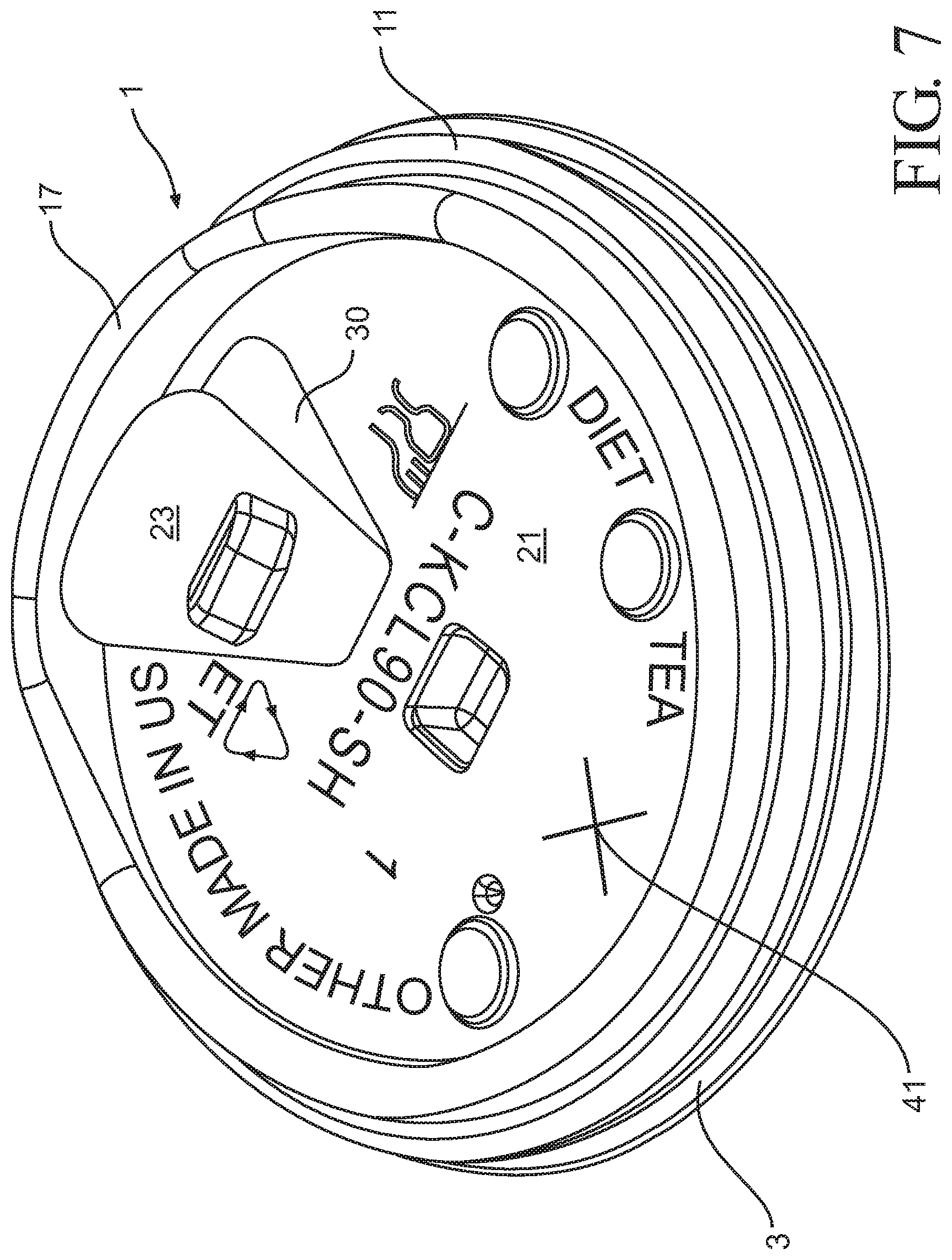
[0023] FIG. 7 illustrates a perspective view of another non-limiting embodiment of a lid according to the invention, with the pull-tear tab pulled open to expose an example drink-through aperture.
[0024] FIG. 8 illustrates the lid embodiment depicted in FIG. 1, installed on an example cup, with a paper straw installed in the provided straw receptacle.
[0025] FIG. 9 illustrates a prior art lid, cup, and straw combination.
[0026] FIG. 10 illustrates a cross-section of the lid depicted in FIG. 1, combined with a duplicate cross-section, to demonstrate a stacking function of such lid.
DETAILED DESCRIPTION OF CERTAIN EXAMPLE EMBODIMENTS OF THE INVENTION
[0027] For a more complete understanding of the present invention, reference is now made to the following description of various illustrative and non-limiting embodiments thereof, taken in conjunction with the accompanying drawings in which like reference numbers indicate like features. These example embodiments, disclosed and discussed below, will assist in a further understanding of the inventions described and claimed herein, but they are not intended to limit the scope of the invention in any way. Although dimensions are discussed in connection with some embodiments, not all embodiments are intended to be limited to such dimensions, and variants from such dimensions are of course contemplated.
[0028] Referring initially to FIG. 1, one example embodiment of a lid which addresses the above described problems in the art, or which provides other improvements, is illustrated therein. As illustrated, lid 1 has an overall circular configuration so that it may be installed on a cup 101 (see FIG. 8) having a conventional round opening at its top for receiving and dispensing liquid. For this purpose, the lower portion of lid 1 is formed by a circumferential skirt 3 which is designed to engage and grip a lip 103 of cup 101.
[0029] More specifically, skirt 3 comprises an annular wall 5 which is angled to provide a sloped surface to engage cup lip 103. Angled as such, the diameter of the lower edge surface of the (circular) annular wall 5 is sized slightly larger than the diameter of a cup lip onto which the lid will be installed. Moving up the sloped surface of the annular wall, however, the diameter of the circular surface decreases along the slope to provide a centering function when lid 1 is placed on cup lip 103. The upper region of skirt 3 is formed by a second annular wall 7 which joins wall 5 at intersection region 9. Intersection region 9 has a diameter which is less than the outer diameter of cup lip 103 but is plastically deformable so that if pressure is placed on lid 1, the lid will initially deform (to a greater diameter) and then snap in place onto lip 103 with the lip thereafter being secured to and retained by cup lip retaining portion 11.
[0030] Extending inboard and upwards from the cup lip retaining portion 11 is a raised annular lid region 13 having a first portion 15 raised to a first height and a second portion 17 raised to a second height greater than the first height. Inboard, in this context, means in a direction, from the reference point, towards the centerline of the lid. In the preferred embodiments illustrated, the higher second portion 17 is configured from a combination of two sloped surfaces bounding a centered constant height region. The higher second portion is also preferably configured to suitably conform to the shape of at least the lower lip of a human user, with the outward facing, convex raised surface being smooth, and sufficiently tall, to form a liquid tight seal with a lower lip. This aids in preventing spillage when a human user is drinking through the tab 23 of the lid, when used in the "drink-through" mode.
[0031] Forming the center panel of the lid, and inboard of the annular region 13, is a generally planar top panel 21 comprised of an integrated circular-shaped panel region. By the term integrated, it is meant that the lid is--in preferred embodiments--a one-piece lid which can be formed using techniques such as vacuum forming with lid molds. The planar top panel includes a center (or centerline) 49 as illustrated in FIG. 1. Although a dot-type mark is included in FIG. 1 to illustrate the location of the centerline, such a mark does not exist in a manufactured lid in general practice.
[0032] To enable drink-through functionalities in lid 1, a tab 23 is included in the planar top panel which can be opened (as described below) to reveal a drink opening 30 through which liquid beverage can be dispensed (see FIG. 7). In the embodiment illustrated, drink opening 30 is located inboard of but proximal to the height-raised portion 17 of annular lid region 13. Located as such, drink opening 30 and portion 17 work together cooperatively to provide an efficient drink delivery configuration where liquid beverage which exits drink opening 30 may be guided by the inboard, concave surface 20 of the raised annular portion 17, effectively aiding in guiding liquid beverage to the mouth of a human user.
[0033] Tab 23 is normally closed, however, and is formed in lid 1 by imparting cuts into the surface of planar top panel 21. The cuts imparted do not extend through the entire thickness of the tab, but are sufficiently deep such that a human user can use his/her fingers to pull the tab back to complete the separation of material surfaces for the purposes of mechanically separating tab 23 from top panel 21. This is typically done on at least 3 sides, to expose drink-through aperture 30. Also, for this purpose, at least one side or end--in this case end 29--is preferably left attached to planar top panel 21 so that the tab remains attached to the lid. This serves to prevent litter of lid parts, and also retains the tab to the lid, so the tab may be potentially re-closed. In optional alternative embodiments, however, the tab may be separated from planar top panel 21 on all sides, so that tab 23 may be disposed of once it is pulled back (i.e., opened to expose the drink opening).
[0034] In the preferred configuration illustrated, tab 23 is formed of two non-parallel sides 25a and 25b, a wide end (or side) 27, and a narrow end 29 (see FIG. 1). Configured as such, when sides 25a, 25b, and 27 are detached from top panel 21, drink opening 30 with the wide point nearest the concave, raised surface of lid portion 17 is formed. Narrow end 29 remains attached to panel 21, but tab 23 can otherwise be folded back in a direction towards lid center (or centerline) 49, to expose the specially conformed drink opening. This specialized opening configuration, in this preferred embodiment, directs flow of liquid beverage (during use) to the raised, concave surface of lid portion 17 to efficiently deliver liquid beverage to the engaged mouth of a human user. For embodiments in which it is desired to retain tab 23 attached to the cup lid, such as the embodiment illustrated in FIG. 1, a tab securing mechanism, for securing tab 23 in an open position, may also be included. For example, as depicted in FIG. 1, tab 23 includes a male-protrusion 37, and planar top panel 21 includes a female receptacle 39. Configured as such, when tab 23 is torn and bent back from top panel 21, protrusion 37 can be pressed into a friction-fit relationship with receptacle 39. In this friction-fit state, the tab is adequately secured to keep drink opening 30 exposed for drinking use. Conversely, when a human user is done drinking, protrusion 37 may be manually released from receptacle 39 so that tab 23 may be folded back to its original "closed" position to effectively close drink opening 30.
[0035] Just as lid 1 is useable as a drink-through style lid, the lid also includes a puncturable straw receptable region through which a straw may be inserted for "straw drinking". Specifically, as illustrated in FIG. 1, lid 1 includes a puncturable, cross-cut straw hole 41 formed by providing intersecting linear cuts 43 and 45, which bisect each other at intersection point 47. Each cut 43 and 45 is preferably deep enough in planar top panel 21 to weaken the region so that it may be easily punctured with a straw (or finger in other embodiments), but without penetrating panel 21 entirely. Designed as such, prior to the straw receptable being punctured, the closed (pre-puncture) configuration of the lid prevents beverage from spilling or splashing through the straw region when the lid is installed on a beverage filled cup.
[0036] As illustrated, puncturable straw receptacle 41 is, in this embodiment, located generally opposite tab 23. Moreover, in order to achieve at least certain of the advantages provided by the unique lid described, intersection point 47 of the receptacle is preferably located substantially spaced from the center (or centerline) 49 of the lid, but also at a selected distance D inboard of cup lip retaining portion 11 (see, e.g., FIG. 6). The term "inboard", as used in this context (as elsewhere), means in a direction towards the center 49 (or centerline) of lid 1. The value of distance D, in preferred embodiments, is particularly selected such that when a straw 201 is installed in straw receptable 41 of the lid 1, in a location offset from lid center as shown in FIG. 8 (receptacle 41 not being visible in such figure), the lower end of the straw 203 is located proximal a side wall 105 of installed-upon cup 101. This installed location, as intended with this embodiment, restricts back-and-forth movement of the straw within receptacle 41, and, moreover, places the beverage intake end of the straw near or in a corner of the cup (where the bottom panel meets the side wall). This location is where liquid beverage collects when the cup is tilted for drinking. Accordingly, the straw need not be moved to reach this location when using lid 1 with an installed straw during a drinking operation. Consequently, mechanical wear on the straw is reduced. See Prior Art FIG. 9 for comparison, which illustrates a straw installed in a center location, which requires that the straw be manipulated significantly to move the lower end of the straw from the center of the cup, back and forth--half the diameter of the cup in either direction--to the two cup corners.
[0037] Various straw receptacle locations have been determined to be beneficial in this aspect, with the intersection point generally being preferably located outboard of a midpoint between the centerline 49 of the lid and cup lip retaining portion 11. The term "outboard", as used in this context, means in a direction away from the center 49 (or centerline) of lid 1 (i.e., in a direction towards the outer circumference of the lid). More specifically, improved straw longevity is obtained when the distance D is a value less than 50 percent of the distance from cup lip retaining portion 11 to centerline 49, with performance being further improved when the distance D is a value approximately 45 percent, or less, than the distance from cup lip retaining portion 11 to centerline 49, with the largest collective improvements being obtained when the distance D is a value approximately 30-40 percent, or less, of the distance from cup lip retaining portion 11 to the centerline 49. In certain sized lids, representing these example embodiments--such as--the distance D is a value selected from between approximately 6-25 millimeters. In other embodiments, the distance D may be even further reduced, such as to between 0.5-6 millimeters.
[0038] In a preferred embodiment, an example diameter of lid 1 (measured at skirt 3) is approximately 92 mm. In such an embodiment, the measured distance of straw receptacle 41 to the most outboard edge of planar panel 21 is approximately 9.5 mm, with the measurement to the outboard diameter (i.e., outside edge) of lip retaining portion 11 being approximately 18.3 mm. Of course, cup lids come in various sizes--such as for small, medium, and large cups. Accordingly, these measurements are provided to illustrate proportions only, with the important feature being to locate the straw receptacle suitably off-center to position a lower portion of an installed straw near a beverage cup side wall and/or near the bottom corner of a beverage cup (e.g., where beverage collects when the cup is tilted towards a human user during use).
[0039] The above-described embodiments are particularly desirable for providing a lid which not only possesses the hybrid functionalities of both a straw receptacle and drink-through lid, but also provides improved longevity for paper straws which are otherwise prone to short useful lives and/or early failure. As yet another benefit in the drink-through mode, straw receptacle 41 may be punctured with a finger to provide air passage through the resulting aperture. During drinking in a drink-through configuration, this permitted air passage prevents a vacuum from forming as liquid exits drink-through aperture 30, improving fluid flow to a human mouth.
[0040] Furthermore, although planar top panel 21 is illustrated as generally planar and oriented perpendicular to the center (or centerline) 49 of lid 1, alternative embodiments in which panel 21 is angled away from "horizontal", or where the panel is not planar but includes variations in topography, are contemplated. Such alternative embodiments include, but are not limited to, embodiments where the drink-through aperture of the lid is elevated above the height of the straw receptable, and/or is located and configured as an aperture in height-raised lid portion 17. In such an embodiment, a removeable or openable tab 23 need not be utilized, and a permanently open aperture--for drink through use--is employed. In still other optional embodiments, a channel (or circumferential "canal") 14 may optionally be included at the intersection of cup lip retaining portion 11 and annular lid region 13. Such a channel, when included, can capture liquid beverage that may be inadvertently spilled through either drink hole 30 or straw receptacle 41. Similarly, the raised height of annular lid region 13, relative to planar panel 21, serves to retain liquid which inadvertently exits either drink hole 30 or straw receptacle 4, on the top surface of the lid, rather than permitting such liquid to spill onto a human user.
[0041] Referring now to FIG. 10, in an optional alternative embodiment the size relationship between the lower skirt annular wall 5 and the outer surface of cup lip retaining portion 11 is selected to achieve desirable stacking performance. More specifically, in one such example embodiment, the inside surface of the lower skirt annular wall 5 has a diameter which is complementary to the outer surface of cup lip retaining portion 11 so that when lids are stacked, one surface supports the other to prevent the stacked lids from sticking together. Moreover, raised annular region 13 is so configured and sized (e.g., such as through the selection of angular configuration/relation, shape, and size), as illustrated, so that the peak of the raised annular region of the lower lid does not "stick" (or get readily stuck) in the valley of the raised annular region of the upper lid (i.e., stacked on top of the lower lid). Ready, efficient, and unencumbered removal of a lid from a stack of lids is, of course, important in fast paced retail customer settings, such as popular coffee shops like Starbucks or Pete's Coffee. If a lid cannot be quickly removed from a stack without sticking, for example, customer service is slowed resulting in financial loss, because fewer customers are served.
[0042] Example materials for constructing the lids described herein are polyethylene terephthalate (PET), polypropylene (PP), polystyrene (PS), and polylactic Acid (PLA). Although these are particularly useful compositions for constructing lids--such as lid 1--the inventions described herein are not intended to be limited to such materials.
[0043] Example Performance Testing:
[0044] In order to test the real-world efficacy of the above-described embodiments, a lid having the configuration of lid 1, illustrated in FIGS. 1-8, was tested. The tests, and the results of the tests, are described below:
[0045] Test 1--Straw (No Interaction with Lid)
[0046] In order to establish a baseline, a paper straw was first tested by immersing it in liquids of varying types, including water, milk, cold coffee, and cold tea. Specifically, a wound paper straw was immersed in the aforesaid liquids and then tested for softness and unwinding.
[0047] In such tests, although softness of the straw was perceptible in all cases within ten minutes, or twenty minutes at the latest, unwinding (or peeling) of the paper straw did not begin to occur until approximately seventy minutes after testing began in the case of water and milk. No unwinding (or peeling) was detected after submersion in cold coffee or cold tea after eighty minutes, upon which the tests were concluded.
[0048] Test 2--Straw Installed in Conventional Lid with Centered Straw Receptacle
[0049] In a second test, wound paper straws were installed in a conventional cold cup lid having a straw receptacle located at the center of the lid. The cup upon which the lid was installed was filled with water, milk, cold coffee, and cold tea, so that the lower end of the straw was submersed in such liquids, just as the similar wound paper straw was submersed in test 1. The straw was then manipulated back and forth by a human tester to simulate the back and forth movement of a straw in real world use, to test the effects of the mechanical abrasion of the straw receptacle on the straw, which occurs as the straw is being moved. Such straw manipulation is common, of course, because a human user typically maneuvers the lower end of the straw to reach the bottom corners of a cup (where the side wall meets the bottom panel) to obtain access to the liquid beverage which is carried there.
[0050] In all cases when performing this test, softness of the paper straw was once again detected within ten minutes. Moreover, presumably because of the aforedescribed softness, the ability to manipulate the bottom portion of the straw was impacted negatively also within ten minutes in all cases. In other words, because of the softness of the straw, movement of the upper portion of the straw did not result in the desired lower movement of the straw after ten minutes. Accordingly, after ten minutes, the lower portion of the straw could not be reliably, accurately positioned to reach the desired regions of the beverage filled cup. The following results were also observed: [0051] Water: Unwinding of the straw began by minute thirty, with denting occurring no later than minute ten. The ability to move the straw in and out of the straw receptable was also impacted by minute thirty; [0052] Milk: Denting was observed by minute twenty, with unpeeling of the straw beginning by minute forty; [0053] Cold coffee: Denting was observed by minute twenty, with unpeeling of the straw beginning by minute forty. Straw was broken in one location by minute forty; [0054] Cold tea: Denting was observed by minute twenty, with unpeeling of the straw beginning by minute forty. Straw was broken in one location by minute forty.
[0055] Test 3--Straw Installed in a Lid Having the Configuration of Lid 1 (FIG. 1)
[0056] In a third test, a wound paper straw was installed in a cold cup lid having a configuration similar to that depicted as lid 1 in FIG. 1. That is, the straw receptacle in this tested lid was located off-center, near the cup lip retaining portion, so that the side wall of the cup would restrict movement of the straw. Moreover, the lower end of the straw--when inserted at this straw receptacle location--naturally positions itself near the bottom corner of the beverage filled cup, obviating a need or desire to move the straw with the same magnitude as conventional lids (such as the lid described in Test 2). As described below, the performance and durability of the wound paper straw improved during this test.
[0057] Specifically, the wound paper straw in this test, like in the other tests, exhibited softness within ten minutes when installed on a beverage cup filled with water. However, because the movement of the paper straw was restricted by the side wall of the beverage cup, and because less manipulation of the straw is required when installed in this position, the straw was subjected to fewer dynamic mechanical abrasions or other destructive forces during the test. Consequently, minor unwinding or peeling of the straw did not begin until approximately minute fifty (an improvement of approximately ten minutes). Moreover, the unwinding (or peeling) was less severe than in test two, with no breakage or other severe damage to the straw occurring. As a result, the paper straw remained intact at the conclusion of the test after eighty minutes.
[0058] Once given the above disclosure, many other features, modifications, and improvements will become apparent to the skilled artisan. Such features, modifications, and improvements are therefore considered to be part of this invention, without limitation imposed by the example embodiments described herein. Moreover, any word, term, phrase, feature, example, embodiment, or part or combination thereof, as used to describe or exemplify embodiments herein, unless unequivocally set forth as expressly uniquely defined or otherwise unequivocally set forth as limiting, is not intended to impart a narrowing scope to the invention in contravention of the ordinary meaning of the claim terms by which the scope of the patent property rights shall otherwise be determined:
* * * * *
D00000
D00001
D00002
D00003
D00004
D00005
D00006
D00007
D00008
XML
uspto.report is an independent third-party trademark research tool that is not affiliated, endorsed, or sponsored by the United States Patent and Trademark Office (USPTO) or any other governmental organization. The information provided by uspto.report is based on publicly available data at the time of writing and is intended for informational purposes only.
While we strive to provide accurate and up-to-date information, we do not guarantee the accuracy, completeness, reliability, or suitability of the information displayed on this site. The use of this site is at your own risk. Any reliance you place on such information is therefore strictly at your own risk.
All official trademark data, including owner information, should be verified by visiting the official USPTO website at www.uspto.gov. This site is not intended to replace professional legal advice and should not be used as a substitute for consulting with a legal professional who is knowledgeable about trademark law.