Filter element for use as a particulate filter in a cooling circuit of an electrochemical energy converter and arrangement with
Wildermuth; Andreas
U.S. patent application number 16/541387 was filed with the patent office on 2020-02-20 for filter element for use as a particulate filter in a cooling circuit of an electrochemical energy converter and arrangement with . The applicant listed for this patent is MANN+HUMMEL GmbH. Invention is credited to Andreas Wildermuth.
| Application Number | 20200054973 16/541387 |
| Document ID | / |
| Family ID | 69320629 |
| Filed Date | 2020-02-20 |


| United States Patent Application | 20200054973 |
| Kind Code | A1 |
| Wildermuth; Andreas | February 20, 2020 |
Filter element for use as a particulate filter in a cooling circuit of an electrochemical energy converter and arrangement with an electrochemical energy converter and a cooling circuit
Abstract
The invention relates to a filter element (1, 31) for use as a particulate filter in a cooling circuit (100), in particular of an electrochemical energy converter, having a conical grid support structure (3, 33). The filter element features at a first axial end a supply opening (23, 49) for supplying a cooling medium to be filtered into the filter element (1, 31) and the grid support structure (3, 33) carries a filter medium (4, 34). The filter element (1, 31) has axially opposite the supply opening (23, 49) a funnel (16, 40) for axially discharging and collecting particulate impurities, and is closed at second axial end. The conical grid support (3, 33) structure tapers from the first axial end to the second axial end. An arrangement of a fuel cell (102) having a a cooling circuit (100) with the filter element is disclosed.
| Inventors: | Wildermuth; Andreas; (Marbach, DE) | ||||||||||
| Applicant: |
|
||||||||||
|---|---|---|---|---|---|---|---|---|---|---|---|
| Family ID: | 69320629 | ||||||||||
| Appl. No.: | 16/541387 | ||||||||||
| Filed: | August 15, 2019 |
| Current U.S. Class: | 1/1 |
| Current CPC Class: | B01D 29/96 20130101; B01D 2239/1216 20130101; B01D 35/02 20130101; B01D 39/10 20130101; B01D 29/23 20130101; H01M 8/04044 20130101; B01D 29/68 20130101; H01M 8/04029 20130101; B01D 29/94 20130101; B01D 2201/0415 20130101; B01D 2201/02 20130101 |
| International Class: | B01D 29/23 20060101 B01D029/23; B01D 29/68 20060101 B01D029/68; B01D 29/94 20060101 B01D029/94; B01D 39/10 20060101 B01D039/10; H01M 8/04029 20060101 H01M008/04029; H01M 8/04044 20060101 H01M008/04044 |
Foreign Application Data
| Date | Code | Application Number |
|---|---|---|
| Aug 15, 2018 | DE | 102018119824.8 |
Claims
1. A cooling circuit particulate filter element for a cooling circuit of an electrochemical energy converter, comprising: a conical grid support structure with a longitudinal axis (A); wherein the particulate filter element at a first axial end has a supply opening supplying a cooling medium to be filtered into the filter element; wherein the grid support structure carries a filter medium; wherein the filter element is closed at a second axial end; wherein the filter element has a funnel positioned axially opposite the supply opening, the funnel for axially discharging and collecting particulate impurities; wherein the conical grid support structure tapers from the first axial end to the second axial end.
2. The particulate filter element according to claim 1, wherein the grid support structure defines a circumferential surface; wherein the filter medium is disposed parallel to the circumferential surface.
3. The particulate filter element according to claim 1, wherein the filter element includes a dirt collecting chamber that is closed-walled towards an exterior side of the filter element, the dirt collecting chamber configured to receive particulate impurities collected by the funnel.
4. The particulate filter element according to claim 1, wherein the funnel has a first funnel opening and a second funnel opening; wherein the second funnel opening is smaller than the first funnel opening; and wherein the funnel is disposed with the second funnel opening pointing towards the collecting chamber; wherein the second funnel opening leads into the collecting chamber.
5. The particulate filter element according to claim 4, wherein the filter element includes at least one backflush opening configured to discharge cooling medium from the collecting chamber.
6. The particulate filter element according to claim 5, wherein the at least one backflush opening is disposed at the edge of the funnel, relative to a radially outer peripheral edge of the funnel.
7. The particulate filter element according to claim 1, wherein the filter medium is a screen mesh selected from the group consisting of: a metal mesh or a steel screen mesh.
8. The particulate filter element according to claim 7, wherein an average mesh width of the screen mesh is between 70 .mu.m and 120 .mu.m.
9. The particulate filter element according to claim 1, wherein the grid support structure surrounds and defines an interior space for receiving a cooling medium to be filtered, wherein the funnel is configured and arranged such that the particulate impurities can be axially discharged from the interior space.
10. The particulate filter element according to claim 7, wherein the screen mesh is encapsulated and/or over-molded with a material of the grid support structure.
11. The particulate filter element according to claim 1, wherein the funnel consists of a plastic material.
12. The particulate filter element according to claim 1, wherein the grid support structure is fixedly secured to the filter medium; a flow guide component is connected to the funnel; wherein the grid support structure and the flow guide component are separate components.
13. The particulate filter element according to claim 1, wherein the filter element has an end cap or an end cap segment in which the collecting chamber is arranged; wherein the end cap segment is formed in one piece with the grid support structure or wherein the end cap is detachably connected to the grid support structure.
14. The particulate filter element according to claim 1, wherein the funnel includes at least one support member disposed on the edge of the funnel, relative to a radially outer peripheral edge of the funnel; wherein the at least one support member projects into the collecting chamber and is supported on stop surfaces formed on an inside of the end cap or on stop surfaces formed on the end cap segment; wherein the low guide component includes at least one support element having a backflush opening or backflush openings or interact with the end cap and/or end cap segment to form the backflush opening or backflush openings; wherein the backflush opening returns cooling medium from the collecting chamber into the interior space of the filter element.
15. The particulate filter element according to claim 1, wherein the funnel has an inlet diameter at the first funnel opening and an outlet diameter at the second funnel opening; wherein the inlet diameter is at least 20% larger than the outlet diameter.
16. The particulate filter element according to claim 1, wherein the funnel has a rounded funnel wall extending about a funnel axis, forming a convex curvature of the funnel a longitudinal extension of the funnel.
17. A system having a cooling circuit particulate filter element arranged in a cooling circuit cooling a fuel cell, wherein the cooling circuit includes the cooling circuit particulate filter element arranged to filtering the coolant in order to remove particulate impurities from the coolant; wherein the cooling circuit particulate filter element is according to claim 1; wherein the cooling circuit particulate filter element is disposed in the cooling circuit with the coolant flowing in an axial direction through the cooling circuit particulate filter element.
Description
TECHNICAL FIELD
[0001] The present invention relates to a filter element for use as a particulate filter in a cooling circuit of an electrochemical energy converter and arrangement with an electrochemical energy converter and a cooling circuit. As an electrochemical energy converter, a fuel cell or several fuel cells, in particular stacked fuel cells, are particularly preferred.
BACKGROUND ART
[0002] In the field of fuel cells, particulate filters are used for filtering particulate impurities contained in the cooling medium, e.g. due to production and assembly. In doing so, the dirt in the fluid is typically filtered out of the fluid in a filter medium by a so-called depth filtration. The dirt adheres firmly both inside and on the surface of the medium to the fibers and structures located there and thus reduces the free cross-section of the medium above a certain amount of dirt, so that less flow cross-section is available for the volume flow and the pressure loss across the medium increases.
[0003] Filter elements for fuel cells with conical surfaces are well known. DE 101 01 828 B4 discloses a corresponding filter element in which, among other things, plastic non-woven fabric, cotton non-woven fabric or metallic materials with a mesh- or fabric-like structure are used as filter medium. In this case, however, the filtered particulate dirt can gradually block the filter medium.
DISCLOSURE OF THE INVENTION
[0004] Based on the afore-mentioned background art, the objective of the present invention is to provide a filter element for high flow velocities requiring little installation space and having a low pressure loss compared to the volume flow and maintaining this low pressure loss even after having accumulated a certain amount of dirt.
[0005] The present invention solves this objective by providing a filter element according to the claims.
[0006] A filter element according to the invention is suitable for use as a particulate filter in a cooling circuit of an electrochemical energy converter, in particular of a fuel cell. The cooling circuit can be part of an arrangement comprising the electrochemical energy converter.
[0007] The filter element comprises a conical grid support structure with a longitudinal axis A. As the name already suggests, the grid support structure is grid-shaped and can consist of struts in particular. The grid support structure features a supply opening at a first axial end for supplying a coolant to be filtered into the filter element. The filter element is closed at another axial end.
[0008] The filter medium is carried and preferably supported by the grid support structure. For example, the filter medium can be disposed from the inside, i.e. from the side of an interior space of the grid support structure, or from the outside at the grid support structure. The conical grid support structure tapers from the first axial end to the second axial end. In this way, an axial flow through the filter element is advantageously made possible when the filter element is mounted in a pipe of a fluid system, in particular of a cooling circuit of an electrochemical energy converter. The filter element is designed to be axially flowed through from the first axial end to the second axial end. The term "axial" in this context refers to the longitudinal axis of the filter element, which corresponds to a main flow direction in a usage arrangement.
[0009] According to the invention, the filter element features a funnel in a portion opposite the supply opening. The funnel is intended for axial discharge from the surface of the filter medium and for collecting particulate impurities.
[0010] This axial discharge of particulate impurities counteracts a pressure loss due to increasing loading of the filter medium.
[0011] The grid support structure can define a circumferential surface. The circumferential surface has a conical shape. Advantageously, the circumferential surface cannot be a closed surface but can be provided with grid windows or with windows in the grid support structure, in which a filter medium is disposed. It can be defined by struts, e.g. circumferential struts and longitudinal struts for connecting the longitudinal struts. The grid support structure can feature a filter medium along its circumferential surface or, for example at a slight distance from the circumferential surface, parallel to it.
[0012] Terminally, i.e. at a terminal end, the filter element can feature a collecting chamber for particulate impurities, in particular a dirt collecting chamber with closed wall towards the exterior side of the filter element. This collecting chamber can be designed to receive particulate impurities collected by the funnel. The collecting chamber can be advantageously and preferably limited by the funnel in combination with a terminal end cap segment of the grid support structure or with an end cap disposed on the grid support structure.
[0013] The funnel can feature a first funnel opening and a second funnel opening, the second funnel opening being smaller than the first funnel opening. The funnel can be disposed with the second funnel opening pointing towards the collecting chamber. The second funnel opening can preferably lead into this collecting chamber. This reduces the funnel cross-section towards the dirt collecting chamber, which enables a particularly good bundling of the particles separated on the filter medium and their discharge or transport into the collecting chamber.
[0014] In addition to the funnel openings, the filter element can feature a backflush opening or several backflush openings for draining medium, in particular cooling medium, from the collecting chamber. The discharge from the collection chamber can take place in particular into an interior space of the filter element or, which is preferred, by passing the filter medium to the outside, since there is no danger of a circulating backflow of particulateladen fluid.
[0015] The backflush opening or the backflush openings can be advantageously disposed at the edge of the funnel in relation to the radially outer circumferential edge of the funnel.
[0016] The filter medium can preferably be designed as a screen mesh, in particular as a metal mesh, particularly preferably as a high-grade steel screen mesh, which is mechanically particularly stable even under high temperature stress and at high flow velocities.
[0017] In order to avoid a higher dynamic pressure, it is advantageous if the average mesh width of the screen mesh is preferably more than 70 .mu.m and preferably between 80 and 150 .mu.m, particularly preferably between 100 and 120 .mu.m. This size allows the separation of the particulate matter and at the same time the passage of the medium, especially the coolant.
[0018] The grid support structure, in particular a plastic grid support structure, can define an interior space for receiving a cooling medium to be filtered, the funnel being disposed in such a way that the particulate impurities can be axially discharged from the interior space.
[0019] The discharge of the particles to the collecting chamber can be advantageously supported because the filter element has a conical shape.
[0020] Additional stability at high flow velocities can be achieved by encapsulating and/or ovemolding the filter medium, in particular the screen mesh, with the material of the grid support structure. The material of the grid support structure can preferably be plastic. Typical methods for manufacturing the afore-mentioned arrangement consisting of filter medium and grid support structure are known, for example, from the fields of application of plastic injection molding.
[0021] Particularly preferably, the funnel can be a plastic component which can be designed as part of the grid support structure or as a component separated from the grid support structure.
[0022] Advantageously, the filter element can comprise at least two separate components, preferably at least the grid support structure with the filter medium and a flow guide component with the funnel. The flow guide component can thus be removed from the grid support structure or separated from it and cleaned. If the funnel limits the collecting chamber in conjunction with an end cap or end cap segment, the collecting chamber is released after removal of the funnel and can be cleaned. Thus, the filter element is advantageously reusable. Particularly preferably, the filter element should not comprise more than four components in order not to make the assembly of the filter element too complicated.
[0023] The filter element can advantageously feature an end cap segment, which can be designed in one piece with the grid support structure, preferably by providing the collecting chamber.
[0024] Alternatively, the end cap can be detachably disposed opposite the grid support structure and designed to form the collecting chamber. The filter element, in particular the collecting chamber, can thus be cleaned during maintenance, for example, by loosening the end cap without completely dismantling the filter element.
[0025] The funnel can feature one support member or several support members, preferably one or more support members disposed at the edge of the funnel, relative to the radially outer peripheral edge of the funnel. These support members can extend into the collecting chamber and be supported by the end cap or end cap segment. This can preferably be done on one or more stop surfaces formed inside the end cap or on the end cap segment. The support member or the support members can feature the backflush opening or backflush openings or can interact with the end cap and/or the end cap segment to form the backflush opening or the backflush openings.
[0026] As previously mentioned, these backflush openings can be used to return coolant from the collecting chamber to the interior space of the filter element. This improves the transport of the particles into the collecting chamber.
[0027] Advantageously, the funnel features an inlet diameter and an outlet diameter, wherein the inlet diameter can be at least 20%, preferably 25%, larger than the outlet diameter.
[0028] The funnel can feature a rounded funnel wall in its course or in its extension along the funnel axis in such a way that a convex curvature of the funnel results in the longitudinal extension of the funnel, which has fluidic advantages.
[0029] Furthermore, according to the invention is an arrangement with an electrochemical energy converter, in particular of a fuel cell, and with a cooling circuit for cooling the electrochemical energy converter by a coolant, the cooling circuit featuring the afore-mentioned filter element according to the invention, for filtering the coolant in order to remove particulate impurities from the coolant. The filter element is disposed in the cooling circuit in such a way that it can be flowed through in an axial direction. The filter element is preferably accommodated in an internal volume of at least one line of a fluid circuit, preferably of the cooling circuit for cooling the electrochemical energy converter. Due to its conical shape, the filter element does not require an accommodating area with extended cross-section to accommodate the filter element. Instead, the filter element can be easily integrated into an available continuous cross-section. The filter element is advantageously flowed through in the arrangement according to the invention in such a way that the main flow direction of the fluid circuit coincides with a taper direction of the grid support structure of the filter element from the first axial end to the second axial end, since in this case the particulate impurities are most effectively collected by the funnel.
BRIEF DESCRIPTION OF DRAWINGS
[0030] In the following, the subject of this invention is explained in more detail using several examples of an embodiment and with the aid of the accompanying figures. The examples of an embodiment shown are particularly advantageous, but are not to be understood in a restrictive way of the subject matter of the present invention. Individual features can be transferred to different variants of a filter element that are not displayed. It is shown in:
[0031] FIG. 1: a perspective representation of the cooling circuit of an electrochemical energy converter, in particular of a fuel cell;
[0032] FIG. 2: a lateral sectional view of a first variant of an embodiment of a filter element according to the invention;
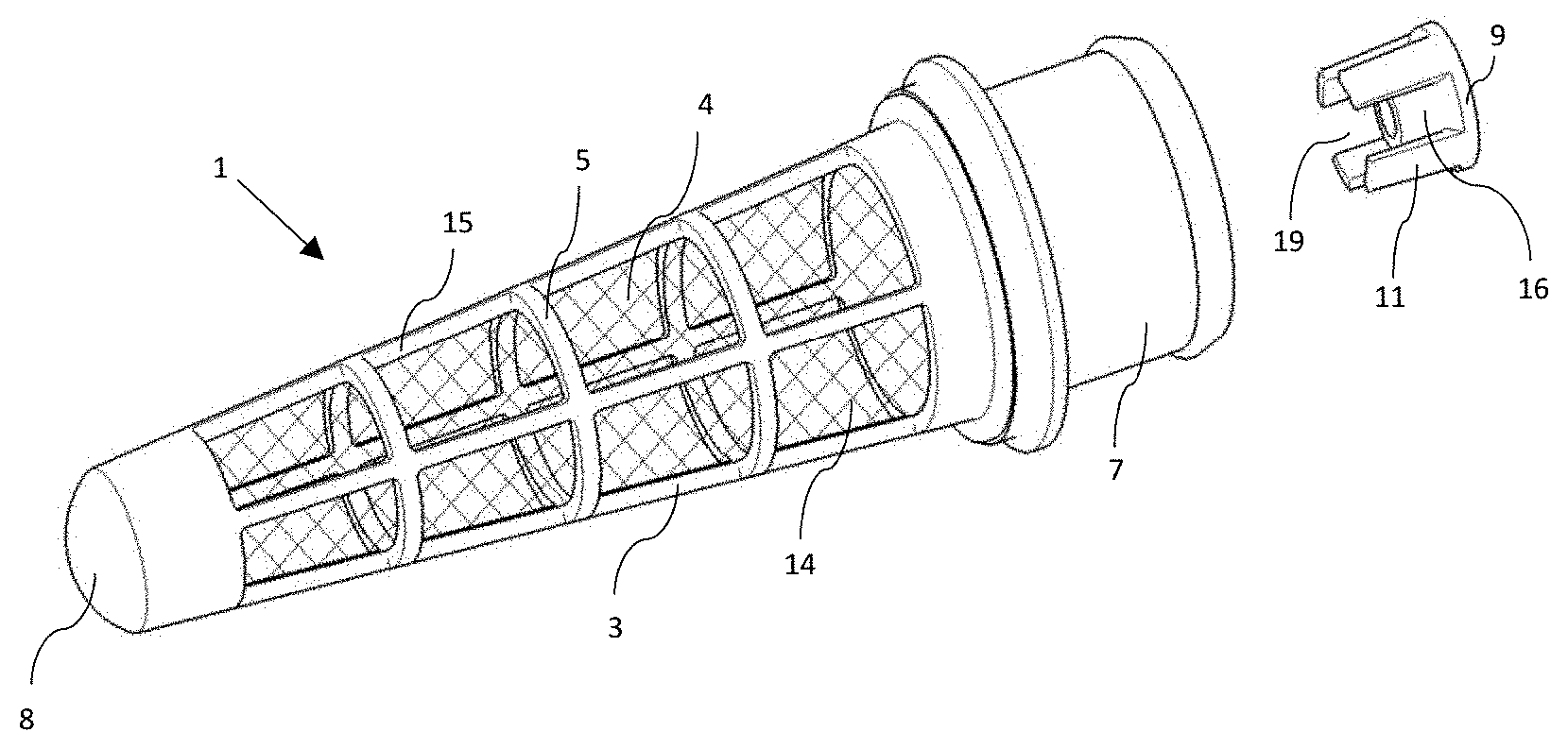
[0033] FIG. 3: a perspective view of the filter element with removed flow guidance;
[0034] FIG. 4: a perspective sectional view of the filter element with removed flow guidance;
[0035] FIG. 5: a perspective sectional view of the filter element with integrated flow guidance;
[0036] FIG. 6: a perspective sectional view of the flow guidance;
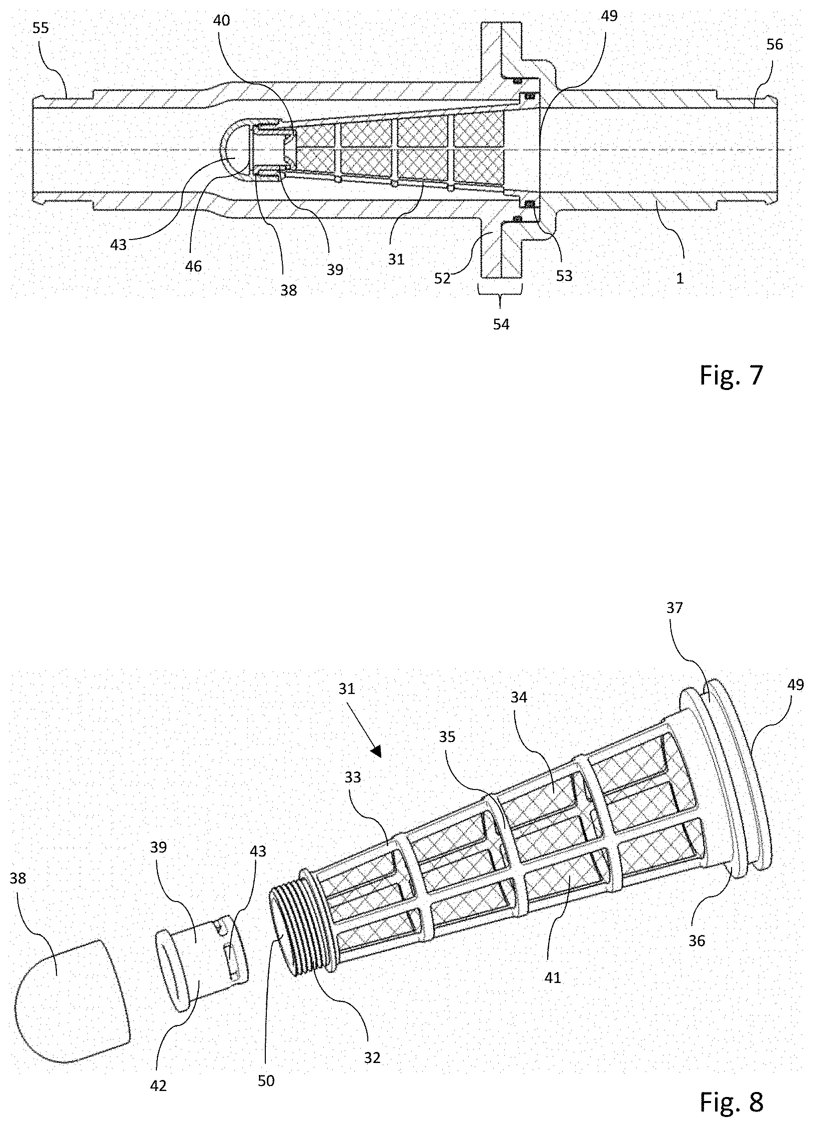
[0037] FIG. 7: a sectional view of a second variant of an embodiment of a filter element according to the invention; and
[0038] FIG. 8: a perspective view of the filter element of FIG. 7.
EMBODIMENT(S) OF THE INVENTION
[0039] FIG. 1 shows a cooling circuit 100 for cooling an electrochemical energy converter, preferably in the form of a fuel cell 102 or a stack of several fuel cells. Other electrochemical energy converters can also be cooled in this way. The structure of a fuel cell is known per se. It comprises an anode 104 and a cathode 105 separated by an electrolyte, e.g. a semi-permeable membrane. This semi-permeable membrane can be permeable to protons. Energy is generated by a reaction of hydrogen with oxygen.
[0040] The oxygen can be provided by an air inlet 111, e.g. as pure oxygen or as ambient air, or by a liquid medium, e.g. water. The oxygen or air can be moistened with water, for example, before it is fed into the fuel cell 102. To increase the humidity of the gas introduced, e.g. air or oxygen, the cooling circuit features a humidifier 103, which increases the air humidity before introducing it into the fuel cell 102.
[0041] In addition to the air inlet 111, the fuel cell 102 features also an inlet for fuel 106, in particular hydrogen. Furthermore, the fuel cell 102 features a supply line 114 for a coolant, e.g. deionized water. The supply line 111 is part of the cooling circuit 100.
[0042] The fuel cell 102 features also a discharge line 112 for exhaust gas or exhaust air and a discharge line 115 for the coolant from the fuel cell 102. The discharge line features a three-way valve 113. Depending on the circuit of the three-way valve 113, the coolant can be supplied to a heat exchanger 108 or to a bypass line 107 bypassing the heat exchanger 108. Furthermore, a cooling tank 109 can be provided on the discharge line 115 for the expansion of the coolant, which compensates for temperature-related pressure fluctuations of the coolant. A coolant pump 110 increases the coolant pressure before it is introduced into the fuel cell 102.
[0043] The above-mentioned example of an embodiment of a fuel cell 102 and an associated cooling circuit 100 is only to be understood as an example. A hydrocarbon such as alcohols, e.g. methanol or ethanol, can also be used as fuel instead of hydrogen.
[0044] A filter element 101, which filters out particulate impurities from the coolant, especially during commissioning or after refilling with coolant, is disposed on the supply line of the coolant to the fuel cell.
[0045] Current filter elements used for the application often include a filter medium for depth filtration allowing the dirt contained in the fluid to be filtered out of the coolant or coolant liquid. As a result, the dirt adheres firmly both inside and on the surface of the medium to the fibers located there and thus reduces the free cross-section of the medium above a certain amount of dirt, so that less flow cross-section is available for the volume flow and the pressure loss of the cooling medium due to the filter element increases over the course of time the filter element is in operation.
[0046] The filter element according to the invention, for example in the variants of an embodiment of FIGS. 2 to 6 and FIGS. 7 to 8, feature a clearly lower pressure loss over the operating time.
[0047] FIGS. 2 to 8 show a first variant of an embodiment of a filter element 1 according to the invention which is arranged in a pipe 2. Pipe 2 has a terminal protrusion 20 for connection to filter element 1. In addition, the pipe 2 features a pipe connection 21 for connecting the pipe 2 to a process line of a cooling circuit, e.g. the cooling circuit 100 of FIG. 1. The connection can be made, for example, by slipping a hose over it and then fastening it using hose clamps.
[0048] The filter element 1 features a grid support structure 3 with a cone-shaped course along its longitudinal axis A. The grid support structure 3 defines several grid windows 14 in which the filter medium 4 is disposed. The filter medium 4 is a screen mesh for separating particulate impurities in an interior space 10 of the filter element 1, which is limited by the grid support structure 3.
[0049] The grid support structure 3 features an end cap segment 8 closed to the exterior side of the filter element, which is an integral part of the grid support structure 3 in FIGS. 2 to 6. However, it is possible and advantageous to return the cooling medium towards the interior space 10.
[0050] The grid support structure 3 features annular struts 5, which extend transversely, in particular vertically, to the longitudinal axis A, and which decrease in ring diameter in the course of the longitudinal axis A towards the end cap segment 8. The annular struts 5 are connected to each other by longitudinal struts 15 and form a circumferential surface with a conical course.
[0051] Opposite the closed-wall end cap segment 8, the filter element 1 features at the end a union 7 with a supply opening 23 for connection to a process line of the aforementioned cooling circuit and for supplying coolant to filter element 1. This union 7 extends from an annular closed-wall pipe segment 22. This pipe segment 22 features an annular circumferential projection 6 to the stop and to the circumferential mould closure with the protrusion 20 of pipe 2. The projection 6 can be connected, e.g. by welding, to the protrusion 20 of the pipe 2 in a circumferential material-locking manner.
[0052] Between the end cap segment 8 and the pipe segment 22 are disposed the grid windows 14 with the filter medium 4. The end cap segment 8 features stop surfaces 12 for the stop of a flow guidance 9 inserted in the end cap segment 8.
[0053] This flow guidance 9 is shown in detail in FIG. 6. It can preferably be disposed detachably in the end cap segment 8. It features a funnel 16 with a funnel axis extending coaxially to the longitudinal axis A of the grid support structure. The funnel features a larger first funnel opening 17 and a smaller second funnel opening 18. The funnel 16 together with the end cap segment 8 defines a collecting chamber 13 to receive the filtered particulate impurities.
[0054] The larger funnel opening 17 is disposed in an inlet area of the end cap segment 8 and the smaller funnel opening 18 leads into the collecting chamber 13.
[0055] Support members 11, which extend parallel to the funnel axis at the edge of the funnel 16, relative to its radially outer circumferential edge, and which are preferably connected to the funnel 16 in a material-locking manner, are disposed on the funnel 16. In FIGS. 2 to 6, the support members 11 are designed as support feet spaced apart from each other. The gaps 19 between the support feet also serve as backflush openings for the medium to flow out of the collecting chamber 13 while the particles remain in the collecting chamber 13. The support members 11 rest on the stop surfaces 12.
[0056] The funnel serves as separation 16 between the collecting chamber 13 for particles or dirt and the actual filter medium 4. This funnel allows the particles arriving in the fluid to enter the collecting chamber in its funnel center and at the same time prevents the particles from being flushed back towards the filter medium 4.
[0057] FIGS. 7 and 8 feature a second variant of an embodiment of a filter element 31 according to the invention. It is clamped between two pipes 51 and 52, which are connected to each other via a flange connection 54. The flange connection 54 features a first sealing ring 53 for radial sealing. Terminally, i.e. at an opposite end to the flange connection 54, one pipe flange 55, 56 is disposed at each pipe 51, 52 for the connection to a process line.
[0058] The filter element 31 itself can be designed in three parts, comprising a grid support structure 33 with a longitudinal axis A with circumferential struts 35, which are connected to each other by longitudinal struts and define a circumferential surface as well as an interior space 41 enclosed by it. In the grid windows of the grid support structure or along the circumferential surface, a filter medium 34, in particular a screen mesh, is disposed.
[0059] Terminally, the grid support structure 33 features a closed-wall pipe segment 37 with an annular circumferential projection 36. This projection can feature an annular groove to accommodate a sealing ring for the radial seal, as shown in FIGS. 7 and 8.
[0060] The grid support structure 33 is terminally open on one side and features on the other side an interface 32 to an end cap 38, which is detachably disposed on the grid support structure 33. The interface 32 is in this case a screw thread. The end cap, in conjunction with the grid support structure 33, forms a collecting chamber 43 for particles.
[0061] Between the grid support structure 33 and the end cap 38 a flow guide component 39 is disposed, in particular clamped or screwed.
[0062] In analogy to FIGS. 2 to 6, this flow guidance also features a funnel 40, which enables dirt to be discharged towards the collecting chamber.
[0063] The grid support structure 33 features a supply opening 49 into the filter element 31 and a discharge opening at the transition to the flow guidance 39. Preferably, the diameter of the supply opening 49 is at least twice as large as the diameter of the discharge opening 50.
[0064] The funnel 40 features a circumferential cylindrical support member 42 at the edge, which can support itself on a stop surface 46 of the end cap 38 against axial displacement in the mounted state.
[0065] The support member 42 features return flow openings 43 at the edge, which serve to return the medium flowing in through the funnel 40, while the particles remain in the collecting chamber 43. Accordingly, the return flow openings 43 should be advantageously at least smaller than the inflow opening of the funnel 40.
[0066] In FIGS. 2 to 8, the funnel 16, 40 features an inwardly rounded shape, which has additional fluidic advantages.
[0067] The funnel 16, 40 shown in FIGS. 2 to 8 can, for example, feature an inlet diameter of 35-45 mm and an outlet diameter of 20-30 mm for the exit into the collecting chamber 13, 43. The inlet diameter is particularly preferably to be at least 20%, preferably at least 25% larger than the outlet diameter.
[0068] The internal diameter of the end cap or end cap segment can be between 40-50 mm. It is advantageously at least 30% larger than the outlet diameter.
[0069] The length of the filter element 1, 31 can preferably be between 100 mm and 230 mm, preferably between 130 mm and 200 mm.
[0070] The supply opening 49 into the filter element 31 and in analogy also the supply opening 23 for the filter element 1 can preferably feature a diameter between 14 and 20 mm, preferably between 15 and 18 mm.
[0071] The filter medium 4, 34 can be particularly preferably designed as screen mesh, preferably made of stainless steel, e.g. high-grade steel. The average mesh width of the filter medium, in particular of the screen mesh, can preferably be more than 70 .mu.m, in particular between 80 and 150 .mu.m, in particular between 100 and 120 .mu.m.
[0072] FIGS. 2 to 8 show only two preferred design variants of an embodiment. It is also conceivable that the funnel is part of the filter medium 4, 34, which can be inserted as a separate component of the filter element into the grid support structure.
[0073] The filter elements shown in FIGS. 2 to 8 each provide a collecting chamber 13, 43 for the dirt which is located outside the flow cross-section and thus does not restrict it. Thus, more dirt can be filtered out than with a conventional filter medium. An increase in pressure during operation does not occur or occurs only to a very small extent.
[0074] This means that a relatively large dirt capacity can be made available in a smaller installation space with relatively little filtration area. In addition, the mesh used as screen mesh without depth filtration offers an advantage in pressure loss for the high volume flows that can occur in a cooling circuit of an electrochemical energy converter, for example in the 250 l/min range.
[0075] The conical shape of the filter is also advantageous for the dirt particles. They slide along the mesh and then are flushed into the collecting chamber, in addition to the particles that have already reached it directly.
* * * * *
D00000
D00001
D00002
D00003
D00004
XML
uspto.report is an independent third-party trademark research tool that is not affiliated, endorsed, or sponsored by the United States Patent and Trademark Office (USPTO) or any other governmental organization. The information provided by uspto.report is based on publicly available data at the time of writing and is intended for informational purposes only.
While we strive to provide accurate and up-to-date information, we do not guarantee the accuracy, completeness, reliability, or suitability of the information displayed on this site. The use of this site is at your own risk. Any reliance you place on such information is therefore strictly at your own risk.
All official trademark data, including owner information, should be verified by visiting the official USPTO website at www.uspto.gov. This site is not intended to replace professional legal advice and should not be used as a substitute for consulting with a legal professional who is knowledgeable about trademark law.