Bathing Platform For A Bathtub
MALASSIGNE; Pascal ; et al.
U.S. patent application number 16/344603 was filed with the patent office on 2020-02-20 for bathing platform for a bathtub. This patent application is currently assigned to UNITED STATES GOVERNMENT as represented by THE DEPARTMENT OF VETERANS AFFAIRS. The applicant listed for this patent is UNITED STATES GOVERNMENT AS REPRESENTED BY THE DEPARTMENT OF VETERANS AFFAIRS, UNITED STATES GOVERNMENT AS REPRESENTED BY THE DEPARTMENT OF VETERANS AFFAIRS. Invention is credited to Kevin ALEXANDER, Mark CORS, Pascal MALASSIGNE.
| Application Number | 20200054176 16/344603 |
| Document ID | / |
| Family ID | 62025467 |
| Filed Date | 2020-02-20 |


View All Diagrams
| United States Patent Application | 20200054176 |
| Kind Code | A1 |
| MALASSIGNE; Pascal ; et al. | February 20, 2020 |
BATHING PLATFORM FOR A BATHTUB
Abstract
A bathing platform is provides that includes an elongated platform having a top surface and a bottom surface, a first long side, a second long side, a first short side and a second short side. A bottom surface portion of the first and second long sides is configured to engage an upper surface of the bathtub and support the elongated platform. A bottom surface portion of the first and second short sides may also engage with an upper surface of the bathtub and support the elongated platform.
| Inventors: | MALASSIGNE; Pascal; (Washington, DC) ; CORS; Mark; (Washington, DC) ; ALEXANDER; Kevin; (Washington, DC) | ||||||||||
| Applicant: |
|
||||||||||
|---|---|---|---|---|---|---|---|---|---|---|---|
| Assignee: | UNITED STATES GOVERNMENT as
represented by THE DEPARTMENT OF VETERANS AFFAIRS Washington DC |
||||||||||
| Family ID: | 62025467 | ||||||||||
| Appl. No.: | 16/344603 | ||||||||||
| Filed: | October 27, 2017 | ||||||||||
| PCT Filed: | October 27, 2017 | ||||||||||
| PCT NO: | PCT/US2017/058778 | ||||||||||
| 371 Date: | April 24, 2019 |
Related U.S. Patent Documents
| Application Number | Filing Date | Patent Number | ||
|---|---|---|---|---|
| 62413857 | Oct 27, 2016 | |||
| Current U.S. Class: | 1/1 |
| Current CPC Class: | A47K 3/125 20130101; A61G 7/0005 20130101 |
| International Class: | A47K 3/12 20060101 A47K003/12 |
Goverment Interests
GOVERNMENT RIGHTS
[0001] The U.S. Government has a paid-up license in this invention and the right in limited circumstances to require the patent owner to license others on reasonable terms as provided for by the terms of Grant No. F0627-R awarded by The Department of Veterans Affairs.
Claims
1. A bathing platform for a bathtub comprising: an elongated platform having a top surface and a bottom surface, a first long side, a second long side, a first short side and a second short side, a bottom surface portion of the first and second long sides configured to engage an upper surface of a bathtub and support the elongated platform; the elongated platform having a proximal section and a distal section separated by a middle section, wherein the proximal section comprises a first well configured to hold water and wherein the proximal section is positioned above a portion of the bathtub including the bathtub drain; the elongated platform further comprising a platform drain positioned at a low point in the first well of the proximal section, the platform drain configured to allow water to drain from the platform to the bathtub; wherein the distal section comprises a second well configured to hold water; wherein the middle section comprises a channel configured to allow water to flow from the second well to the first well.
2. The bathing platform of the claim 1, wherein a bottom surface portion of one or both of the first and second short sides is configured to engage an upper surface of the bathtub to support of the elongated platform.
3. The bathing platform of claim 1, wherein the first short side borders the distal end of the elongated platform, the elongated platform further comprising a backrest extending upward from the first short side.
4. The bathing platform of claim 1, wherein the elongated platform is symmetrical along a central axis parallel to the first and second long sides.
5. The bathing platform of claim 1, further comprising a drain tube connecting the platform drain to the bathtub drain.
6. The bathing platform of claim 1, wherein an upper surface of the first long edge comprises a rail configured to provide a transitional transfer surface positioned to facilitate transfer onto the top surface of the elongated platform.
7. The bathing platform of claim 1, further comprising a plurality of support ridges extending upward from the bottom surface of the platform toward the top surface of the platform.
8. The bathing platform of claim 7, wherein the middle section comprises a greater density of support ridges than the distal section.
9. The bathing platform of claim 7, wherein the distal section comprises a first plurality of support ridges between the central axis parallel to the first and second long sides and the first long side, wherein the platform drain is positioned on the central axis.
10. The bathing platform of claim 9, wherein the distal section comprises a second plurality of support ridges between the central axis and the second long side.
11. A bathing platform for a bathtub comprising: a support comprising at least two legs connected by at least one cross member, wherein a first leg of the support comprises one or more feet positioned inside a bathtub and wherein a second leg of the support comprises one or more feet positioned outside the bathtub and the at least one cross member is connected at a first end to the first leg and extends over the edge of the bathtub and is connected at a second end to the second leg; an elongated platform having a top surface and a bottom surface, a first long side, a second long side, a first short side and a second short side, wherein one or more bottom surface portions of the first long side, the second long side, the first short side and the second short side are configured to engage at least one of the at least one cross member to support the elongated platform; the elongated platform having a proximal section and a distal section separated by a middle section, wherein the proximal section comprises a first well configured to hold water and wherein the proximal section is positioned above a portion of the bathtub including the bathtub drain; the elongated platform further comprising a platform drain positioned at a low point in the first well of the proximal section, the platform drain configured to allow water to drain from the platform to the bathtub; wherein the distal section comprises a second well configured to hold water; wherein the middle section comprises a channel configured to allow water to flow from the second well to the first well.
12. The bathing platform of the claim 11, wherein one or more bottom surface portions of the first long side, the second long side, the first short side and the second short side is configured to engage an upper surface of the bathtub to support the elongated platform.
13. The bathing platform of claim 11, wherein the first short side borders the distal end of the elongated platform, the elongated platform further comprising a backrest extending upward from the first short side.
14. The bathing platform of claim 11, wherein the elongated platform is symmetrical along a central axis parallel to the first and second long sides.
15. The bathing platform of claim 11, further comprising a drain tube connecting the platform drain to the bathtub drain.
16. The bathing platform of claim 11, wherein an upper surface of the first long edge comprises a rail configured to provide a transitional transfer surface positioned to facilitate transfer onto the top surface of the elongated platform.
17. The bathing platform of claim 11, further comprising a plurality of support ridges extending upward from the bottom surface of the platform toward the top surface of the platform.
18. The bathing platform of claim 17, wherein the middle section comprises a greater density of support ridges than the distal section.
19. The bathing platform of claim 17, wherein the distal section comprises a first plurality of support ridges between the central axis parallel to the first and second long sides and the first long side, wherein the platform drain is positioned on the central axis.
20. The bathing platform of claim 19, wherein the distal section comprises a second plurality of support ridges between the central axis and the second long side.
Description
BACKGROUND
Field of the Invention
[0002] The present disclosure generally relates to bathing devices and more particular relates to a bathing platform that covers an installed bathtub.
Related Art
[0003] Lavatory devices that assist in bathing or showering are common among the elderly and disabled patient population. The National Center for Health Statistics has reported that about 10 percent of all people over the age of 65 have difficulty bathing, and about 6 percent receive help. In an assessment of home aids, adaptations and personal assistance received after traumatic spinal cord injury (SCI) in a population of 2.5 million inhabitants in Denmark, the most common aids or adaptations reported were related to the bathtub or shower (69%). Despite the increased awareness for bathroom assistance, no room at home poses more threats to safety than the bathroom. The National Safety Council reports that 7.8% of all injury episodes in the bathroom involved persons of age 65 or older. This is because the greatest danger in the bathroom is slipping and falling when entering and exiting the bathtub or shower.
[0004] To meet the needs of the aging population, the home health care services industry has grown from 40.8 million dollars in 2005 to 57.2 million dollars in 2009. Similar growth is predicted into the future based on the growing number of aging individuals entering retirement and desiring to stay within their homes. During this same period, the accessible bathtub and shower industry grew from 119.1 million dollars in 2005 to 148.5 million dollars in 2010. A similar growth rate was seen in the bath and pool lift industry that grew from 36.6 million dollars in 2005 to 45.6 million dollars in 2010. This growth rate of 4.5% per year is projected to continue as the boomers retire.
[0005] Individuals with spinal cord injury/dysfunction confront equivalent or even more significant challenges in the bathroom. The fixtures being developed by the design team will also serve this estimated population of 262,000 persons with SCID (National Spinal Cord Injury Statistics Center). There are approximately 12,000 new cases of spinal cord injury each year. Of these injuries, 51.9% are tetraplegia and 45.2% are paraplegia (National Spinal Cord Injury Statistics Center). This level of injury leads to diminished abilities and, in some cases, individuals will require caregiver assistance for bathing and other activities of daily life. The National Spinal Cord Injury Statistics Center (NSCISC) in Birmingham, Alabama, tracks over 91% of this population as living in private residences. The need to remain in the home is as compelling for a spinal cord injured patient as it is for the aging, prolonging independence, reducing health care costs and maintaining a high quality of life.
[0006] Therefore, what is needed is a system and method that overcomes these significant problems found in the conventional systems as described above.
SUMMARY
[0007] The present disclosure describes a bathing platform that covers a conventional bathtub as typically found in North America and can be placed equally over a right hand or a left hand bathtub. It is designed for use by ambulatory individuals that cannot sit at the bottom of a bathtub or individuals with spinal cord injury/dysfunctions who cannot transfer from their wheelchair to the bottom of a bathtub. The bathing platform is designed to rest on the front rim and the other three sides of standard size bathtubs within a home or a facility.
[0008] The present invention describes a novel bathing platform that can be placed equally over a right-hand or left-hand bathtub and designed for use by ambulatory and non-ambulattory individuals (e.g., elderly individuals and/or individuals with spinal cord injury ("SCI") or traumatic brain injury ("TBI")) who cannot transfer to and/or from the bottom of a normal bathtub. The bathing platform rests on two or more sides of standard size bathtubs and assists in the bathing of individuals within a home or facility. The bathing platform contains several features that assist users in transferring safely from a standing position or from a wheelchair onto the bathing platform. These features include a height similar to wheelchair height, and a higher rim. Additional features are incorporated in the design that facilitates an easy bathing process, including: a contoured backrest, a deep leg and feet soaking area, and a drain that connects to the main bathtub drain.
[0009] The proposed invention comprises two design features that distinguish the proposed invention from other similar technologies: 1) a symmetrical design that enables placement over at least a portion of the length and width of a right hand or left hand bathtub, 2) removability, which abolishes the requirement of permanent installation. The fact that the bathing platform can be removed and installed with minimal effort facilitates installation in the home and assisted-living facilities, especially compared with similar technologies that have to be more permanently installed.
[0010] The inventors have demonstrated proof-of-concept with a "mock" prototype composed of plywood. Using this mock design, the inventors tested the efficacy and safety of the bathing platform by allowing ten patients with paraplegia to sample the prototype. All of these volunteers lived independently and had documented history of transferring to bathing devices with minimal assistance. A universal response to the bathing platform was how sturdy it felt compared to shower benches and chairs. The sturdiness resulted in a relaxed confidence with the bathing platform across all volunteers and knowledge that it would not somehow fail them. The volunteers took a very similar approach by parking next to the bathing platform for a transfer. They all worked to get the front corner of their seat as close as possible to the bathing platform. One volunteer who struggled with this had swung his footrest to the side, which put it between his chair and the bathtub. Some volunteers did not touch the bathing platform as they aligned. Of all the volunteers, one used the vertical grab bar to assist with positioning his chair. All volunteers employed a "three-step process" while transferring to the bathing platform: 1) they aligned their chair, 2) they lifted themselves to the outside edge of the bathing platform and 3) they reset their hands for the final move onto the bathing platform. The wide outside rail was appreciated as a transition surface to sit on and change hand position while transferring. Once the volunteers moved out of their chairs and onto the wide edge of the bathtub, almost all of them stopped to reset their hands. At this point, several of the volunteers used the metal grab bar mounted on the wall as a support to lift themselves onto the bathing platform. Many of them kept their hands down low and used the raised edge at the back side of the bathing platform. Once inside the bathing platform, all of the volunteers described a feeling of being "safe and contained," with no fears of falling out of the unit. They also appreciated the strength of the backrest, which allowed them to lean back without fear of the backrest failing. Almost all of the volunteers suggested that padding be applied to the bathing platform to relieve pressure. A result of the raised foot position incorporated into the design was that it helped people access their feet for washing. The bathing platform raises the legs so they can lean forward to reach their feet without fear of falling off the seat. It also simplifies moving a foot up and into a crosslegged position, which facilitates foot washing. During shower simulation, the volunteers emphasized water management and avoiding splashing. The bathing platform kept many of the patients balanced so they did not have to hold onto anything. If they did hold on, they used the wall-mounted grab bar and more than the side rails to support themselves while washing. Transferring out and exiting the bathtub was the same "three-step process," except in reverse. The volunteers with the weakest abdomens had some struggles with the depth of the seat. This was a surprisingly high lift for some of them, and they had to drag their body up to the top of the rail to place their feet in the foot well.
[0011] Positioned over a bathtub the bathing platform is at wheelchair height to assist a user transferring safely and easily from a wheelchair. An ambulatory individual can also take advantage of the higher position of the rail to sit and transfer. Certain advantages of the bathing platform include that it is designed for ambulatory access or wheelchair level transfer, designed to be symmetrical for placement over a right hand or a left hand bathtub, designed to fit a variety of standard bathtub widths, designed with a contoured backrest, designed with a deep leg and foot well for soaking, and designed to drain in the main bathtub drain.
[0012] Other features and advantages of the present invention will become more readily apparent to those of ordinary skill in the art after reviewing the following detailed description and accompanying drawings.
BRIEF DESCRIPTION OF THE DRAWINGS
[0013] The structure and operation of the present invention will be understood from a review of the following detailed description and the accompanying drawings in which like reference numerals refer to like parts and in which:
[0014] FIG. 1A is a perspective view diagram illustrating an example bathing platform for a left hand bathtub according to an embodiment of the invention;
[0015] FIG. 1B is a perspective view diagram illustrating an example bathing platform for a right hand bathtub according to an embodiment of the invention;
[0016] FIG. 2 is a cross sectional view diagram illustrating an example bathing platform for a left hand bathtub according to an embodiment of the invention;
[0017] FIG. 3 is a side view diagram illustrating an example bathing platform according to an embodiment of the invention;
[0018] FIG. 4 is a top view diagram illustrating an example bathing platform according to an embodiment of the invention;
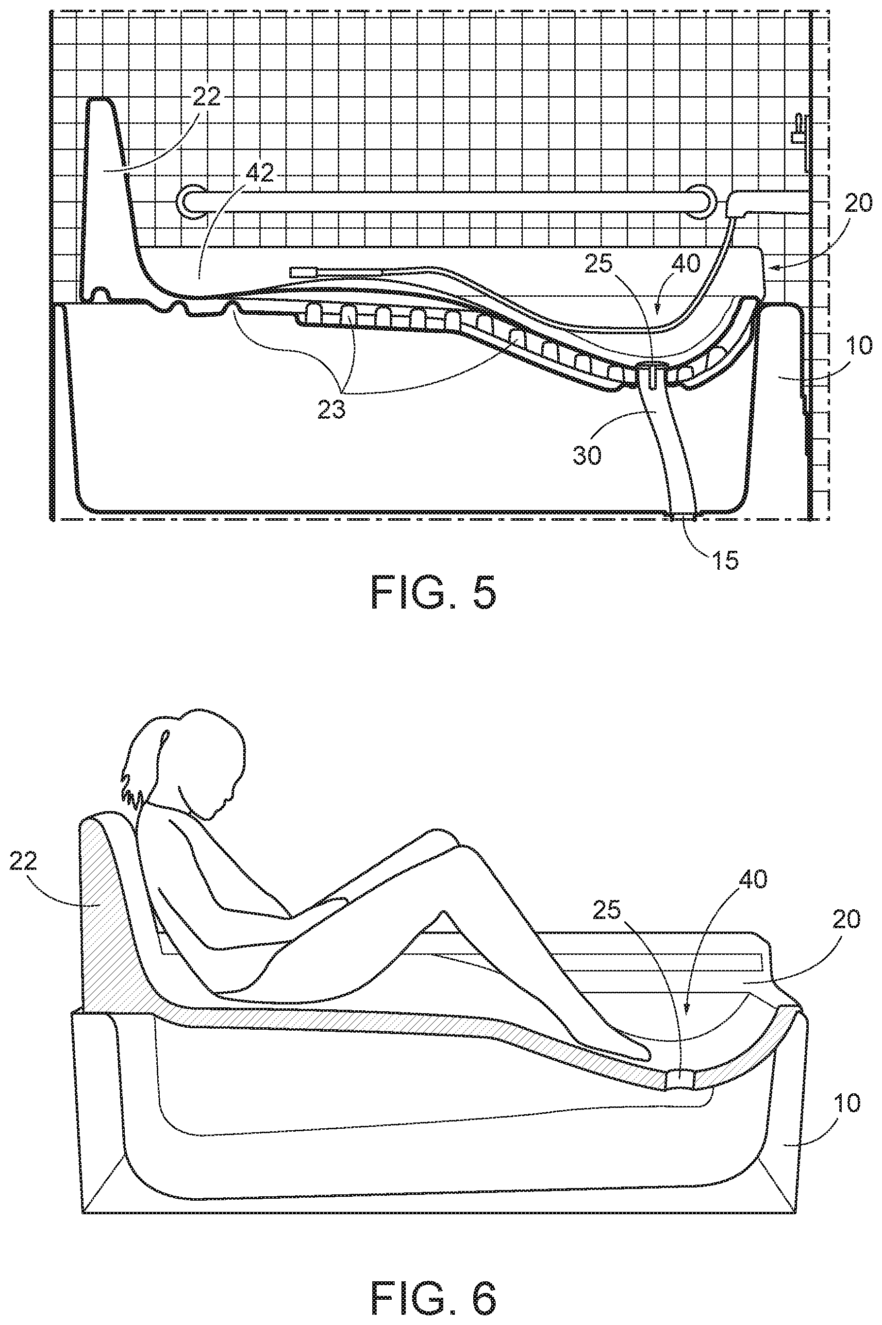
[0019] FIG. 5 is a side view diagram illustrating an example cross section of a bathing platform according to an embodiment of the invention;
[0020] FIG. 6 is a side view diagram illustrating an example cross section of a bathing platform with a bather according to an embodiment of the invention;
[0021] FIG. 7 is a perspective view diagram illustrating an example of ambulatory access to a bathing platform according to a previous embodiment of the invention;
[0022] FIG. 8 is a perspective view diagram illustrating an example of a wheelchair transfer to the bathing platform according to a previous embodiment of the invention;
[0023] FIG. 9 is a perspective view diagram illustrating an example of a wheelchair transfer to the bathing platform according to a previous embodiment of the invention;
[0024] FIGS. 10A-10C are perspective view diagrams illustrating an example bathtub and bathing platform with a support according to an embodiment of the invention;
[0025] FIGS. 11A-11C are cross section diagrams illustrating the example bathing platform with a support of FIGS. 10A-10C according to an embodiment of the invention;
[0026] FIGS. 12A-12C are perspective view diagrams illustrating an example bathtub and bathing platform with a support according to an embodiment of the invention;
[0027] FIGS. 13A-13C are cross section diagrams illustrating the example bathing platform with a support of FIGS. 12A-12C according to an embodiment of the invention;
[0028] FIGS. 14A-14C are perspective view diagrams illustrating an example bathtub and bathing platform with a support according to an embodiment of the invention;
[0029] FIGS. 15A-15C are cross section diagrams illustrating the example bathing platform with a support of FIGS. 14A-14C according to an embodiment of the invention;
[0030] FIGS. 16A-16C are perspective view diagrams illustrating an example bathtub and bathing platform with a support according to an embodiment of the invention;
[0031] FIGS. 17A-17C are cross section diagrams illustrating the example bathing platform with a support of FIGS. 16A-16C according to an embodiment of the invention;
[0032] FIGS. 18A-18C are perspective view diagrams illustrating an example bathtub and bathing platform with a support according to an embodiment of the invention;
[0033] FIGS. 19A-19C are cross section diagrams illustrating the example bathing platform with a support of FIGS. 17A-17C according to an embodiment of the invention;
[0034] FIG. 20A is a top view diagram illustrating example dimensions for standard bathtubs on which a bathing platform can be mounted according to an embodiment of the invention;
[0035] FIG. 20B is a side view diagram illustrating example dimensions for standard bathtubs on which a bathing platform can be mounted according to an embodiment of the invention.
DETAILED DESCRIPTION
[0036] Certain embodiments disclosed herein provide for a bathing platform configured to cover a conventional bathtub that facilitates reduced injury access to existing bathing facilities and provides simplified transfer from a wheelchair to use the bathing facilities. For example, one embodiment disclosed herein includes a bathing platform that rests on the upper surface edges of an existing bathtub and provides a bathing platform with a soaking well for the user while also taking advantage of existing bathing facilities such as plumbing for bathing water and drainage. After reading this description it will become apparent to one skilled in the art how to implement the invention in various alternative embodiments and alternative applications. However, although various embodiments of the present invention will be described herein, it is understood that these embodiments are presented by way of example only, and not limitation. As such, this detailed description of various alternative embodiments should not be construed to limit the scope or breadth of the present invention as set forth in the appended claims.
[0037] FIG. 1A is a perspective view diagram illustrating an example bathing platform 20 for a left hand bathtub 10 according to an embodiment of the invention. In the illustrated embodiment, the bathing platform 20 comprises an elongated platform having a top surface and a bottom surface and a backrest 22, a first long side having an upper rail surface 24, a second long side having an upper rail surface 24, a first short side and a second short side. Advantageously, a bottom surface portion of each of the first and second long sides is configured to engage an upper surface of the bathtub 10 and support the elongated platform. In alternative embodiments, a bottom surface portion of one or both of the first and second short sides is configured to engage an upper surface of the bathtub 10 for additional support of the elongated platform.
[0038] FIG. 1B is a perspective view diagram illustrating an example bathing platform 20 for a right hand bathtub 10 according to an embodiment of the invention. In the illustrated embodiment, the bathing platform 20 comprises an elongated platform having a top surface and a bottom surface and a backrest 22, a first long side having an upper rail surface 24, a second long side having an upper rail surface 24, a first short side and a second short side. As previously discussed, a bottom surface portion of each of the first and second long sides and one or both of the first and second short sides is configured to engage an upper surface of the bathtub 10 and collectively support the elongated platform.
[0039] FIG. 2 is a cross sectional diagram illustrating an example bathing platform 20 for a left hand bathtub 10 according to an embodiment of the invention. In the illustrated embodiment, the bottom surface of each of the first and second long sides are engaged with an upper surface of the bathtub 10 and the top surface 24 of each of the first and second long sides forms a wide rail configured to support a user when transferring onto or of of the platform 20. In the illustrated embodiment, the platform 20 also includes a backrest 22.
[0040] FIG. 3 is a side view diagram illustrating an example bathing platform 20 placed on a cross section of a bathtub 10 according to an embodiment of the invention. In the illustrated embodiment, the bathing platform comprises an elongated platform 20 having a top surface and a bottom surface, a first long side, a second long side, a first short side and a second short side. A bottom surface portion of the first and second long sides is configured to engage an upper surface of the bathtub 10 and support the elongated platform 20. The engagement of the bottom surface portion of the first and second long sides with an upper surface of a bathtub 10 is not shown due to the cross sectional view. However, the illustration does show the engagement of a bottom surface portion of the first and second short sides with an upper surface of the bathtub 10. Advantageously, the elongated platform 20 may be configured such that a bottom surface of at least two of the first long side, second long side, first short side and second short side engage an upper surface of the bathtub 10 and thereby support the elongated platform 20 above the bathtub 10.
[0041] In the illustrated embodiment, the elongated platform 20 includes a proximal section and a distal section separated by a middle section, wherein the proximal section comprises a first well 40 configured to hold water and wherein the proximal section is positioned above a portion of the bathtub 10 including the bathtub drain 15. Additionally, the elongated platform 20 also comprises a platform drain 25 positioned at a low point in the first well 40 of the proximal section, the platform drain 25 configured to allow water to drain from the elongated platform 20 to the bathtub 10.
[0042] Furthermore, in the illustrated embodiment the distal section of the elongated platform 20 comprises a second well 42 that is also configured to support a bather and hold water. The elongated platform 20 also comprises a channel 50 that is configured to allow water to flow from the second well 42 to the first well 40.
[0043] Also in the illustrated embodiment, the first short side of the elongated platform 20 borders the distal section of the elongated platform 20 and the elongated platform 20 includes a backrest 22 extending upward from the first short side. Advantageously, in various embodiments the elongated platform 20 is symmetrical along a central axis parallel to the first and second long sides so it can be positioned over a convention bathtub that is either left handed or right handed.
[0044] FIG. 4 is a top view diagram illustrating an example bathing platform 20 according to an embodiment of the invention. In the illustrated embodiment, the bathing platform 20 comprises a backrest 22 and two rails 24 formed by an upper surface of each long edge of the platform 20. The platform 20 also comprises a second well 42 connected to a first well 40 by a channel 50. At a low point in the first well 40 is a platform drain 25 that is configured to allow water to drain out from the first well 40 of the platform 20 and into the bathtub 10.
[0045] FIG. 5 is a side view diagram illustrating an example cross section of a bathing platform 20 according to an embodiment of the invention. In the illustrated embodiment, the bathing platform 20 comprises second well 42 and a first well 40 that are connected by a channel 50 such that fluid can flow from the second well 42 into the first well 40. The platform 20 also includes a plurality of support ridges 23 configured to increase the stability and load bearing capability of the platform 20. Also shown in the illustrated embodiment is a drain tube 30 connecting the platform drain 25 to the bathtub drain 15. The drain tube 30 advantageously reduces or eliminates the need to clean the surface of the bathtub 10 beneath the platform 20 because the bathing water from the bathing platform 20 drains directly form the platform 20 to the bathtub drain 15.
[0046] FIG. 6 is a side view diagram illustrating an example cross section of a bathing platform 20 according to an embodiment of the invention. In the illustrated embodiment, a user is shown sitting on the bathing platform 20 and resting against the backrest 22. The feet of the user are in the well 40 near the platform drain 25, which extends through a lower surface of the platform 20 in the well 40.
[0047] FIG. 7 is a perspective view diagram illustrating an example of ambulatory access to the bathing platform 20 according to a previous embodiment of the invention. In the illustrated embodiment, a user employs the surface of the rail 24 to position the user's body for transfer from a position on the floor near the bathtub 10 to a position on the bathing platform 20. The user may also hold onto a rail 26 during the transfer from the floor to the platform 20.
[0048] FIG. 8 is a perspective view diagram illustrating an example of a wheelchair transfer to the bathing platform 20 according to a previous embodiment of the invention. In the illustrated embodiment, the user positions the wheelchair near the bathtub 10 and bathing platform 20. The user may grasp the backrest 22 or a handle 26 when transferring form the wheelchair onto the platform 20. The height and width of the wide rail 24 of the platform 20 provides a transitional surface that the user can employ to facilitate transfer from the wheelchair to the bathing platform 20. A channel 50 facilitates the flow of water from the second well 42 into the first well 40 so that the water can drain from the bottom of the first well 40 into the bathtub 10.
[0049] FIG. 9 is a perspective view diagram illustrating an example of a wheelchair transfer to the bathing platform 20 according to a previous embodiment of the invention. In the illustrated embodiment, the user positions the wheelchair near the bathtub 10 and bathing platform 20. The user may grasp the backrest 22 or a handle 26 when transferring form the wheelchair onto the platform 20. The height and width of the wide rail 24 of the platform 20 provides a transitional surface that the user can employ to facilitate transfer from the wheelchair to the bathing platform 20. Advantageously, the height of the upper surface of the rail 24 is configured to be substantially level with the height of the surface of a seat of the wheelchair.
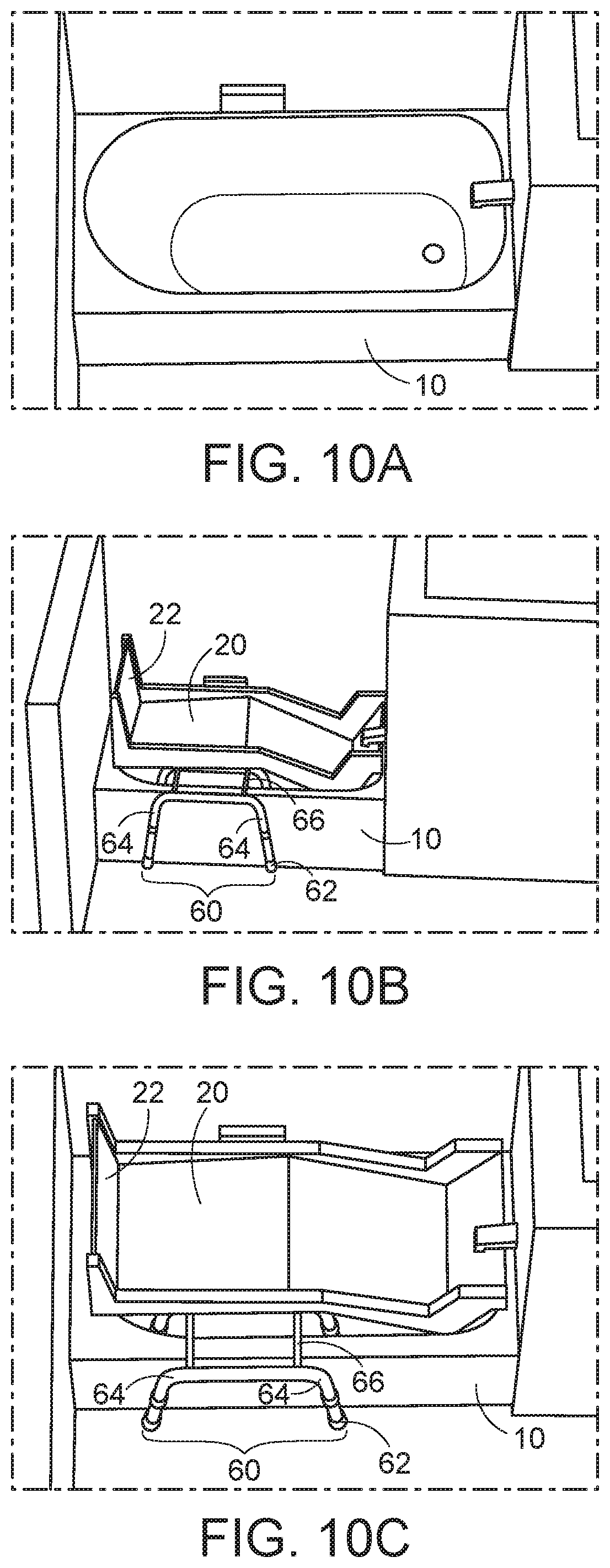
[0050] FIGS. 10A-10C are perspective view diagrams illustrating an example bathtub 10 and bathing platform 20 with a support 60 according to an embodiment of the invention. In the illustrated embodiment, the bathing platform 20 is positioned above a conventional bathtub 10. The bathing platform 20 is partially supported by the bathtub 10 and by a support 60. The support 60 comprises two or more legs 64 that are connected to each other by one or more cross members 66. Each leg 64 has two or more feet 62.
[0051] In the illustrated embodiment, the support 60 comprises three legs 64 connected to each other by two cross members 66. Each leg 64 includes two feet 62. The first and second legs 64 of the support 60 are positioned inside the bathtub 10 and the third leg 64 is positioned outside the bathtub 10. Two cross members 66 are each connected at a first end to the first leg 64, at a middle portion to the second leg 64 and at a second end to the third leg 64. The cross members 66 each extend over the edge of the bathtub 10 between the second leg 64 and the third leg 64.
[0052] As previously discussed, the elongated platform 20 has a top surface and a bottom surface, a first long side, a second long side, a first short side and a second short side. However, in the illustrated embodiment, the upper surface of the edge of the bathtub 10 is left exposed and available for the user to access during transfer to the bathing platform 20.
[0053] Accordingly, one or more bottom surface portions of the first long side, the second long side, the first short side and the second short side are configured to engage one or more of the cross members 66 and/or an upper surface of the bathtub 10 to support the elongated platform 20. For example, the long side of the platform 20 that is adjacent to the user transfer approach side of the bathtub 10 is configured to engage the cross members 66 while the long side of the platform 20 that is furthest away from the user transfer approach side of the bathtub 10 may be configured to engage an upper surface of the bathtub 10 to support the elongated platform 20. Alternatively the long side of the platform 20 that is furthest away from the user transfer approach side of the bathtub 10 may be configured not to engage an upper surface of the bathtub 10 to support the elongated platform 20 such that the elongated platform 20 is primarily supported by the support 60.
[0054] Additionally in the illustrated embodiment, the elongated platform 20 has a proximal section and a distal section separated by a middle section, wherein the proximal section comprises a first well configured to hold water and wherein the proximal section is positioned above a portion of the bathtub 10 including the bathtub drain. Advantageously, the distal and middle sections are sloped to allow water to collect in the first well and drain out to the bathtub 10 as previously described. In one embodiment, the distal section may include a second well and the middle section may include a channel that allows water to flow from the distal well to the proximal well.
[0055] Moreover, in the illustrated embodiment, the bathing platform 20 includes a backrest to support the user in an upright position while using the bathing platform 20. The backrest extends upward from one of the short sides of the platform 20. Advantageously, the platform 20 is configured to be symmetrical along a central axis parallel to the first and second long sides. This symmetry allows the platform 20 to be positioned over a right hand bathtub or a left hand bathtub. Another advantage of the platform 20 is that it can be positioned for use with a first bathtub and then moved and positioned for use with a second bathtub, thereby eliminating semi-permanent installation of the bathing platform 20. Although not shown, the platform 20 may also include a drain tube connecting the platform drain to the bathtub drain.
[0056] FIGS. 11A-11C are cross section diagrams illustrating the example bathing platform 20 with a support 60 of FIGS. 10A-10C according to an embodiment of the invention. In the illustrated embodiment, referring specifically to the cross section in FIG. 11C, the three legs 64 are shown and one cross member 66 is shown connecting a portion of the first leg 64 to a portion of the second leg 64. Also, in FIGS. 11A and 11B, certain interference areas 70 are illustrated. The interference areas 70 are areas where a portion of the bathing platform 20 would undesirably engage a portion of the inner surface of the bathtub 10 or a portion of the bathing facilities such as a water spout. Accordingly, along the interference areas 70, the bathing platform 20 is configured with one or more recesses to prevent engagement of the platform 20 with a portion of the inner surface of the bathtub 10 or with a portion of any bathing facilities at one or more interference areas 70. Advantageously, preventing engagement of the bathing platform 20 with the surface of the bathtub 10 at the interference areas 70 allows the bathing platform 20 to be fully and properly supported along the short sides and the long sides of the platform 20 that engage an upper surface of the bathtub 10 and also along the cross members 66 of the support 60.
[0057] FIGS. 12A-12C are perspective view diagrams illustrating an example bathtub and bathing platform 20 with a support 60 according to an embodiment of the invention. In the illustrated embodiment, the bathing platform 20 is adapted to a different size and shape and orientation of a conventional bathtub 10.
[0058] FIGS. 13A-13C are cross section diagrams illustrating the example bathing platform 20 with a support 60 of FIGS. 12A-12C according to an embodiment of the invention. In the illustrated embodiment, the platform 20 is configured with one or more recesses to prevent engagement of the platform 20 with a portion of the inner surface of the bathtub 10 or with a portion of any bathing facilities at one or more interference areas 70.
[0059] FIGS. 14A-14C are perspective view diagrams illustrating an example bathtub and bathing platform 20 with a support 60 according to an embodiment of the invention. In the illustrated embodiment, the bathing platform 20 is adapted to a different size and shape and orientation of a conventional bathtub 10.
[0060] FIGS. 15A-15C are cross section diagrams illustrating the example bathing platform 20 with a support 60 of FIGS. 14A-14C according to an embodiment of the invention. In the illustrated embodiment, the platform 20 is configured with one or more recesses to prevent engagement of the platform 20 with a portion of the inner surface of the bathtub 10 or with a portion of any bathing facilities at one or more interference areas 70.
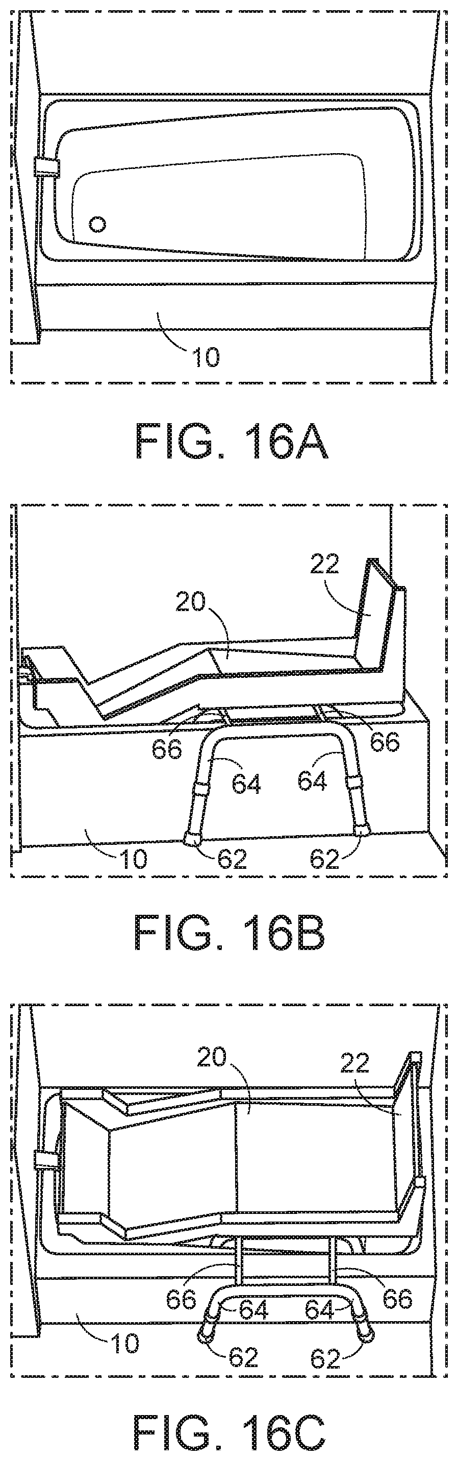
[0061] FIGS. 16A-16C are perspective view diagrams illustrating an example bathtub and bathing platform 20 with a support 60 according to an embodiment of the invention. In the illustrated embodiment, the bathing platform 20 is adapted to a different size and shape and orientation of a conventional bathtub 10.
[0062] FIGS. 17A-17C are cross section diagrams illustrating the example bathing platform with a support of FIGS. 16A-16C according to an embodiment of the invention.
[0063] FIGS. 18A-18C are perspective view diagrams illustrating an example bathtub and bathing platform 20 with a support 60 according to an embodiment of the invention. In the illustrated embodiment, the bathing platform 20 is adapted to a different size and shape and orientation of a conventional bathtub 10.
[0064] FIGS. 19A-19C are cross section diagrams illustrating the example bathing platform with a support of FIGS. 18A-18C according to an embodiment of the invention. In the illustrated embodiment, the platform 20 fits within the standard dimensions of the conventional bathtub 10 and does not undesirably engage any portion of any bathing facilities.
[0065] FIG. 20A is a top view diagram illustrating example dimensions for a standard bathtub 10 on which a bathing platform can be mounted according to an embodiment of the invention.
[0066] FIG. 20B is a side view diagram illustrating example dimensions for a standard bathtub 10 on which a bathing platform can be mounted according to an embodiment of the invention.
[0067] Those of skill in the art will appreciate that the various illustrative blocks, features and elements described in connection with the figures and the embodiments disclosed herein can often be implemented using alternative materials and alternative shapes that carry out the same functions described herein. To clearly illustrate this interchangeability, various illustrative components, blocks, features, and steps have been described above generally in terms of their functionality. Whether such functionality is implemented precisely as described above depends upon the particular application and design constraints imposed on the overall system. Skilled persons can implement the described functionality in varying ways for each particular application, but such implementation decisions should not be interpreted as a departure from the scope of the invention. In addition, the grouping of functions within a particular module, block, or step is for ease of description. Specific functions or steps can be moved from one module, block or step to another without departing from the scope of the invention.
[0068] The above description of the disclosed embodiments is provided to enable any person skilled in the art to make or use the invention. Various modifications to these embodiments will be readily apparent to those skilled in the art, and the generic principles described herein can be applied to other embodiments without departing from the spirit or scope of the invention. Thus, it is to be understood that the description and drawings presented herein represent a presently preferred embodiment of the invention and are therefore representative of the subject matter which is broadly contemplated by the present invention. It is further understood that the scope of the present invention fully encompasses other embodiments that may become obvious to those skilled in the art and that the scope of the present invention is accordingly not limited.
* * * * *
D00000
D00001
D00002
D00003
D00004
D00005
D00006
D00007
D00008
D00009
D00010
D00011
D00012

D00013

D00014

XML
uspto.report is an independent third-party trademark research tool that is not affiliated, endorsed, or sponsored by the United States Patent and Trademark Office (USPTO) or any other governmental organization. The information provided by uspto.report is based on publicly available data at the time of writing and is intended for informational purposes only.
While we strive to provide accurate and up-to-date information, we do not guarantee the accuracy, completeness, reliability, or suitability of the information displayed on this site. The use of this site is at your own risk. Any reliance you place on such information is therefore strictly at your own risk.
All official trademark data, including owner information, should be verified by visiting the official USPTO website at www.uspto.gov. This site is not intended to replace professional legal advice and should not be used as a substitute for consulting with a legal professional who is knowledgeable about trademark law.