Automatic Beverage Maker Reservoir Heating System
Moon; Jung S. ; et al.
U.S. patent application number 16/553288 was filed with the patent office on 2020-02-20 for automatic beverage maker reservoir heating system. The applicant listed for this patent is NuWave, LLC. Invention is credited to Jian Jiang Liu, Jung S. Moon.
| Application Number | 20200054164 16/553288 |
| Document ID | / |
| Family ID | 69523192 |
| Filed Date | 2020-02-20 |


| United States Patent Application | 20200054164 |
| Kind Code | A1 |
| Moon; Jung S. ; et al. | February 20, 2020 |
Automatic Beverage Maker Reservoir Heating System
Abstract
An automatic beverage maker having a water supply, a housing having a base, a body and a pod section, a sealed water tank within the housing body, a heating system for controlling the heating of water contained within the water tank, a first water line connecting the water supply to the water tank inlet, a second water e connecting the water outlet to the cavity of the housing pod section, a water pump for moving water from the water supply to the tank via the first water line and from the tank to the cavity of the housing pod section via the second water line. A drain line fluidly coupled to the sealed tank and having an open end for discharging water from the sealed water tank may also be used.
| Inventors: | Moon; Jung S.; (Long Grove, IL) ; Liu; Jian Jiang; (Jiangmen City, CN) | ||||||||||
| Applicant: |
|
||||||||||
|---|---|---|---|---|---|---|---|---|---|---|---|
| Family ID: | 69523192 | ||||||||||
| Appl. No.: | 16/553288 | ||||||||||
| Filed: | August 28, 2019 |
Related U.S. Patent Documents
| Application Number | Filing Date | Patent Number | ||
|---|---|---|---|---|
| 16296519 | Mar 8, 2019 | |||
| 16553288 | ||||
| 15916818 | Mar 9, 2018 | |||
| 16296519 | ||||
| 15867012 | Jan 10, 2018 | |||
| 15916818 | ||||
| 62444453 | Jan 10, 2017 | |||
| Current U.S. Class: | 1/1 |
| Current CPC Class: | A47J 31/461 20180801; A47J 31/469 20180801; A47J 31/0673 20130101; A47J 31/057 20130101; A47J 31/56 20130101; A47J 31/5253 20180801 |
| International Class: | A47J 31/52 20060101 A47J031/52; A47J 31/057 20060101 A47J031/057; A47J 31/06 20060101 A47J031/06; A47J 31/46 20060101 A47J031/46 |
Claims
1. An automatic beverage maker comprising: a water supply suitable for use in making a beverage; a housing having a base, a body and a pod-retention module, wherein the pod-retention module comprises a cavity for placement of a beverage pod to be used in making a beverage and a delivery opening for dispensing the beverage; a sealed water tank within the housing body, and having a water inlet and a water outlet; a heating system comprising: a heating element contacting an outer surface of the sealed water tank for heating water contained within the water tank; a temperature probe positioned within the sealed water tank such that the probe is at least partially submerged when the tank is filled with water; a first temperature sensor positioned within and proximate an end of the probe; a second temperature sensor positioned within the probe and spaced a distance from the first temperature probe; and a controller for activating the heating element in response to a threshold temperature sensed by at least one of the first temperature sensor and the second temperature sensor; a first water line connecting the water supply to the water inlet of the sealed tank; a second water line connecting the water outlet to the pod-retention module; and a water pump for moving water from the water supply to the sealed tank through the first water line and from the tank to the pod-retention module through the second water line.
2. The automatic beverage maker of claim 1, wherein the first temperature sensor and the second temperature sensor each comprises a negative temperature coefficient (NTC) thermistor.
3. The automatic beverage maker of claim 1, further comprising a drain line fluidly coupled to the sealed tank and having an open end for discharging water from the sealed water tank.
4. The automatic beverage maker of claim 1, wherein the sealed tank further comprises an air inlet to facilitate draining of the tank.
5. The automatic beverage maker of claim 3, wherein the sealed tank further comprises an air inlet to facilitate draining of the tank.
6. The automatic beverage maker of claim 5, wherein the air inlet connects to the sealed tank proximate a top of the tank and the drain line connects to the sealed tank through the first water line.
7. The automatic beverage maker of claim 3, further comprising a drain line valve cover to prevent discharge of water from the sealed tank.
8. The automatic beverage maker of claim 7, further comprising an air inlet line valve cover.
9. The automatic beverage maker of claim 8, wherein the drain line valve cover and the air inlet valve cover comprise a single valve cover.
10. The automatic beverage maker of claim 3, wherein the first water line and the drain line connect to the water inlet via a three-way valve.
11. The automatic beverage maker of claim 9, wherein the drain line and the air inlet each have an open end in the housing base.
12. The automatic beverage maker of claim 1, further comprising a drain valve cover detachable from the housing base.
13. The automatic beverage maker of claim 1, wherein the controller activates the heating element to maintain water within the tank at a first threshold temperature (T.sub.1) as measured by the first temperature sensor.
14. The automatic beverage maker of claim 13, wherein the controller activates the heating element to maintain water within the tank at a second threshold temperature (T.sub.2) as measured by the second temperature sensor.
15. The automatic beverage maker of claim 13, wherein the first threshold temperature (T.sub.1) is a brewing temperature.
16. The automatic beverage maker of claim 14, wherein the second threshold temperature (T.sub.2) is a preheating temperature.
17. The automatic beverage maker of claim 14, wherein the first temperature threshold (T.sub.1) is lower than the second temperature threshold (T.sub.2).
Description
RELATED APPLICATIONS
[0001] The present application is a continuation-in-part of, and claims priority to U.S. patent application Ser. No. 16/296,519, titled "Automatic Beverage Maker Reservoir With Drain" filed on Mar. 8, 2019, which claims priority of U.S. patent application Ser. No. 15/916,818, titled "Automatic Beverage Maker" filed on Mar. 9, 2018, which is a continuation-in-part of U.S. patent application Ser. No. 15/867,012, titled "Automatic Beverage Maker" filed Jan. 10, 2018. The '519, '818 and '012 applications are incorporated herein by reference in their entirety.
TECHNICAL FIELD OF THE INVENTION
[0002] The present invention relates to automatic beverage makers. More specifically, the invention relates to a more accurate and safe heating system for an automatic beverage maker.
BACKGROUND OF THE INVENTION
[0003] Coffee has become an essential part of modern life. Some people can hardly function without their morning brew. Single-serving coffee makers (aka, pod brews) are popular home coffee makers because they can brew single cups of gourmet coffee in just a few seconds. But in order to keep the coffee tasting great, it is important to achieve the proper water temperature for brewing.
[0004] In fact, studies show that the optimal temperature for brewing coffee, tea, and hot cocoa is 192.degree. F. This target is for the internal temperature of the water in the beverage machine/brewer hot-water tank/reservoir. The actual temperature of the brewed coffee, tea, or hot cocoa being dispensed is lower and can vary greatly based on cup temperature and cup material. Accordingly, the tank water temperature is critical to achieving the best brew possible.
[0005] One problem in achieving this optimal temperature is due, in part, to the inability to accurately sense the temperature of water in the hot-water tank. A temperature sensor inserted within the reservoir determines the temperature at the reservoir bottom. However, the hottest water will be at the top of the reservoir. For this reason, the water at the top may exceed the optimal temperature and cause a significant and potentially dangerous pressure increase within the sealed hot-water tank.
[0006] Further, prior brewing systems have only a single set temperature--preferably one which is at or near the temperature for optimal brewing. However, some people prefer a cooler brew, while others prefer hotter. Accordingly, these individuals are required to alter the final product in some manner--e.g., microwaving, adding ice, etc. These steps can negatively impact the flavor of the brewed beverage.
[0007] Until the invention of the present application, these and other problems in the prior art went either unnoticed or unsolved by those skilled in the art. The present invention provides a hot-water tank for a beverage maker which provides greater certainty as to the brewing temperature and provides options for raising and lowering the brewing temperature, all without sacrificing design, style or affordability.
SUMMARY OF THE INVENTION
[0008] There is disclosed herein an improved beverage maker which avoids the disadvantages of prior devices while affording additional structural and operating advantages.
[0009] Generally speaking, the automatic beverage maker comprises a water supply suitable for use in making a beverage, a housing having a base, a body and a pod-retention module, wherein the pod-retention module comprises a cavity for placement of a beverage pod to be used in making a beverage and a delivery opening for dispensing the beverage, a sealed water tank within the housing body, and having a water inlet and a water outlet, and a heating system. The preferred heating system comprises a heating element contacting an outer surface of the sealed water tank for heating water contained within the water tank, a temperature probe positioned within the sealed water tank such that the probe is at least partially submerged when the tank is filled with water, a first temperature sensor positioned within and proximate an end of the probe, a second temperature sensor positioned within the probe and spaced a distance from the first temperature probe, and a controller for activating the heating element in response to a threshold temperature sensed by at least one of the first temperature sensor and the second temperature sensor. The basic beverage maker also includes a water line connecting the water supply to the water inlet of the sealed tank, a second water line connecting the water outlet to the pod-retention module, and a water pump for moving water from the water supply to the sealed tank through the first water line and from the tank to the pod-retention module through the second water line.
[0010] In specific embodiments, the first and second temperature sensors each comprise a negative temperature coefficient (NTC) thermistor. The distance between the second temperature sensor and the first temperature sensor is preferably no less than about 10 mm, and most preferably no less than 15 mm. The first sensor is positioned to determine incoming water temperature--i.e., it is positioned proximate the water inlet--while the second sensor determines the temperature of water closest to the output line in the sealed tank.
[0011] In specific embodiments, the controller activates the heating element to maintain water within the tank at a first threshold temperature (T.sub.1) as measured by the first temperature sensor. Likewise, the controller activates the heating element to maintain water within the tank at a second threshold temperature (T.sub.2) as measured by the second temperature sensor. The first threshold temperature (T.sub.1) is a brewing temperature, while the second threshold temperature (T.sub.2) is a preheating temperature. Further, the first temperature threshold (T.sub.1) is greater than the second temperature threshold (T.sub.2).
[0012] These and other aspects of the invention may be understood more readily from the following description and the appended drawings.
BRIEF DESCRIPTION OF THE DRAWINGS
[0013] For the purpose of facilitating an understanding of the subject matter sought to be protected, there are illustrated in the accompanying drawings, embodiments thereof, from an inspection of which, when considered in connection with the following description, the subject matter sought to be protected, its construction and operation, and many of its advantages should be readily understood and appreciated.
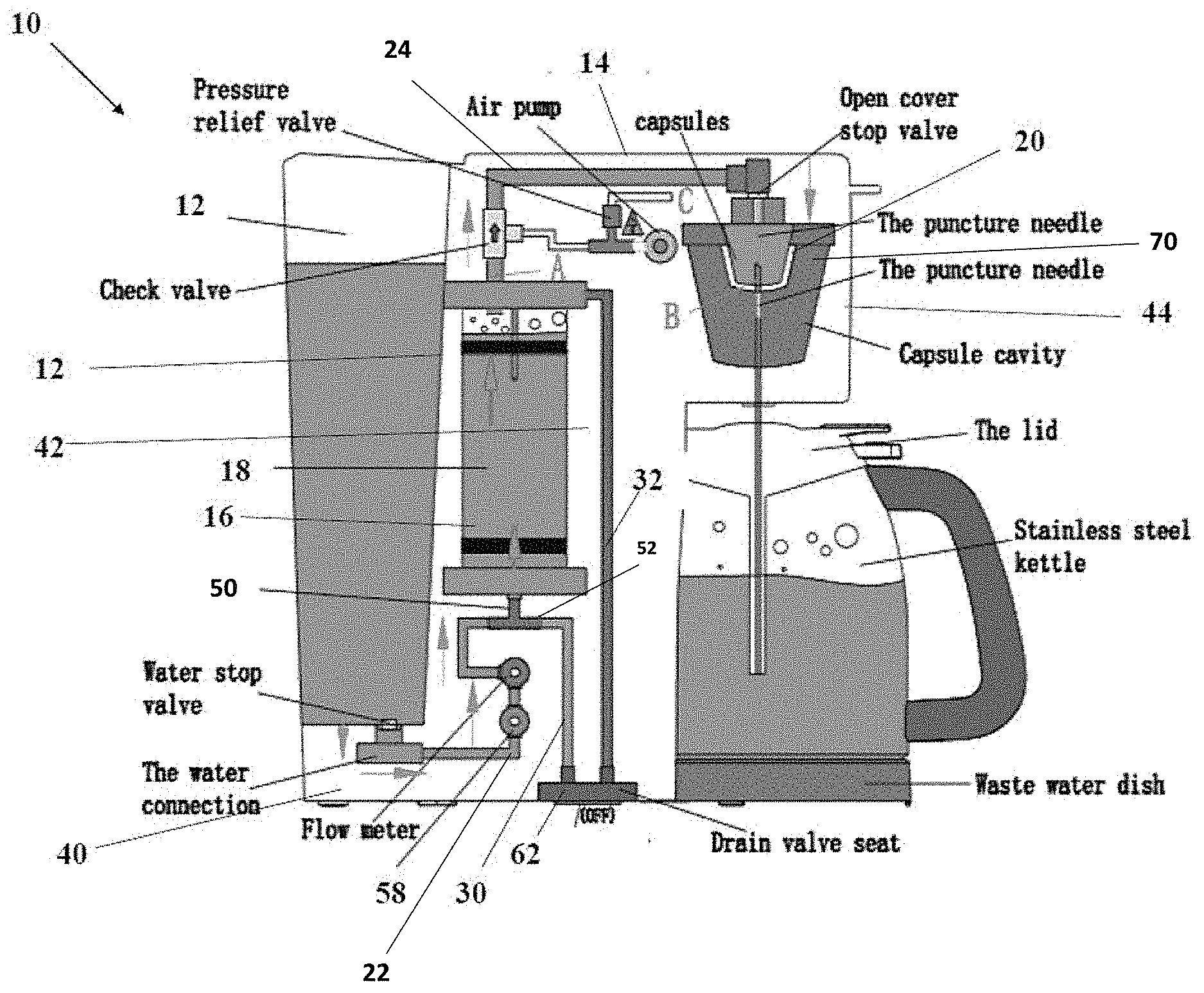
[0014] FIG. 1 is a schematic illustrating an embodiment of the disclosed automatic beverage maker;
[0015] FIG. 2 is another schematic of the embodiment of the disclosed automatic beverage maker shown in FIG. 1;
[0016] FIG. 3 is a schematic illustrating a temperature probe used for prior art brewing systems;
[0017] FIG. 4 is a schematic illustrating an embodiment of a temperature probe used for the disclosed beverage maker; and
[0018] FIG. 5 is an embodiment of a control panel template used for the disclosed beverage maker.
DETAILED DESCRIPTION OF THE INVENTION
[0019] While this invention is susceptible of embodiments in many different forms, there is shown in the drawings and will herein be described in detail at least one preferred embodiment of the invention with the understanding that the present disclosure is to be considered as an exemplification of the principles of the invention and is not intended to limit the broad aspect of the invention to any of the specific embodiments illustrated.
[0020] Referring to FIGS. 1-5, there is illustrated a beverage maker system, generally designated by the numeral 10. The particular illustrated beverage maker system 10 is for making hot beverages, such as tea and coffee. These systems are well-known in the art, utilizing sealed pods to produce single-servings of a hot beverage, such as coffee, tea or hot cocoa. The disclosed system 10 is comprised of a water reservoir 12 attached to a housing 14 having a pod-retention module 70. Positioned within the housing 14 is a sealed water tank 16 coupled to a heating system 74 to provide heated water to the pod-retention module 70. The heating system 74 is comprised of a heating element 18, a temperature probe 72, and a controller 76 electronically connected to the heating element 18 and probe 72. Water line 22 connects the reservoir 12 to the water tank 16, while water line 24 fluidly connects the water tank 16 to the pod-retention module 70.
[0021] In an alternate embodiment, the water reservoir 12, which typically requires manual refilling, may be provided by an on-demand water supply (not shown) using a dedicated water line connected to the system 10--i.e., directly to the sealed water tank 16. The dedicated water line as a water supply is preferred for high-use brewing systems.
[0022] The heating element 18 is preferably a surface heater, as shown in FIG. 4, which wraps about the water tank 16 to heat water within the tank 16. Other types of heating elements as known to those skilled in the art may be suitable.
[0023] The pod-retention module 70 comprises a pod cavity 20 into which a suitable beverage pod (not shown) can be positioned. The module 70 can be configured to accept beverage pods for single-servings or for larger, carafe-sized beverage production.
[0024] Additional components may include a drain line 30, an air-line 32, and dual water level sensors 78, all of which are connected to the sealed water tank 16. The drain and air lines, 30 and 32 respectively, facilitate draining of the tank 16. The water level sensors 78 determine when a sufficient quantity of water for brewing is in the sealed tank 16.
[0025] The housing 14 is preferably constructed of a typical plastic material and includes a base 40, a body (or mid-section) 42 and the pod-retention module 70. As illustrated in the FIGS., most of the components of the system 10 are positioned within and concealed by the body 42 of the housing 14. The reservoir 12 is typically detachable from an outer surface of the housing body 42, for cleaning purposes. The sealed tank 16 typically maintains a volume of water within and the heating element 18 keeps the volume of water warm while the system 10 is turned on. However, once the system 10 is turned off, the tank 16 may become a breeding ground for bacteria, molds, or the like. Accordingly, the ability to drain and properly flush the tank 16 on a regular basis helps maintain quality of the produced beverage.
[0026] The drain line 30 is preferably routed from a water inlet 50 for the water tank 16. A three-way valve 52 connected to the water inlet 50 is used to connect to both the first water line 22, which brings water to the tank 16 from the reservoir 12, and the tank drain line 30. While a separate water outlet may be created for the drain line 30, the use of the three-way valve 52 allows current beverage systems, which already have inlet lines, to be easily configured with a drain line without requiring modification to add a separate drain opening in the tank 16.
[0027] The air line 32 is preferably connected to the water tank 16 above the water line and allows air to flow into the tank 16 to replace water being drained from the tank. Both the air line 32 and the drain line 30 have ends 54 and 56 extending through the housing base 40 and opening at a bottom or side of the base 40. Preferably, a drain valve cover 62 attaches to both open ends, 54 and 56, to prevent drainage from tank 16. However, once the cover 62 is removed, water will drain from the tank 16 out the drain line 30 as air is pulled into the air line 32 until all water is removed from the tank 16. The drain valve cover 62 can then be replaced on the open ends 54 and 56.
[0028] Once all the water is removed, a cleaning cycle can be run to flush out the water tank 16. This can be accomplished by cycling through cleaning and rinsing steps, as needed. The cleaning step may require adding an appropriate cleaning solution to the reservoir 12, then turning the system 10 on to pump the solution into the water tank 16 via water pump 58. The draining procedure can then be used to remove the cleaning solution, as necessary. The rinsing step is similarly achieved using only water to flush through the water tank 16.
[0029] Referring to FIG. 4, an embodiment of the water tank heating system 74 is illustrated. As previously noted, the heating element 18 is preferably a surface heater which wraps around and contacts a substantial portion of the surface of the water tank 16. This helps provide a consistent heating of the water in the tank. Of course, as the warm water rises to the tank top 16T and the cooler water is injected from the tank bottom 16B, a temperature gradient is created in the tank 16.
[0030] For this reason, as set forth in the schematic of FIG. 3, the temperature probe 72 comprises two temperature sensors 82a,b. The first sensor 82a is preferably positioned in the tip of the probe 72, as shown, and is used to determine a temperature of incoming water to the sealed tank 16. The first sensor 82a is coupled to a controller 76 (FIG. 3). The second sensor 82b is preferably positioned in the probe 72 a distance of at least about 10 mm, and preferably at least about 15 mm from the first sensor 82a--i.e., higher in the sealed hot water tank 16--and is used to determine a temperature of the outgoing water. The second sensor 82b is also coupled to the controller 76 (FIG. 3). Preferably, both sensors 820 are negative temperature coefficient (NTC) thermistors.
[0031] In operation, returning to FIG. 4, the first sensor 82a is used to control the brewing temperature (T.sub.1) for the system 10, while the second sensor 82b is used to control the preheating temperature (T.sub.2) of the system 10. The brewing temperature (T.sub.1) is lower than the preheating temperature (T.sub.2). The unique two sensor configuration provides at least two benefits for the current brewing system 10. First, measuring brewing temperature at the lower point ensures that the water being delivered to the pod-retention module 70 for brewing is at no less than the desired temperature. Second, providing a preheating temperature allows the water in tank 16 to be maintained at a temperature which prevents overheating and dangerously increasing the pressure in the sealed tank 16.
[0032] With reference to FIG. 5, an embodiment of a template of the user interface 90 is shown. Along with the standard "on/off" button 92, the interface 90 provides a "strength" button 94 providing selection between three brew strengths and hot water, a "size" button 96 providing selection between several output sizes (e.g., 8 oz, 12 oz), a "temp" button 98 providing selection between water brew temperatures, and a "brew" button 100 for activating the brewing process. Lighted LEDs 102, including a "preheating" indicator 104, signal the current setting for each operation of the brew system 10.
[0033] The matter set forth in the foregoing description and accompanying drawings is offered by way of illustration only and not as a limitation. While particular embodiments have been shown and described, it will be apparent to those skilled in the art that changes and modifications may be made without departing from the broader aspects of applicants' contribution. The actual scope of the protection sought is intended to be defined in the following claims when viewed in their proper perspective based on the prior art.
* * * * *
D00000
D00001
D00002
D00003
D00004
D00005
XML
uspto.report is an independent third-party trademark research tool that is not affiliated, endorsed, or sponsored by the United States Patent and Trademark Office (USPTO) or any other governmental organization. The information provided by uspto.report is based on publicly available data at the time of writing and is intended for informational purposes only.
While we strive to provide accurate and up-to-date information, we do not guarantee the accuracy, completeness, reliability, or suitability of the information displayed on this site. The use of this site is at your own risk. Any reliance you place on such information is therefore strictly at your own risk.
All official trademark data, including owner information, should be verified by visiting the official USPTO website at www.uspto.gov. This site is not intended to replace professional legal advice and should not be used as a substitute for consulting with a legal professional who is knowledgeable about trademark law.