Electric Bed Package
SHIH; Chuan-Hang
U.S. patent application number 16/189132 was filed with the patent office on 2020-02-20 for electric bed package. The applicant listed for this patent is Chuan-Hang SHIH. Invention is credited to Chuan-Hang SHIH.
| Application Number | 20200054145 16/189132 |
| Document ID | / |
| Family ID | 64268588 |
| Filed Date | 2020-02-20 |


| United States Patent Application | 20200054145 |
| Kind Code | A1 |
| SHIH; Chuan-Hang | February 20, 2020 |
ELECTRIC BED PACKAGE
Abstract
An electric bed package includes a bedstead and a packing member. The bedstead includes an upper body supporting unit, a lower body supporting unit and a buttock supporting unit, which all have a flat shape. The upper and lower body supporting units are parallel stacked in a way that the buttock supporting unit is arranged by a lateral side of a stack of the upper and lower body supporting units and the buttock supporting unit is approximately perpendicular to the upper body supporting unit. The packing member packs and retains the bedstead therein. The electric bed package has a reduced volume, facilitating transportation thereof.
| Inventors: | SHIH; Chuan-Hang; (Lukang Township, TW) | ||||||||||
| Applicant: |
|
||||||||||
|---|---|---|---|---|---|---|---|---|---|---|---|
| Family ID: | 64268588 | ||||||||||
| Appl. No.: | 16/189132 | ||||||||||
| Filed: | November 13, 2018 |
| Current U.S. Class: | 1/1 |
| Current CPC Class: | A47C 20/10 20130101; F15B 15/1457 20130101; F15B 15/1414 20130101; A47C 20/08 20130101; A47C 1/024 20130101; A47C 19/04 20130101; A47C 20/041 20130101; A47C 19/005 20130101; A47C 23/005 20130101 |
| International Class: | A47C 19/00 20060101 A47C019/00; A47C 23/00 20060101 A47C023/00 |
Foreign Application Data
| Date | Code | Application Number |
|---|---|---|
| Aug 14, 2018 | TW | 107211106 |
Claims
1. An electric bed package, comprising: a bedstead including flat-shaped upper body, lower body and buttock supporting units, the upper body supporting unit and the lower body supporting unit being parallel stacked in a way that the buttock supporting unit is arranged by a lateral side of a stack of the upper and lower body supporting units and the buttock supporting unit is substantially perpendicular to the upper body supporting unit; and a packing member packing and retaining the bedstead therein.
2. The electric bed package as claimed in claim 1, wherein the buttock supporting unit has two lateral sides; the upper body supporting unit has a first outer surface and a first inner surface opposite to the first outer surface; the lower body supporting unit has a second outer surface and a second inner surface opposite to the second inner surface; the upper body supporting unit and the lower body supporting unit are stacked together in a way that the first inner surface of the upper body supporting unit faces the second inner surface of the lower body supporting unit and the first outer surface of the upper body supporting unit is opposite to the second outer surface of the lower body supporting unit.
3. The electric bed package as claimed in claim 2, wherein the two lateral sides of the buttock supporting unit are substantially flush with the first outer surface of the upper body supporting unit and the second outer surface of the lower body supporting unit, respectively.
4. The electric bed package as claimed in claim 2, further comprising a mattress attached to the bedstead; the packing member packs and retains the bedstead and the mattress therein.
5. The electric bed package as claimed in claim 4, wherein the mattress is abutted against the first outer surface or the second outer surface, or the mattress is abutted against the first inner surface and the second inner surface concurrently.
6. The electric bed package as claimed in claim 4, wherein the mattress is folded or comprises a plurality of cushion bodies.
7. The electric bed package as claimed in claim 4, further comprising a sealing beg, in which the mattress is received; an air pressure inside the sealing beg is less than 1 atm.
8. The electric bed package as claimed in claim 1, wherein the upper body supporting unit comprises a front base, a back supporting rack pivotally connected with the front base, and a front actuator having two ends; the two ends of the front actuator are pivotally connected with the front base and the back supporting rack, respectively.
9. The electric bed package as claimed in claim 1, wherein the lower body supporting unit comprises a rear base, a thigh supporting rack pivotally connected with the rear base, a lower leg supporting rack pivotally connected with the thigh supporting rack, and a rear actuator having two ends; the two ends of the rear actuator are pivotally connected with the rear base and the thigh supporting rack, respectively.
10. The electric bed package as claimed in claim 1, wherein the buttock supporting unit of the bedstead comprises a buttock supporting rack.
11. The electric bed as claimed in claim 1, wherein the packing member is selected from a group consisting of a rope, a belt, a box and a beg.
Description
BACKGROUND OF THE INVENTION
1. Field of the Invention
[0001] The present invention relates generally to an electric bed and more particularly, to an electric bed package.
2. Description of the Related Art
[0002] A conventional electric bed generally has considerable volume and weight as well as a relatively longer length. As a result, it is inconvenience and not cost-effective to transport the conventional electric bed, especially when the bed is shipped with a bouffant mattress having bulky volume. To solve the aforesaid problem, various foldable or dismantlable electric bedsteads, which have reduced volume to facilitate transportation, are developed and commercially available. However, no matter that the mattress and the bedstead are combinedly or individually packed, the package of current design still occupies a certain volume, resulting in that the usage efficiency of the space of the cargo container is not optimized. Therefore, a technical issue of reducing volume of the electric bed package so as to enhance the usage efficiency of the space of the cargo container and/or to increase convenience of transportation needs to be solved by manufacturers and practitioners in this industry field.
SUMMARY OF THE INVENTION
[0003] The present invention has been accomplished in view of the above-noted circumstances. It is an objective of the present invention to provide an electric bed package, which has a reduced volume so as to enhance the usage efficiency of the space of the cargo container for accommodating a plurality of the packages and/or to increase convenience of transportation thereof.
[0004] To attain the above objective, the present invention provides an electric bed package comprising a bedstead and a packing member. The bedstead includes an upper body supporting unit, a lower body supporting unit and a buttock supporting unit, which all have a flat shape. The upper and lower body supporting units are parallel stacked in a way that the buttock supporting unit is arranged by a lateral side of a stack of the upper and lower body supporting units and the buttock supporting unit is substantially perpendicular to the upper body supporting unit. The packing member packs and retains the bedstead therein. As such, the electric bed package has a reduced volume, thereby enhancing the usage efficiency of the space of the cargo container for accommodating a plurality of the packages, reducing the transporting cost, and increasing the convenience of transportation thereof.
BRIEF DESCRIPTION OF THE DRAWINGS
[0005] The present invention will become more fully understood from the detailed description given herein below and the accompanying drawings which are given by way of illustration only, and thus are not limitative of the present invention, and wherein:
[0006] FIG. 1 is an exploded view showing a mattress and a bedstead of a package according to a first embodiment of the present invention when they are not packed;
[0007] FIG. 2 is a perspective view of the bedstead of the package of the first embodiment of the present invention, showing a back supporting rack and a thigh supporting rack are in inclined positions;
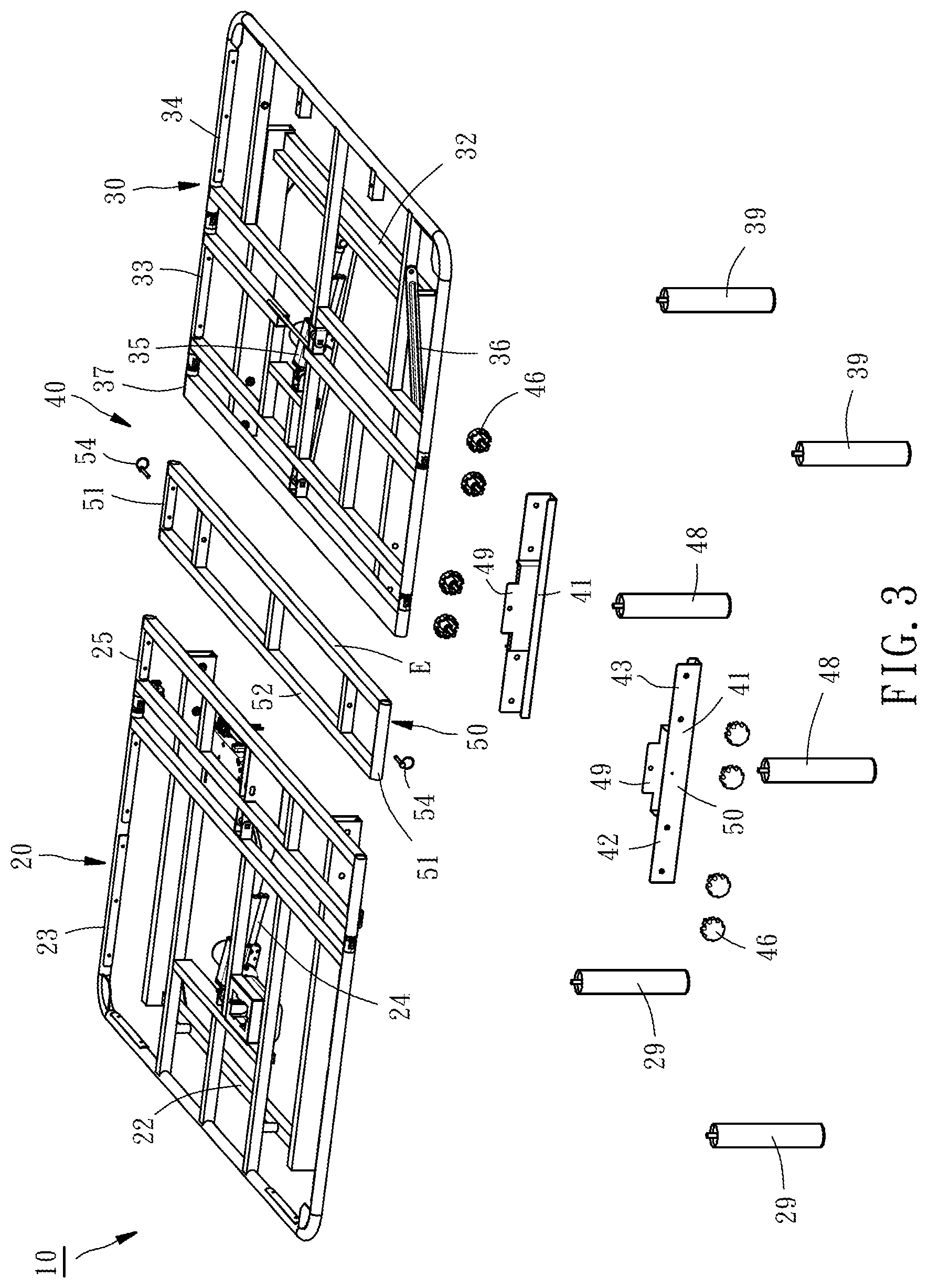
[0008] FIG. 3 is an exploded view of the bedstead of the package of the first embodiment of the present invention;
[0009] FIG. 4 is a schematic lateral side view of the package according to the first embodiment of the present invention;
[0010] FIG. 5 is a schematic lateral side view of a package according to a second embodiment of the present invention; and
[0011] FIG. 6 is a schematic lateral side view of a package according to a third embodiment of the present invention.
DETAILED DESCRIPTION OF THE INVENTION
[0012] The structure and technical features of the present invention will be detailedly described hereunder by three embodiments and accompany drawings. As shown in FIG. 4, an electric bed package 1 provided in accordance with a first embodiment of the present invention is composed of a bedstead 10, a mattress 60, and a packing member 70. The bedstead 10 is composed of an upper body supporting unit 20, a lower body supporting unit 30 and a buttock supporting unit 40.
[0013] In FIG. 4, the bedstead 10 of the package 1 is shown in a stacked manner. For better understanding the structure of the bedstead 10, FIGS. 1-3 show the detailed structure of the bedstead 10 of the first embodiment. As shown in FIG. 1, the mattress 60 is to be placed on the bedstead 10.
[0014] The upper body supporting unit 20 includes a front base 22, a back supporting rack 23 provided with a rear side pivotally connected with the front base 22, and a front actuator 24 having two ends pivotally connected with the front base 22 and the back supporting rack 23, respectively. The front base 22 has a rear section 25 pivotally connected with the back supporting rack 23. As such, the front actuator 24 can drive the back supporting rack 23 to swing between a horizontal position as shown in FIG. 1 and an inclined position as shown in FIG. 2. It is to be noted that the so-called front direction mentioned in the present invention is directed to the left direction of FIG. 1, and the so-called rear direction is directed to the right direction of FIG. 1. When the back supporting rack 23 stays at the horizontal position, the upper body supporting unit 20 is shaped like a flat member having a first outer surface S1 facing upward, and a first inner surface S2, which is opposite to the first outer surface S1 and faces downward. It is to be especially mentioned that the first outer surface S1 is mainly formed by the top surface of the back supporting rack 23 and the top surface of the rear section 25 of the front base 22 and the first outer surface S1 is approximately located on a same plane. The first inner surface S2 is mainly formed by the bottom surface of the front base 22 and the first inner surface S2 is approximately located on a same plane. Further, a front portion of the front base 22 is optionally equipped with two support legs 29 so as to raise the height of the bedstead 10.
[0015] The lower body supporting unit 30 includes a rear base 32, a thigh supporting rack 33 provided with a front side pivotally connected with the rear base 32, a lower leg supporting rack 34 having a front side pivotally connected with a rear side of the thigh supporting rack 33, a rear actuator 35 having two ends pivotally connected with the rear base 32 and the thigh supporting rack 33, respectively, and a link 36 having two ends pivotally connected with the rear base 32 and the lower leg supporting rack 34. The rear base 32 has a front section 37 pivotally connected with the thigh supporting rack 33. As such, the rear actuator 35 can drive the thigh supporting rack 33 to swing between a horizontal position as shown in FIG. 1 and an inclined position as shown in FIG. 2. During the process of swinging the thigh supporting rack 33 from the horizontal position to the inclined position, the lower leg supporting rack 34 will also swing from a horizontal position as shown in FIG. 1 to a lifted position as shown in FIG. 2. When the thigh supporting rack 33 and the lower leg supporting rack 34 both stay at the horizontal positions thereof, the lower body supporting unit 30 is shaped like a flat member having a second outer surface S3 facing upward, and a second inner surface S4, which is opposite to the second outer surface S3 and faces downward. The second out surface S3 is mainly formed by the opt surface of the front section 37 of the rear base 32, the top surface of the thigh supporting rack 33 and the top surface of the lower leg supporting rack 34, and the second outer surface S3 is approximately located on the same plane. The second inner surface S4 is mainly formed by the bottom surface of the rear base 32 and the second inner surface S4 is approximately located on a same plane. Further, a rear portion of the rear base 32 is optionally equipped with two support legs 39 so as to raise the height of the bedstead 10.
[0016] The buttock supporting unit 40 includes two middle bases 41, and a buttock supporting rack 50 detachably and transversely disposed on the two middle bases 41. Each middle base 41 has a front end 42 detachably connected with the front base 22, and a rear end 43 detachably connected with the rear base 32. The connecting ways among the middle bases 41, the front base 22 and the rear base 32 may vary and have many modifications. In this embodiment, four connecting members 46 are transversely inserted through one of the two middle bases 41 and threaded with the front base 22 and the rear base 32 respectively, such that the middle base 41, the front base 22 and the rear base 32 are connected together. In this embodiment, the connecting members 46 are realized as screws; however, in other embodiments, the connecting members 46 may be realized as pins or other members having connecting function. The amount of the connecting members 46 may vary, and the connecting members 46 may be horizontally arranged or vertically arranged. Further, each middle base 41 may be optionally equipped with a support leg 48 so as to raise the height of the bedstead 10.
[0017] The buttock supporting rack 50 has a flat shape with five longitudinal rods 51 extending in the front-and-rear direction and two transverse rods 52 extending in the left-and-right direction. Each transverse rod 52 has an outer lateral side E, and the two lateral sides E of the two transverse rods 52 are opposite to each other. Each middle base 41 includes a vertically extending limiting wall 49 located by one of the longitudinal rods 51. The buttock supporting rack 50 and the two middle bases 41 are connected by two pins 54 in a way that each pin 54 penetrates through the limiting wall 49 of one of the two middle bases 41 and associated longitudinal rod 51. By means of pulling off the two pins 54, the buttock supporting rack 50 can be separated from the two middle bases 41. The way of dismantling and assembling the buttock supporting rack 50 and the middle bases 41 can be conveniently operated thanks to the pins 54.
[0018] With the above-described structural design, the upper body supporting unit 20, the lower body supporting unit 30 and the buttock supporting unit 40 can be conveniently dismantled from each other by means of detaching the connecting members 46. Further, by means of detaching the pins 54, the buttock supporting rack 50 can be conveniently dismantled from the two middle bases 41. Furthermore, the support legs 29, 39 and 48 are respectively mounted to the front base 22, the rear base 32 and the middle bases 41 by screws, such that these support legs 29, 39 and 48 can be conveniently and respectively dismantled from the front base 22, the rear base 32 and the middle bases 41 by means of turning and loosening these support legs 29, 39 and 48.
[0019] The mattress 60 is integrally made by foam material, such as EVA sponge, in a foldable manner. In other embodiment, the mattress 60 includes a plurality of cushion bodies.
[0020] To pack the bedstead 10 and the mattress 60, the lower body supporting unit 30 is parallel stacked on above the upper body supporting unit 20 in a way that the first inner surface S2 of the upper body supporting unit 20 faces the second inner surface S4 of the lower body supporting unit, such that the first outer surface S1 is opposite to the second outer surface S3, as shown in FIG. 4. Thereafter, the buttock supporting rack 50 of the buttock supporting unit 40 is vertically arranged by a lateral side of the stack of the upper and lower body supporting units 20 and 30 in a way that the buttock supporting rack 50 is perpendicular or substantially perpendicular to the upper body supporting unit 20 or the lower body supporting unit 30, and the two lateral sides E are flush with the first outer surface S1 of the upper body supporting unit 20 and the second outer surface S3 of the lower body supporting unit 30 respectively, such that the upper body supporting unit 20, the lower body supporting unit 30 and the buttock supporting unit 40 approximately form a flat cube as a whole. And then, the other members of the buttock supporting unit 40, such as the two middle bases 41, the connecting members 46 and the pins 54, and the legs 29, 39 and 48 can be placed in between hollows of the upper body supporting unit 20 and the lower body supporting unit 30. In this way, the bedstead 10 can be flatly stacked with a relatively smaller volume. Especially, after the bedstead 10 is stacked, the longitudinal length of the bedstead 10, i.e. the length of the bedstead 10 in the front-and-rear direction, can be reduced to an extent that is less than a half of the original length (the longitudinal length of the bedstead 10 when the bedstead 10 extends). In this embodiment, the longitudinal length of the stacked bedstead 10 is reduced to about 45% of the original length of the extended bedstead 10. Thereafter, the mattress 60 is folded in half and placed on above the lower body supporting unit 30 in a way that the mattress 60 is attached on the second outer surface S3. Because the mattress 60 can be compressed by an external force to deform, the length of the folded and/or compressed mattress 60 is about equal to the length of the stack of the bedstead 10. As such, the folded and/or compressed mattress 60 and the stack of the bedstead 10 can be concurrently placed in a flat box, i.e. the packing member 70 in this embodiment. In other words, the packing member 70 packs and retains the bedstead 10 and the mattress 60 therein.
[0021] With the above-disclosed structural design, the electric bed package 1 may have a reduced volume, thereby enhancing the usage efficiency of the space of the cargo container for accommodating a plurality of the packages and reducing the transportation cost. In particular, the length of the package 1 of the present invention is reduced to less than a half of the original length of the extended bedstead 10, which breaks through the limitation that the length of the conventional package is about or more than a half of the original length of the extended bedstead, so that the volume of the package 1 is more in line with the requirement of mailing, air freight or ocean shipment, thereby reducing the transportation costs so as to achieve the objective of the present invention.
[0022] In other embodiments, the mattress 60 may be placed under the upper body supporting unit 20 and abutted against the first outer surface S1 of the upper body supporting unit 20. Further, a rope, belt, beg or other feasible member that can pack and retain the bedstead 10 and the mattress 60 may be used as the packing member 70 of the present invention in other embodiments.
[0023] It is to be noted that the electric bed package 1 of the present invention may comprise the bedstead 10 only in other embodiments. That is, the mattress 60 may be omitted in the electric bed package 1.
[0024] Based on the technical features of the present invention, various modifications to the structure of the electric bed package 1 of the present invention may be made. For example, the upper body supporting unit 20 and the lower body supporting units 30 may be respectively placed upside down and/or flipped left to right, or the upper body supporting unit 20 and the lower body supporting units 30 may exchange their positions, i.e. the upper body supporting unit 20 is stacked on above the lower body supporting unit 30. In any event, when the upper body supporting unit 20 and the lower body supporting unit 30 are overlappingly stacked together, the upper body supporting unit 20 and the lower body supporting unit 30 are arranged in a way that the first inner surface and the second inner surface are abutted with or face to each other and the first outer surface and the second surface are opposite to each other. For example, FIG. 5 shows an electric bed package 1a provided in accordance with a second embodiment of the present invention, which has a structure basically same as the structure of the electric bed package 1 of the first embodiment, except that the upper body supporting unit 20 is arranged upside down and stacked on above the lower body supporting unit 30. In this embodiment, the top surface of the upper body supporting unit 20 is regarded as the first outer surface S1' and the bottom surface is the first inner surface S2'. Similarly, the bottom surface of the lower body supporting unit 30 is regarded as the second outer surface S3' and the top surface of the lower body supporting unit 30 is the second inner surface S4'. The two lateral sides E of the buttock supporting rack 50 are flush with the first outer surface S1' and the second outer surface S3', respectively. No matter how the orientations and positions of the upper body supporting unit 20 and the lower body supporting unit 30 are changed, they should fall within the scope the claims of the present invention.
[0025] FIG. 6 shows an electric bed package 1b provided in accordance with a third embodiment of the present invention, which has a structure basically same as the structure of the electric bed package 1 of the first embodiment, except that the electric bed package 1b further comprises a sealing beg 80. After the mattress 60 is folded and received in the sealing beg 80, the air contained in the sealing beg 80 is expelled out by vacuum cleaner or other ways, such that the air pressure inside the sealing beg becomes less than one standard atmosphere (1 atm), thereby reducing the volume of the mattress 60. In particular, the longitudinal length of the mattress 60 is reduced to an extent that is about less than or equal to the longitudinal length of the upper body supporting unit 20 or the longitudinal length of the lower body supporting unit 30, such that the folded mattress 60 can be sandwiched between the upper and lower body supporting units 20 and 30. In this way, the mattress 60 is abutted against the first inner surface S2 of the upper body supporting unit 20 and the second inner surface S4 of the lower body supporting unit 30.
[0026] Another differentiated feature lies in that the longitudinal length of the buttock supporting rack 50 in this embodiment is greater than that of the first embodiment, and the longitudinal lengths of the upper and lower body supporting units 20 and 30 are less than those of the first embodiment. As such, the total length of the whole package can be reduced to less than 40% of the original length of the extended bedstead 10. Though the thickness of the package increases, the size of the package in this embodiment more fulfills with the transportation specification in other conditions.
[0027] It is to be further mentioned that the structures of the upper body supporting unit 20, the lower body supporting unit 30 and the buttock supporting unit 40 are not limited to the above-disclosed embodiments. Various modifications to the structures of the aforesaid units 20, 30 and 40 may be made. For example, the upper body supporting unit 20 may further comprise a head supporting rack pivotally connected with the back supporting rack 23 with an actuator for driving the head supporting rack to swing. That is, no matter how the structures of the upper body supporting unit 20, the lower body supporting unit 30 and the buttock supporting unit 40 are modified, they should fall within the scope of the claims of the present invention as long as the upper body supporting unit 20, the lower body supporting unit 30 and the buttock supporting unit 40 are arranged in a flat-shaped manner when they are packed. Further, in other embodiments, the buttock supporting rack 50 may be arranged in a way that the two lateral sides E of the buttock supporting unit 50 are not flush with the first outer surface S1 or S1' and the second outer surface S3 or S3', respectively.
[0028] The invention being thus described, it will be obvious that the same may be varied in many ways. Such variations are not to be regarded as a departure from the spirit and scope of the invention, and all such modifications as would be obvious to one skilled in the art are intended to be included within the scope of the following claims.
* * * * *
D00000
D00001
D00002
D00003
D00004
D00005
D00006
XML
uspto.report is an independent third-party trademark research tool that is not affiliated, endorsed, or sponsored by the United States Patent and Trademark Office (USPTO) or any other governmental organization. The information provided by uspto.report is based on publicly available data at the time of writing and is intended for informational purposes only.
While we strive to provide accurate and up-to-date information, we do not guarantee the accuracy, completeness, reliability, or suitability of the information displayed on this site. The use of this site is at your own risk. Any reliance you place on such information is therefore strictly at your own risk.
All official trademark data, including owner information, should be verified by visiting the official USPTO website at www.uspto.gov. This site is not intended to replace professional legal advice and should not be used as a substitute for consulting with a legal professional who is knowledgeable about trademark law.