Method Of Blasting
GOODRIDGE; Richard John ; et al.
U.S. patent application number 16/656239 was filed with the patent office on 2020-02-13 for method of blasting. This patent application is currently assigned to ORICA INTERNATIONAL PTE LTD.. The applicant listed for this patent is ORICA INTERNATIONAL PTE LTD.. Invention is credited to Rodney Wayne APPLEBY, Richard John GOODRIDGE, David Olaf JOHNSON, Thomas M MILLER.
| Application Number | 20200049476 16/656239 |
| Document ID | / |
| Family ID | 44904523 |
| Filed Date | 2020-02-13 |
| United States Patent Application | 20200049476 |
| Kind Code | A1 |
| GOODRIDGE; Richard John ; et al. | February 13, 2020 |
METHOD OF BLASTING
Abstract
An initiation device for initiation of an explosives charge, which comprises: a transceiver for receipt of wireless command signals; a control circuit for processing of wireless command signals received by the transceiver; and a light source that is suitable for initiation of the explosives charge and that is activated by the control circuit.
| Inventors: | GOODRIDGE; Richard John; (Redhead, AU) ; APPLEBY; Rodney Wayne; (Springfield Lakes, AU) ; JOHNSON; David Olaf; (Aurora, CO) ; MILLER; Thomas M; (Evergreen, CO) | ||||||||||
| Applicant: |
|
||||||||||
|---|---|---|---|---|---|---|---|---|---|---|---|
| Assignee: | ORICA INTERNATIONAL PTE
LTD. Singapore SG |
||||||||||
| Family ID: | 44904523 | ||||||||||
| Appl. No.: | 16/656239 | ||||||||||
| Filed: | October 17, 2019 |
Related U.S. Patent Documents
| Application Number | Filing Date | Patent Number | ||
|---|---|---|---|---|
| 13696519 | Jan 4, 2013 | |||
| PCT/US2011/035706 | May 9, 2011 | |||
| 16656239 | ||||
| Current U.S. Class: | 1/1 |
| Current CPC Class: | F42D 1/05 20130101; F42D 1/055 20130101; F42B 3/113 20130101 |
| International Class: | F42D 1/05 20060101 F42D001/05; F42D 1/055 20060101 F42D001/055; F42B 3/113 20060101 F42B003/113 |
Foreign Application Data
| Date | Code | Application Number |
|---|---|---|
| May 7, 2010 | AU | 2010901993 |
Claims
1. An explosive booster comprising: a working explosives charge that is a secondary explosive; a confined explosives charge disposed in an elongate tubular member that is embedded in and surrounded by the working explosives charge, wherein the confined explosives charge is a secondary explosive dosed with a heat transfer medium; a power supply; a laser diode coupled to the power supply and configured to emit light; a lens that focuses light emitted by the laser diode directly onto a portion of the confined explosive charge; a transceiver configured to receive wireless command signals sent from blast control equipment; a control circuit coupled to the power supply and in signal communication with the transceiver and the laser diode, wherein the control circuit is configured to process received wireless command signals and activate the laser diode in response to a specific wireless command signal; and a common housing in which each of the transceiver, the control circuit, and the laser diode reside.
Description
CROSS REFERENCE TO RELATED APPLICATIONS
[0001] This application is a Continuation of copending application Ser. No. 13/696,519, filed on Jan. 4, 2013, which is a national phase of PCT International Application No. PCT/US2011/035706 filed on May 9, 2011, which claims the benefit under 35 U.S.C. .sctn. 119(a) to Patent Application No. 2010901993, filed in Australia on May 7, 2010, all of which are hereby expressly incorporated by reference into the present application.
[0002] The present invention relates to a device for initiation of an explosives charge, to a blasting system including the device and to a method of blasting using the device. The invention is believed to have particular utility in commercial blasting operations, such as in mining and in oil and gas wells.
BACKGROUND TO INVENTION
[0003] In commercial blasting operations a bulk or packaged explosive is generally required to be initiated according to a predetermined blast design that specifies the time and sequence of initiation as between individual charges in a blast. In this context the bulk or packaged explosive is responsible for fracturing rock etc--it is the "working" or main explosives charge. This explosives charge is itself typically initiated by firing of a smaller explosives charge that is invariably provided under heavy confinement in the form of a cartridged detonator. The detonator is in signal communication with blast control equipment that is responsible for its firing. There is a continuing need to enhance the performance of commercial blasts by the development of blasting methodologies and componentry used. The present invention seeks to contribute in this regard.
SUMMARY OF THE INVENTION
[0004] Accordingly, in one embodiment the present invention provides an initiation device for initiation of an explosives charge, which comprises:
[0005] a transceiver for receipt of wireless command signals;
[0006] a control circuit for processing of wireless command signals received by the transceiver;
[0007] and
[0008] a light source that is suitable for initiation of the explosives charge and that is activated by the control circuit.
[0009] In use this initiation device will be operatively associated with an explosives charge that is capable of being initiated by the light source. Thus, in another embodiment there is provided an explosive device comprising an initiation device in accordance with the invention and an associated explosives charge, the explosives charge being provided and being adapted to be initiated by the light source.
[0010] The invention also provides a method of blasting using the initiation device of the invention, and a blasting system comprising the initiation device and associated blast control equipment.
[0011] As will be explained, the present invention combines wireless communication capability with light initiation of an explosives charge. This combination is believed to provide significant improvements over known blasting methodologies and componentry.
BRIEF DESCRIPTION OF THE DRAWINGS
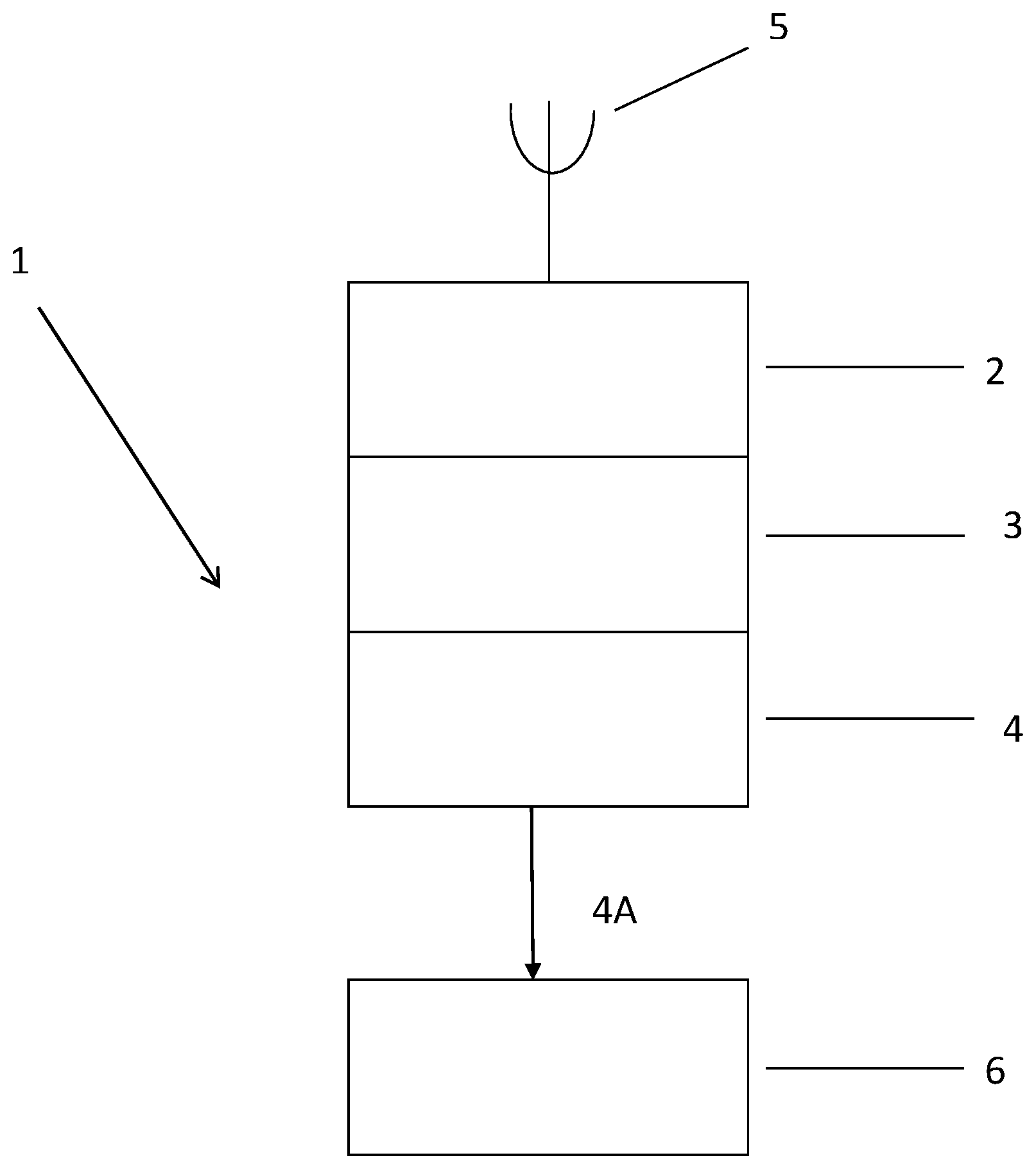
[0012] The FIGURE shows the device of the invention (1), having transceiver (2) for receiving wireless command signals (5), as well as a control circuit (3) for processing the wireless command signals (5) received by the transceiver (2), a light source (4), which is suitable for initiating explosive charge (6) by light (4A), discharged from the light source (4). The control circuit (3) comprises an integrated circuit (not shown) for preprogramming with a time delay to allow precise control of activation of the light source (4) when a wireless command FIRE signal is received by the transceiver (2).
DETAILED DISCUSSION OF THE INVENTION
[0013] The initiation device used in the present invention includes a transceiver and the function of this is to receive wireless communication signals sent from blast control equipment. The device can therefore be controlled remotely without the need for physical connections (e.g. wires) to convey command signals required in a blasting operation. Preferably, the transceiver has the capability for two-way communication so that such things as diagnostic and status checks can be conducted prior to a blast being initiated. The use of wireless communication in blasting operations is known in the art and transceivers useful in the present invention are known and available, or they may be made by the adaptation of known componentry.
[0014] The initiation device also includes a control circuit. The basic function of this is to process wireless command signals received by the transceiver and, subject to receipt of a suitable command signal, to activate the associated light source. In practice the control circuit is likely to have additional functional capability and will be responsive to a variety of wireless command signals received by the transceiver.
[0015] The control circuit will also typically include some form of timing mechanism to allow precise control of activation of the light source when a FIRE command is received by the transceiver. The control circuit will invariably be an integrated circuit. Such circuits are well known in the art. They are used for example in electronic detonators in order to control detonator functionality and timed initiation. One skilled in the art would therefore be familiar with the design of and componentry required in such circuits.
[0016] The initiation device also includes a light source and the function of this is to cause initiation of an explosives charge into or onto which light from the light source is discharged. The light source used in a particular device will be selected based on the type of explosives charge to be initiated--appropriate pairing of the light source and explosives charge is important to implementation of the present invention. Typically, the explosive charge will have been sensitised in some way to render it susceptible to initiation by a given light source. The light source may discharge directly into/onto the explosives charge or light from the source may be delivered to the explosives charge by a suitable wave guide, such as an optic fibre or by direct irradiation with or without a focussing lens.
[0017] An important characteristic of the present invention is that each initiation device has its own light source and in use this will typically be located in a borehole (or well hole or the like). The light source is controlled by the control circuit of the device. The device is under the (wireless) control of blast control equipment but otherwise the device is self-governing. This means for example that a single firing command can be sent to an array of initiation devices with the devices then being able to implement firing independently in accordance with the time delay programmed into the firing circuit. This allows increased control and reliability. This arrangement also allows a burning front to be achieved in a blast field in which a particular initiation device or devices has/have been (light) initiated whilst other initiation devices are in the process of timing down to (light) initiation.
[0018] This arrangement should be contrasted with a system in which a single (centralised) light source is used to deliver light through individual fibre optics to multiple points of intended initiation. This arrangement offers only crude control since a single light source is used to initiate multiple initiation events and this light source can only be either on or off. Optical switches would be required to control the transmission of light over individual fibre optics and this adds to operating complexity and cost. There may also be reliability issues with this type of system since there exists the possibility that a fibre optic may be damaged by detonation of charges in proximity before or during light transmission by the fibre optic. The approach used in the present invention does not suffer these drawbacks.
[0019] In an embodiment of the invention the initiation device includes a single transceiver and a plurality of associated control circuits and light sources. In this embodiment the transceiver has the capability of directing multiple independent control circuits and light sources associated with those control circuits. This allows a number of control units (and light sources) to be loaded in the same blasthole with all control circuits being in communication with a single transceiver. This enables each control circuit/light source to initiate an associated explosive charge at independent delay times whilst maintaining a burning front. In other words this embodiment allows multi-decking of a blasthole using the same transceiver, noting here that the down-hole componentry (control circuits and light sources) are independently powered. In this embodiment the transceiver may be provided at the surface at ground level although it is possible depending upon the nature of the wireless commands to the transceiver that it is positioned below ground in the blasthole.
[0020] In accordance with the invention wireless command signals are sent from blast control equipment to the transceiver of an initiation device. One or more mechanisms may be relied upon to ensure suitable transmission and receipt of the command signals.
[0021] In one embodiment the transceiver may need to be physically positioned so that wireless command signals can be received directly. For example, in this case, the transceiver may need to be provided at the top of a blasthole. In this case communication may take place using standard radio frequency transmission systems and protocols.
[0022] In another embodiment the transceiver may be positioned below ground level with wireless command signals being transmitted through the ground via low frequency signals. Low frequency communication is common through the mining industry and a number of systems to control blasting already exist.
[0023] A further possibility might involve the use of an aerial system extending from the transceiver to a point at which the wireless command signals can be received. For example, if the initiation device is positioned down a borehole, an aerial may extend from the transceiver along the length of the borehole to the surface.
[0024] In yet another embodiment of the present invention direct communication between blast control equipment and one or more initiation devices is not necessary for successful implementation. This embodiment involves indirect communication between these components by the formation of a low powered network in which one or more initiation devices act to relay a wireless command signal to a particular initiation device even if that device is out of range or otherwise unable to receive the wireless command signal directly. In this embodiment one or more initiation devices that is/are not intended to act on a wireless command signal relay the signal to one or more initiation devices that is/are intended to act on the command signal. It will be appreciated that in this embodiment the initiation devices will also have the ability to transmit wireless command signals. Formation of a cross-communicating network in this way can extend the range over which a wireless command signal may be effective. This approach is disclosed in International Patent Publication No. WO 2006/076777 entitled "Wireless detonator assemblies, and corresponding networks", the contents of which are incorporated by reference.
[0025] A clear advantage of using a network of initiation devices to ensure communication of command signals over a blast field is that if a communication "connection" to a particular device is lost, it may be possible to re-route the communication pathway around the lost connection thereby maintaining operability. The system may also be configured to diagnose communication problems thereby allowing corrective action to be taken. This should be contrasted with conventional direct communication systems where loss of a single communication pathway will usually bring down the whole system.
[0026] Another advantage of employing a low powered network to facilitate communication of wireless command signals is that the network has the potential to allow two-way communication. In this case a transceiver having two-way communication capability is used. This allows for example an initiation device to send information to blast control equipment on the current status of a network of the devices and for the blast control equipment to communicate to individual initiation devices timing protocols and firing commands. Thus, the control, timing and firing of a blast can be carried out using a remote (wireless) system with two-way communication allowing a blast operator to assess the status and performance of the blasting system before committing to a fire command. This adds an extra level of safety to a blasting operation. A further advantage is that the network is low powered and, as such, it should not interfere with other communications systems in operation at a blast site. Further, being a low powered network, no special operating license is likely to be required.
[0027] In the initiation device the transceiver is required to be in signal communication with the control circuit. The two components may be provided together, for example in a single housing, or they may be separate but suitably connected for signal communication for example, by wire, wireless or optical communication means. Likewise, the control circuit is required to be in signal communication with the light source in order to activate the light source as necessary. The control circuit and light source can be provided together, for example within the same housing, or they may be separate but suitably connected. The initiation device will also require a power supply to power the transceiver, control circuit and light source. The power supply may be physically associated with the device, or a component thereof, but this is not essential. In this regard safety requirements and regulations concerning the provision of a power supply on a downhole unit may need to be respected.
[0028] The power supply may be conventional in design, such as a low voltage battery (possibly located with the light source component) or a supercapacitor charged from a battery. In the latter case the supercapacitor may be charged using a battery provided at the surface with the supercapacitor provided as part of the downhole componentry.
[0029] In another embodiment, one or more components of the device may be powered by less conventional means. For example, it may be possible to use environmental means, such as solar power. Other possibilities may exist depending upon how the present invention is implemented in practice. It may be desirable however for the device of the invention to function without the need to use a conventional power source such as a battery.
[0030] It will be appreciated from the preceding paragraphs that the transceiver functionality and the light source may be physically separated from each other (the control circuit can be associated with either). Thus, the transceiver could be located at or above ground level and the light source (the firing functionality of the device) provided adjacent or on top of an explosives train (of working explosives) in a borehole. This offers a number of advantages as follows: [0031] Simplified design for receipt of wireless command signals. [0032] The transceiver can be used to transmit blast performance data during and possibly after a blast. For example, if the transmitter and control unit are connected via wires, the wire could be used to measure VOD in the hole via a change in resistance and this information transmitted back to the control centre. [0033] The size of the down-hole componentry may be reduced and this will be beneficial for small bore applications. In this regard current solid state lasers may be of very compact design. [0034] As noted, it may be possible for a single transceiver, for example located at the surface, to control the activation of a number of down-hole firing units by having multiple output points which allow connection of a number of units. This would be beneficial for holes in which there are multiple detonators, for example, multi decked holes.
[0035] The explosives charge that is light initiated in accordance with the present invention may be used to initiate an associated "working" or main explosives charge. In this case the light initiated explosives charge is relatively small but selected to nevertheless be effective in detonating the main explosives charge. In this case the light initiated explosive charge may be provided under heavy confinement as per a conventional cartridge detonator. Light can be delivered into the cartridge direct or via a fibre optic.
[0036] In another embodiment the light initiated explosives charge is used to detonate an associated main explosives charge but the arrangement is detonator free. In this case the light explosive charge is provided in direct contact with at least part of the main charge or the two may be separated by a membrane that does not influence detonation of the main explosives charge. This approach is described in International Patent Publication No. WO 2008/113108 entitled "Initiation of explosives materials", the contents of which are incorporated herein by reference. The latter stipulates use of an optic fibre to convey light but this is not essential in accordance with the present invention.
[0037] Accordingly, in this embodiment the invention provides a detonator free blasting system which comprises:
[0038] a working explosive charge;
[0039] a confined explosives charge; and
[0040] an initiation device in accordance with the present invention, wherein the initiation device is provided to deliver light to the confined explosives charge and the confined explosives charge is adapted to be initiated by that light and wherein initiation of the confined explosives charge causes initiation of the working explosive.
[0041] In accordance with this embodiment the working explosives charge is initiated by detonation of the confined explosives charge. In turn initiation of the confined charge is caused by irradiation of the confined explosive by a suitable light source. Thus, the working explosive is initiated without using a conventional detonator device.
[0042] In accordance with this embodiment initiation is achieved by irradiating the confined charge until ignition of it occurs. The confined charge is confined such that this initial ignition propagates to full detonation. The confined charge and working charge are provided relative to one another such that detonation of the confined charge causes initiation of the working charge. In an embodiment of the invention a portion of the confined charge and a portion of the working charge may be in direct contact. However, in other embodiments this may not be essential provided that the intended operative relationship between the charges is retained. For example, in certain embodiments, the charges may be separated by a membrane, or the like. In this case the membrane, or the like, may be included for ease of manufacture; the membrane (or like) does not influence detonation of the working charge.
[0043] The working explosives charge that is used is generally a secondary explosive too. The blasting system of the invention may therefore be free of primary explosives. The working explosives charge may be the same as or different from the light initiated explosives charge. When the charges are of the same explosives material the invention may be implemented by suitable confinement of a portion of the bulk explosive.
[0044] An important aspect of this embodiment is the way in which the confined explosives charge is confined since it has been found that the geometry of the confinement is critical to the successful detonation of the working explosive. Thus, the confined explosive charge should be confined in such a manner to contain initial ignition of the confined charge and to allow subsequent propagation to full detonation. A variety of confinement means (geometry and material) may be employed in implementation of the embodiment of the present invention.
[0045] In one embodiment the confined explosive charge may be confined in an elongate tubular member. Usually, this will be of circular cross-section, although this is not mandatory. When an elongate tubular member is used, the internal diameter of the tubular member should be greater than the critical diameter for the explosive being confined. When the confined explosive charge is strongly confined, for example, when the confinement means is made of a metal, the internal diameter of the tubular member may be up to 3 times larger than the critical diameter for the explosive being confined.
[0046] A typical tubular member of circular cross-section useful in the present invention generally has an internal diameter of about 2 to about 5 mm, for example about 3 mm, and a length of up to about 110 mm, for example from 20 to 110 mm. The length of the tubular member required for transition of the confined explosives charge will vary as between different types of explosive. For example, for PETN the minimum length of the tubular member will be about 30 mm, whereas for pentolite the minimum length will be about 90 mm (for an internal diameter of about 3 mm).
[0047] The confinement means may take on other geometries. Thus, spherical or conical confinement means may be used. Examples of suitable materials for the confinement means include metals and metal alloys, for example aluminium and steel, and high strength polymeric materials.
[0048] For the purposes of illustration, in the following, the invention will be described in connection with a tubular elongate member of circular cross-section as confinement means.
[0049] Typically, the working explosives charge is provided in (direct) contact with a portion of the confined explosives charge. When the confined explosives charge is confined in an elongate tubular member the requisite contact may be achieved via an end of the tubular member in which the confined portion is confined (that end being remote from the end of the tubular member to which laser light is delivered through the fibre optic). When other geometries of confinement means are employed it is important that at least a portion of the confined explosive charge is in contact with the working explosive.
[0050] In an embodiment a fiber optic may be used to communicate light from the light source to the confined explosives charge. This can be done by providing one end of the (exposed) fibre optic in contact with, or embedded in, the confined explosive charge. Thus, one end of the fibre optic may be inserted into an end of the tubular member in which the explosive charge is confined. The fibre optic will usually have a diameter of from 50 to 400 .mu.m.
[0051] In a related embodiment of the present invention the exposed end of the fibre optic may be provided adjacent to but not in contact with the (external surface of the) confined explosive charge. It has been found that providing a gap (of air) between the end of the (exposed) fibre optic and the confined explosive charge has an effect on heat transfer to the confined explosive and thus on the delay time between when laser light is discharged through the fibre optic and when the confined explosive is initiated. More specifically, it is believed that the gap acts as an insulator that facilitates efficient heat transfer to the confined explosive by minimizing/avoiding reverse conduction effects. Preferably, the exposed end of the fibre optic is provided at a short distance away from the surface of the confined explosive in the tubular member. Typically, this short distance is from 5 .mu.m to 5.0 mm
[0052] The fibre optic is of conventional design and is provided with a layer of cladding. This may be removed at one end of the fibre optic when the fibre optic is being positioned relative to the confined explosive provided in the tubular member. The characteristics of the fibre optic will be selected based on amongst other things the wavelength of laser light to be communicated to the confined explosive. By way of example the wavelength is typically from 780 to 1450 nm.
[0053] The exposed end of the fibre optic is usually held in an appropriate position relative to the confined explosive by means of a suitable connector. An O-ring may be used to grip the exposed end of the fibre optic and to prevent leakage of gas.
[0054] In other embodiments it is not necessary to use a fibre optic to communicate light from the light source to the confined explosives charge. This may simplify design and manufacture, and be more economical. In one such embodiment it may be possible to communicate light directly from the light source to the confined explosives charge. Here the outlet of the light source would be provided in very close proximity or even touching the confined explosive charge. For example, the "window" of a laser diode may be provided adjacent to or in contact with the explosive charge. In another embodiment a lens may be used to focus light from the light source onto the explosive charge. For example, it may be possible to replace the "window" portion of a laser diode with a (sapphire) lens that focuses light emitted from the diode onto the explosive. This approach may enhance efficiency.
[0055] The working explosives charge that it is desired to detonate is generally provided in (direct) contact with at least a portion of the confined explosives charge. Typically, this contact will occur at the end of the tubular member in which the confined explosive is confined remote from the end of the tubular member associated with the fibre optic. Depending upon the form in which the explosive charge is provided, the explosives charge may also surround the tubular member in which the confined explosive is confined. In other words the tubular member may be embedded in the explosives charge.
[0056] In a related embodiment the explosives charge that is to be light initiated takes the form of a booster, for example a pentolite booster. In this case the confined explosives charge, preferably PETN or pentolite, is provided in an elongate tubular member that is embedded in the booster. The booster may be designed accordingly to accommodate the tubular member. Thus, the tubular member may be provided and secured in the booster in a suitable well, as is the case for detonator initiated boosters. Otherwise, conventional boosters may be used to implement this embodiment.
[0057] Alternatively, in another related embodiment of the invention, the pentolite booster may be cast around and with a suitable tubular member. In this case it may be possible to implement the invention using a one-piece booster comprising a shell/casing and an integrally formed tubular member extending into a cavity defined by the shell/casing. Suitable explosives material(s) may then be cast into the shell/casing and tubular member.
[0058] These embodiments of the present invention relating to the booster may have practical application in seismic exploration where (pentolite) boosters are used to generate signals (shock waves) for analysis to determine geological characteristics in the search for oil and gas deposits. The present invention thus extends to use of this embodiment of the invention in seismic exploration.
[0059] It is also possible for the working explosives charge to take the form of a length of detonating cord. In this case the end of the detonating cord is typically provided in direct contact with at least a portion of the confined explosives charge. Any suitable retainer or connector may be used to ensure that this direct contact is maintained prior to use. Initiation of the detonating cord aside, the detonating cord may be used in conventional manner. Instantaneous detonation of detonating cord across multiple blastholes could prove advantageous in pre-split and tunnel perimeter blasting operations. In another embodiment the detonating cord may itself be used to initiate a booster, for example a booster comprising an emulsion explosive. In this case one end of the detonating cord will be embedded in the booster explosive with the other end of the cord being available for light initiation in accordance with the present invention.
[0060] In another embodiment the confined and working explosives charges may be an emulsion explosive material. Conventional emulsion explosive material may be used in this regard. In this embodiment a portion of the emulsion explosives material may be confined in a suitable elongate tubular member and immersed/embedded in the working charge emulsion. In this embodiment (and for all others) the nature and dimensions of the means used for confinement may be manipulated in order to optimise implementation of the invention.
[0061] In another embodiment the light initiated explosives charge may itself be adequate to achieve the desired blast outcome. For example, the explosives charge deployed in a suitable device configuration may be adequate to perforate a well casing in oil or gas exploration.
[0062] The explosives charge to be initiated by light and the light source are selected based on the required outcome and the two must be paired accordingly. Examples of light sources that may be used include solid state lasers, laser diodes, LEDs and other electronic light sources. Compact design and low power consumption are desirable characteristics for the light source. By way of example a 1-10 W power laser may be suitable for use in the invention. The laser wavelength may be within the near infra-red region and indeed this is preferred, although other wavelengths may be used. A fibre optic and/or lens may be required to channel and focus the laser output, although direct irradiation of the explosives charge would be preferred as this would simplify overall design.
[0063] Usually, the light initiated explosive is a secondary explosive material, such as PETN, tetryl, RDX, HMX, pentolite, and the like. The use of PETN or pentolite tends to be preferred. It is possible however that the explosives charge is a conventional emulsion explosive, such as a water-in-oil emulsion explosive, or a water-gel explosives material.
[0064] Depending upon the characteristics of the light source and explosives charge, it may be necessary to dose the explosives charge with a heat transfer medium to enhance coupling of the light energy irradiated from the light source and the explosive charge. Typically, the heat transfer medium is a light absorbing material that has an absorption band in the wavelength of the light being used. Examples of heat transfer media include carbon black, carbon nanotubes, nanodiamonds and laser dyes. Such materials are known in the art and are commercially available.
[0065] In an embodiment of the invention it may be possible to use a conventional camera flash to initiate an explosives charge. It is known for example that unpurified single wall carbon nanotubes (SWCNT) can be caused to ignite when light is applied to them from a standard camera flash. This is believed to be due to oxidation of iron nanoparticle catalysts that are present at the ends or on the surface of the nanotubes.
[0066] The flash initiation reaction is not particularly violent since only small regions of the nanotubes seem to show reaction. However, if nano-magnesium and/or nano-iron is mixed with nano-iron particles a more intense and violent reaction can result with significant amounts of heat being given off. Typically, the particle size for the iron and magnesium particles will be 2 to 4000 .mu.m but preferably in the order of 6 to 100 .mu.m. The reaction may be a thermite reaction with the formed oxide. The additional heat associated with that reaction may enable initiation of an explosives charge dosed with the nanotubes, or a blend of nano-iron and nano-magnesium particles. It is possible that the same effect may be achieved using a high intensity LED or laser rather than a camera flash.
[0067] In the same way, other additives that serve as a thermal source and that actively take part in detonation reactions may be included in the confined explosive. Such materials include nitrated nanomaterials, silicon nanowires and other optically sensitive fuels. The amount of such materials may be up to 10% by weight of the confined explosives charge. Such materials may be used together with a heat transfer medium, or alone. The use of one or more heat transfer media and/or optically sensitive materials may allow detonation to be achieved with irradiation energies orders of magnitude lower than when such media and/or materials are not used.
[0068] The invention also relates to a method of blasting using an initiation device in accordance with the invention. In this case the light source of the device is provided in operative association with an explosive charge that is adapted to be light initiated by the light source used in the device. The method comprises the transmission of a suitable wireless command signal to the device, the command signal being received by the transceiver and processed by the control circuit. The control circuit activates the light source and this causes the explosives charge to be initiated. The explosives charge is typically associated with and causes initiation of an associated working explosives charge.
[0069] The invention further provides a blasting system comprising an initiation device in accordance with the invention and blast control equipment that is adapted to transmit wireless command signals to the device.
[0070] The present invention may have particular use in the Oil & Gas (O&G) industry. Possible applications within this industry include use in the completion of O&G wells, specifically the initiation of explosives within perforation guns. Perforation guns are used in the final stage (completion) of an O&G well to break through the concrete (and/or other materials) casing laid down during the well making process. A further purpose of the perforation gun is to fracture the formation holding the oil in order to stimulate oil and/or gas flow. This may happen whether the well casing is intact or not. Perforation of O&G wells is generally carried out by specialized personnel through dedicated service companies, although other arrangements are possible.
[0071] The presence of primary explosives (amongst other things) in the perforation gun firing train means that once the explosive train is established on (or near) an O&G well working platform a range of activities must cease, resulting in a significant loss of productivity from the well. Removing primary explosives from this environment thus provides a tangible economic benefit in addition to the substantial safety advantage inherent in secondary (vs. primary) explosives. The present invention enables direct photo-initiation of secondary explosives and this will remove this hazard and allow a significantly wider range of activities to continue.
[0072] A further application in the O&G industry is the use in exploration for O&G through seismic surveys. Explosives are important sources of seismic energy used to uncover underground geologic features able to retain O&G. Seismic surveys entail burying of one or more explosives charges to pre-determined depths (e.g. shot-holes) in arrays of particular design. Geophone (or other measuring devices) arrays of are also established to detect reflected (as well in some cases direct) seismic energy. The explosives are then initiated, measurements of resultant (including background) seismic energy are recorded and analysis is performed to visualize relevant geologic features.
[0073] Explosive arrays are generally relatively large, consisting of 10's, 100's or even 1000's of individual charges. These charges are generally deployed by relatively small teams of people and a significant time can elapse between loading the first and last charges giving rise to long periods where live explosives are left in shot-holes. Further delays can arise due to technical activities surrounding a survey including, but not limited to, establishing the firing train, measurement array or other related activities. Even further delays may be caused by non-specific issues including scheduling of staff/equipment, weather or other seasonal issues. Taken together, these delays (and others not specified) result in potentially long explosive sleep-times, i.e. explosives deployed before initiation. Seismic survey applications can result in longer sleep times than most other explosive applications making the removal of primary explosives particularly preferable in that context.
[0074] As noted the present invention allows the use of primary explosives materials to be avoided. One of the safety benefits of this in seismic exploration is that the overall sensitivity to detonation by non-specific means is significantly reduced. This is advantageous during the survey as it reduces the possibility of an unintended detonation. It is also important following completion of the survey as it is accepted that a certain proportion of charges deployed will fail to detonate. This proportion can be up to 10% depending on local conditions but is generally considerably lower. Due to the hazards involved in recovering misfired charges, many are left in place and are abandoned. The presence of highly sensitive primary explosives in these deployed charges means that shock, or another event, can lead to unintended detonation by non-specific stimulus. The chances of this are significantly reduced if the present invention is employed in order to avoid the use of primary explosives.
[0075] Notwithstanding the reduced sensitivity of secondary explosives to a wide range of stimuli, the photo-initiation system will fire only in response to a specific stimulus. Proven, secure systems to generate this stimulus exist and include, but are not limited to electronic systems, able to generate a fire, no fire or disarm signals. It is highly unlikely that the fire signal will be generated in the environment of an abandoned charge by chance.
[0076] A further advantage of removal of primary explosives is environmental, in that many widely used primary explosives include highly toxic and environmentally stable compounds. One example of this is the wide use of lead azide in detonators--the azide component is a highly toxic poison and lead is a recognized environmental pollutant that cannot be broken down by any natural process. Whilst many secondary explosives are classed as recalcitrant pollutants, natural mechanisms do exist in nature for their efficient degradation with biodegradation reported for all secondary explosives in wide use.
[0077] Many modifications will be apparent to those skilled in the art without departing from the scope of the present invention
[0078] Throughout this specification and the claims which follow, unless the context requires otherwise, the word "comprise", and variations such as "comprises" and "comprising", will be understood to imply the inclusion of a stated integer or step or group of integers or steps but not the exclusion of any other integer or step or group of integers or steps.
[0079] The reference in this specification to any prior publication (or information derived from it), or to any matter which is known, is not, and should not be taken as an acknowledgment or admission or any form of suggestion that that prior publication (or information derived from it) or known matter forms part of the common general knowledge in the field of endeavour to which this specification relates.
* * * * *
D00001
XML
uspto.report is an independent third-party trademark research tool that is not affiliated, endorsed, or sponsored by the United States Patent and Trademark Office (USPTO) or any other governmental organization. The information provided by uspto.report is based on publicly available data at the time of writing and is intended for informational purposes only.
While we strive to provide accurate and up-to-date information, we do not guarantee the accuracy, completeness, reliability, or suitability of the information displayed on this site. The use of this site is at your own risk. Any reliance you place on such information is therefore strictly at your own risk.
All official trademark data, including owner information, should be verified by visiting the official USPTO website at www.uspto.gov. This site is not intended to replace professional legal advice and should not be used as a substitute for consulting with a legal professional who is knowledgeable about trademark law.