Frac Plug with Sealing Element Compression Mechanism
Coon; Robert Joe ; et al.
U.S. patent application number 16/056679 was filed with the patent office on 2020-02-13 for frac plug with sealing element compression mechanism. The applicant listed for this patent is PetroQuip Energy Services, LLP. Invention is credited to Robert Joe Coon, Antonio B. Flores, Roddie R. Smith.
| Application Number | 20200048981 16/056679 |
| Document ID | / |
| Family ID | 69405663 |
| Filed Date | 2020-02-13 |

| United States Patent Application | 20200048981 |
| Kind Code | A1 |
| Coon; Robert Joe ; et al. | February 13, 2020 |
Frac Plug with Sealing Element Compression Mechanism
Abstract
A frac plug is provided. The frac plug may include a plug body, a slip, a sealing element, and a compression ring. The plug body may have a first end portion and a second end portion. The slip may be circumferentially disposed about the plug body and configured to expand and couple the frac plug to a tubular section. The sealing element may be circumferentially disposed about the plug body and configured to create a seal between the plug body and an inner surface of the tubular section. The compression ring may be circumferentially disposed about the plug body proximate to the first end portion and abut the sealing element. The compression ring may be configured to expand when shifted along the plug body to compress the sealing element and retain the sealing element in a compressed position.
| Inventors: | Coon; Robert Joe; (Missouri City, TX) ; Smith; Roddie R.; (Katy, TX) ; Flores; Antonio B.; (Cypress, TX) | ||||||||||
| Applicant: |
|
||||||||||
|---|---|---|---|---|---|---|---|---|---|---|---|
| Family ID: | 69405663 | ||||||||||
| Appl. No.: | 16/056679 | ||||||||||
| Filed: | August 7, 2018 |
| Current U.S. Class: | 1/1 |
| Current CPC Class: | E21B 33/128 20130101; E21B 33/1216 20130101; E21B 33/129 20130101; E21B 33/1293 20130101 |
| International Class: | E21B 33/128 20060101 E21B033/128; E21B 33/129 20060101 E21B033/129 |
Claims
1. A frac plug, comprising: a plug body having a first end portion and a second end portion; a slip circumferentially disposed about the plug body, the slip configured to expand and couple the frac plug to a tubular section; a sealing element circumferentially disposed about the plug body and configured to create a seal between the plug body and an inner surface of the tubular section; and a compression ring circumferentially disposed about the plug body proximate to the first end portion and abutting the sealing element, the compression ring configured to expand when shifted along the plug body to compress the sealing element and retain the sealing element in a compressed position.
2. The frac plug of claim 1, wherein the compression ring comprises a composite material.
3. The frac plug of claim 1, wherein the compression ring comprises a ductile metal.
4. The frac plug of claim 1, wherein the plug body comprises: a first sub; and a second sub threadably engaged with the first sub.
5. The frac plug of claim 1, wherein the slip comprises: a taper on an inner surface of the slip that extends along an axial length of the slip between a first end portion and a second end portion; and a left-hand thread pattern defined by an outer surface of the slip and extending from the first end portion of the slip along a portion of the axial length.
6. The frac plug of claim 5, wherein the slip further comprises at least one thread defined by the outer surface of the slip and adjacent the second axial end portion of the slip, the at least one thread having a crest that is angled away from the left-hand thread pattern.
7. The frac plug of claim 1, wherein the compression ring comprises: an annular body having an inner surface; and a plurality of beads embedded in the inner surface of the annular body and configured to increase friction between the compression ring and the plug body.
8. The frac plug of claim 7, wherein the inner surface of the annular body defines a thread pattern and the plurality of beads are embedded between threads of the thread pattern.
9. The frac plug of claim 1, wherein an inner surface of the compression ring is tapered.
10. The frac plug of claim 1, wherein the compression ring is configured to shift along a tapered portion of an outer surface of the plug body.
11. A frac plug comprising: a plug body, comprising: a first sub having a taper extending along a portion of an outer surface, and a second sub threadably engaged with the first sub; a slip circumferentially disposed about the plug body between the first sub and the second sub, the slip configured to expand and couple the frac plug to a tubular section; a sealing element circumferentially disposed about the first sub, the sealing element configured to create a seal between the plug body and an inner surface of the tubular section; and a compression ring having a tapered inner surface, the compression ring circumferentially disposed about the first sub and abutting the sealing element, and configured to expand when shifted along the taper of the first sub to compress the sealing element and retain the sealing element in a compressed position.
12. The frac plug of claim 11, wherein the compression ring comprises a composite material.
13. The frac plug of claim 11, wherein the compression ring comprises: an annular body having an inner surface; and a plurality of beads embedded in the inner surface of the annular body and configured to increase friction between the compression ring and the first sub.
14. The frac plug of claim 13, wherein the inner surface of the annular body defines a thread pattern and the plurality of beads are embedded between threads of the thread pattern.
15. The frac plug of claim 11, wherein the second sub is threadably engaged with the first sub via a lock ring.
16. The frac plug of claim 11, wherein the slip comprises: a taper on an inner surface of the slip that extends along an axial length of the slip between a first end portion and a second end portion; and a left-hand thread pattern defined in an outer surface of the slip and extending from the first end portion of the slip along a portion of the axial length.
17. The frac plug of claim 16, wherein the slip further comprises at least one thread defined in the outer surface of the slip and adjacent the second axial end portion of the slip, the at least one thread having a crest that is angled away from the left-hand thread pattern.
18. A method for setting a frac plug within a tubular section disposed in a wellbore, the method comprising: disposing the frac plug on a running tool; positioning the frac plug within the tubular section using the running tool; compressing the frac plug with the running tool; shifting a compression ring of the frac plug along an outer surface of the frac plug to expand the compression ring and compress a sealing element of the frac plug to create a seal between the frac plug and an inner surface of the tubular section, wherein friction between the compression ring and a plug body of the frac plug prevents movement of the compression ring away from the sealing element; and engaging a left-hand thread pattern defined in an outer surface of a slip of the frac plug with the inner surface of the tubular section to retain the frac plug within the tubular section.
19. The method of claim 18, wherein the frac plug further comprises a first sub and a second sub, and the method further comprises ratcheting the second sub along a threadable engagement with the first sub to hold the frac plug in a compressed position.
20. The method of claim 19, wherein the frac plug further comprises a back-up ring, and the method further comprises expanding the back-up ring along a taper of the first sub such that the back-up ring contacts the tubular section and prevent extrusion of the sealing element.
Description
CROSS-REFERENCE TO RELATED APPLICATIONS
[0001] This application claims the benefit of U.S. Provisional Patent Application having Ser. No. 62/544,032, which was filed Aug. 11, 2017. The aforementioned patent application is hereby incorporated by reference in its entirety into the present application to the extent consistent with the present application.
BACKGROUND
[0002] In oil and gas production, it is sometimes beneficial to stimulate a reservoir by pumping in high pressure fluids and particulates, such as sand. In order to do this, one or more tubular sections of a tubular installed in the well may need to be isolated for a period of time and re-opened so the well can be produced.
[0003] One means of isolation is a frac plug. A frac plug is a hollow, cylindrical plug which can be installed in the tubular to isolate one or more sections. Current designs generally utilize a sealing ball that is pumped into place against the plug. Seating the sealing ball stops fluid flow through the bore of the frac plug. In addition, a seal may be disposed between the outer diameter of the frac plug and the tubular to prevent flow therebetween. Thus, hydrocarbons from the reservoir cannot flow through the bore of the frac plug and cannot divert around the outside of the frac plug. This isolates the selected portions of the well by preventing fluid flow from the surface to the reservoir and vice versa.
[0004] Frac plugs are usually built around a central mandrel. Typically, the central mandrel is then positioned in the wellbore and held in place using upper and lower slips. Frac plugs may also rely on a ratcheting mechanism to hold components of the frac plug in a compressed position. However, such arrangements may prevent a sealing element from fully compressing if the slips become fully engaged prior to full compression of the sealing element. Further, ratcheting mechanisms typically travel over teeth and then relax back onto the teeth, resulting in a backlash which can also prevent full compression of the sealing element.
[0005] What is needed, therefore, is a frac plug that can ensure full compression of the sealing element.
SUMMARY
[0006] Embodiments of the disclosure may provide a frac plug. The frac plug may include a plug body, a slip, a sealing element, and a compression ring. The plug body may have a first end portion and a second end portion. The slip may be circumferentially disposed about the plug body and configured to expand and couple the frac plug to a tubular section. The sealing element may be circumferentially disposed about the plug body and configured to create a seal between the plug body and an inner surface of the tubular section. The compression ring may be circumferentially disposed about the plug body proximate to the first end portion and abut the sealing element. The compression ring may be configured to expand when shifted along the plug body to compress the sealing element and retain the sealing element in a compressed position.
[0007] Embodiments of the disclosure may further provide a frac plug. The frac plug may include a plug body, a slip, a sealing element, and a compression ring. The plug body may include a first sub having a taper that extends along a portion of an outer surface and a second sub that is threadably engaged with the first sub. The slip may be circumferentially disposed about the plug body between the first sub and the second sub, and configured to expand and couple the frac plug to a tubular section. The sealing element may be circumferentially disposed about the first sub and configured to create a seal between the plug body and an inner surface of the tubular section. The compression ring may have a tapered inner surface, be circumferentially disposed about the first sub, and abut the sealing element. The compression ring may be configured to expand when shifted along the taper of the first sub to compress the sealing element and retain the sealing element in a compressed position.
[0008] Embodiments of the disclosure may further provide a method for setting a frac plug within a tubular section disposed in a wellbore. The method may include disposing the frac plug on a running tool. The method may also include positioning the frac plug within the tubular section using the running tool. The method may further include compressing the frac plug with the running tool. The method may also include shifting a compression ring of the frac plug along an outer surface of the frac plug to expand the compression ring and compress a sealing element of the frac plug to create a seal between the frac plug and an inner surface of the tubular section, where friction between the compression ring and a plug body of the frac plug prevents movement of the compression ring away from the sealing element. The method may further include engaging a left-hand thread pattern defined in an outer surface of a slip of the frac plug with the inner surface of the tubular section to retain the frac plug within the tubular section.
BRIEF DESCRIPTION OF THE DRAWINGS
[0009] The present disclosure is best understood from the following detailed description when read with the accompanying Figures. It is emphasized that, in accordance with the standard practice in the industry, various features are not drawn to scale. In fact, the dimensions of the various features may be arbitrarily increased or reduced for clarity of discussion.
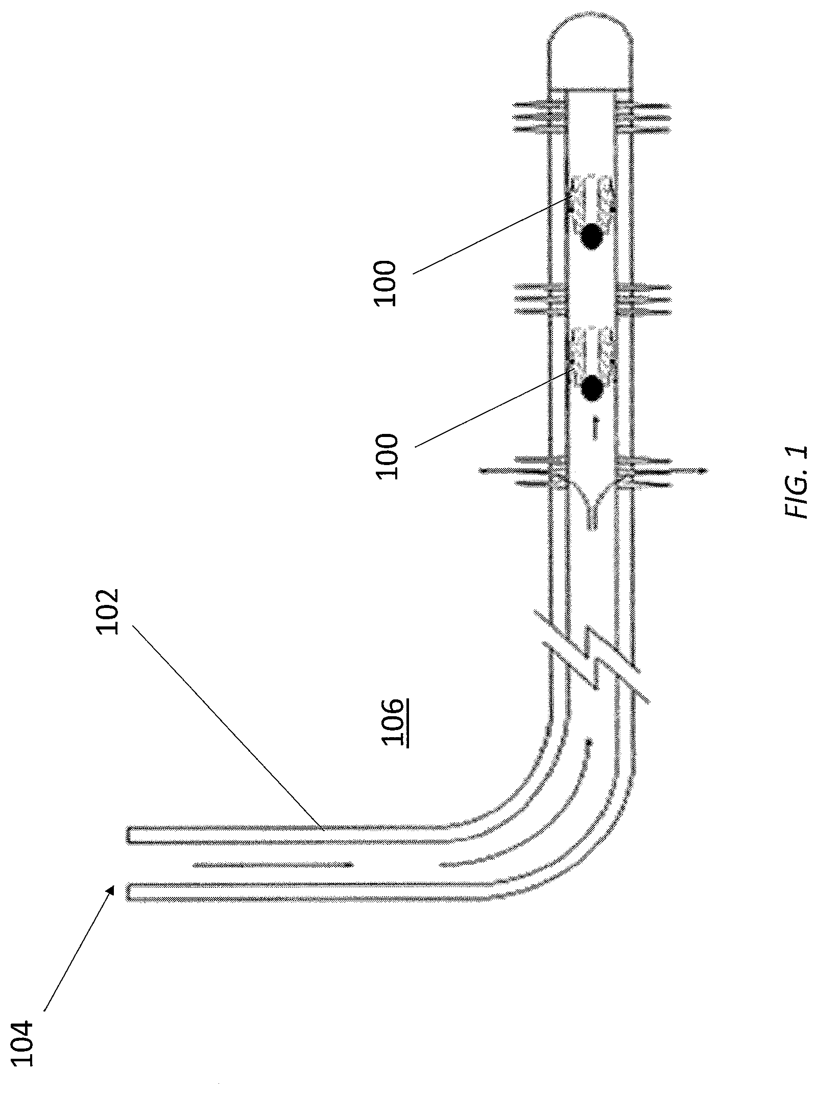
[0010] FIG. 1 illustrates a cutaway view of two exemplary frac plugs set in a tubular section disposed in a wellbore formed in a subterranean formation, according to one or more embodiments disclosed.
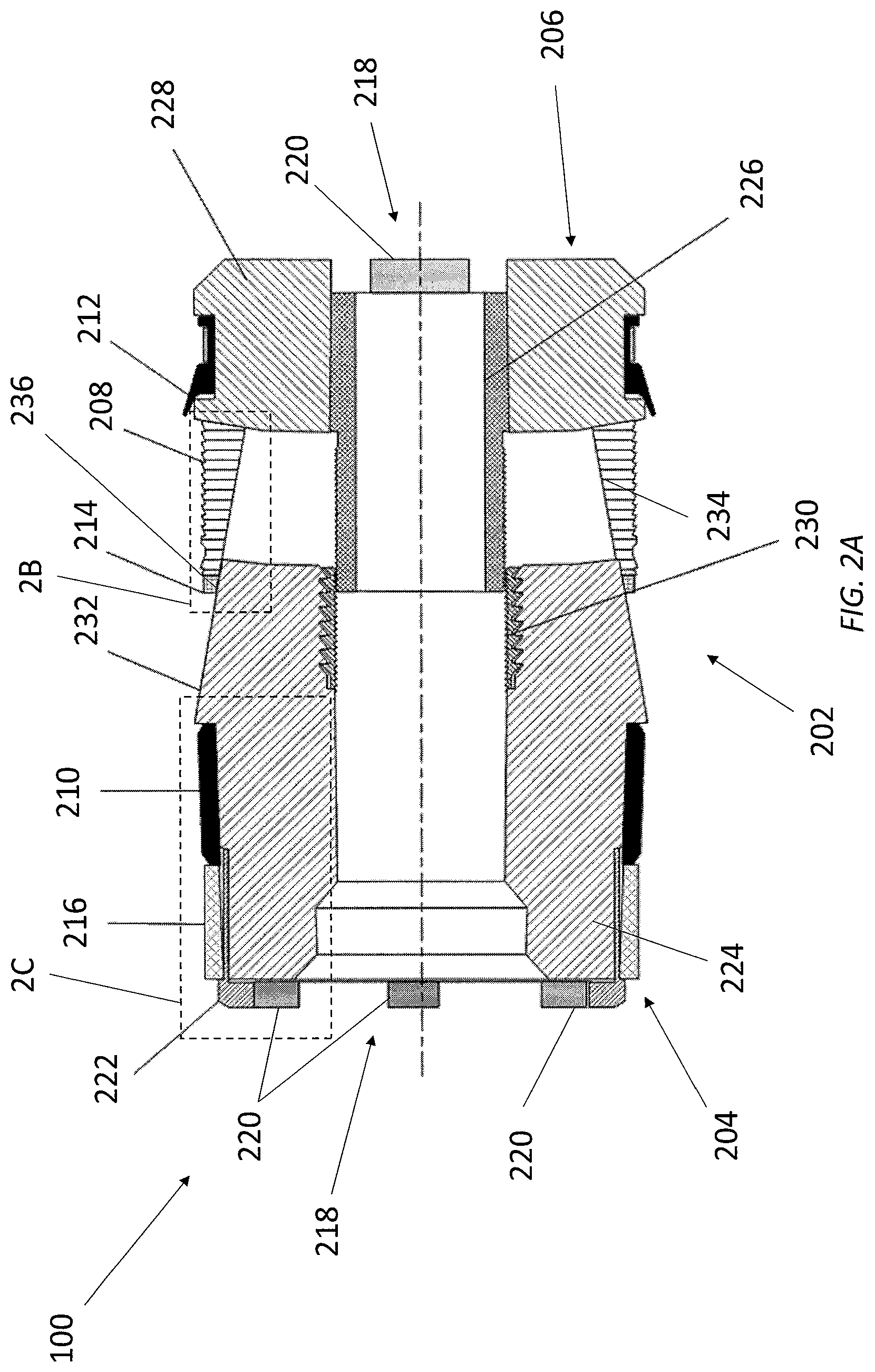
[0011] FIG. 2A illustrates a cross-sectional view of one of the frac plugs of FIG. 1.
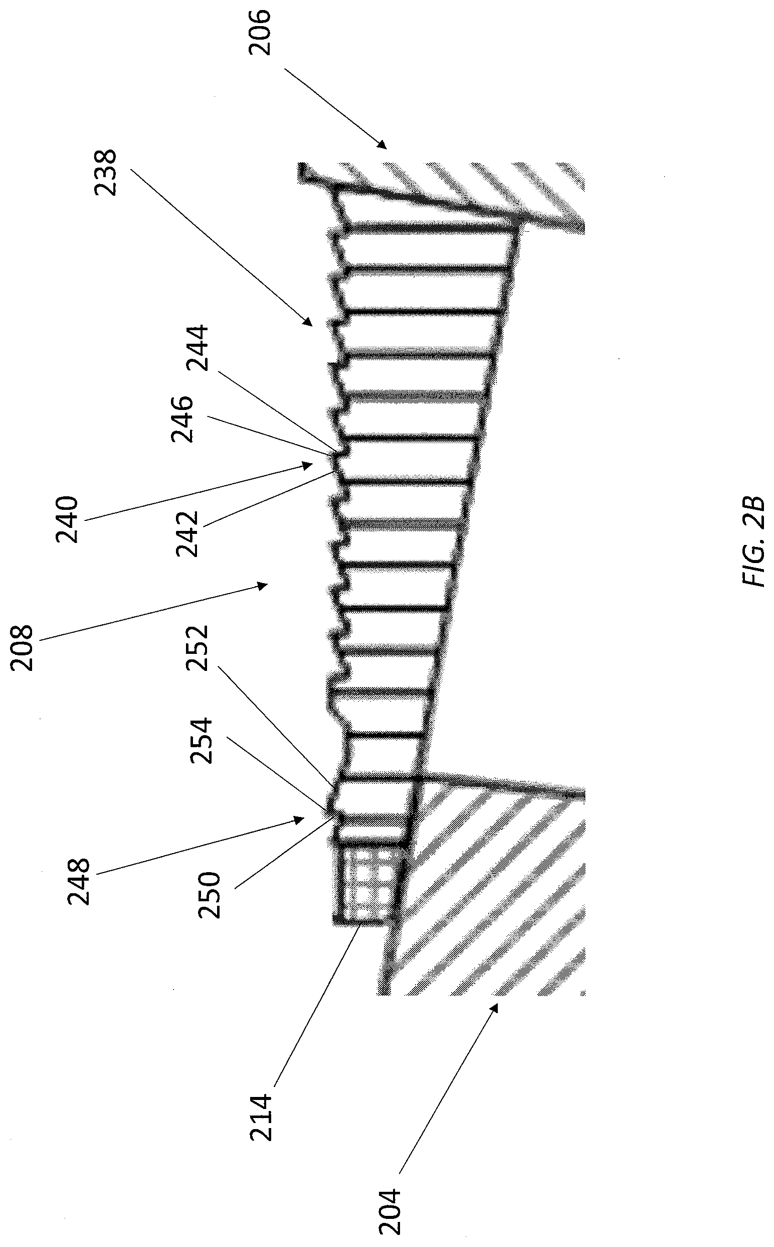
[0012] FIG. 2B illustrates an enlarged view of the portion of the frac plug indicated by the detail labeled 2B of FIG. 2A.
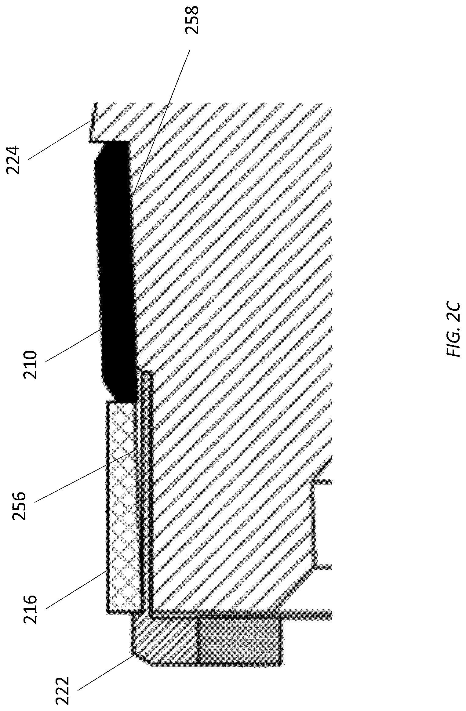
[0013] FIG. 2C illustrates an enlarged view of the portion of the frac plug indicated by the detail labeled 2C of FIG. 2A.
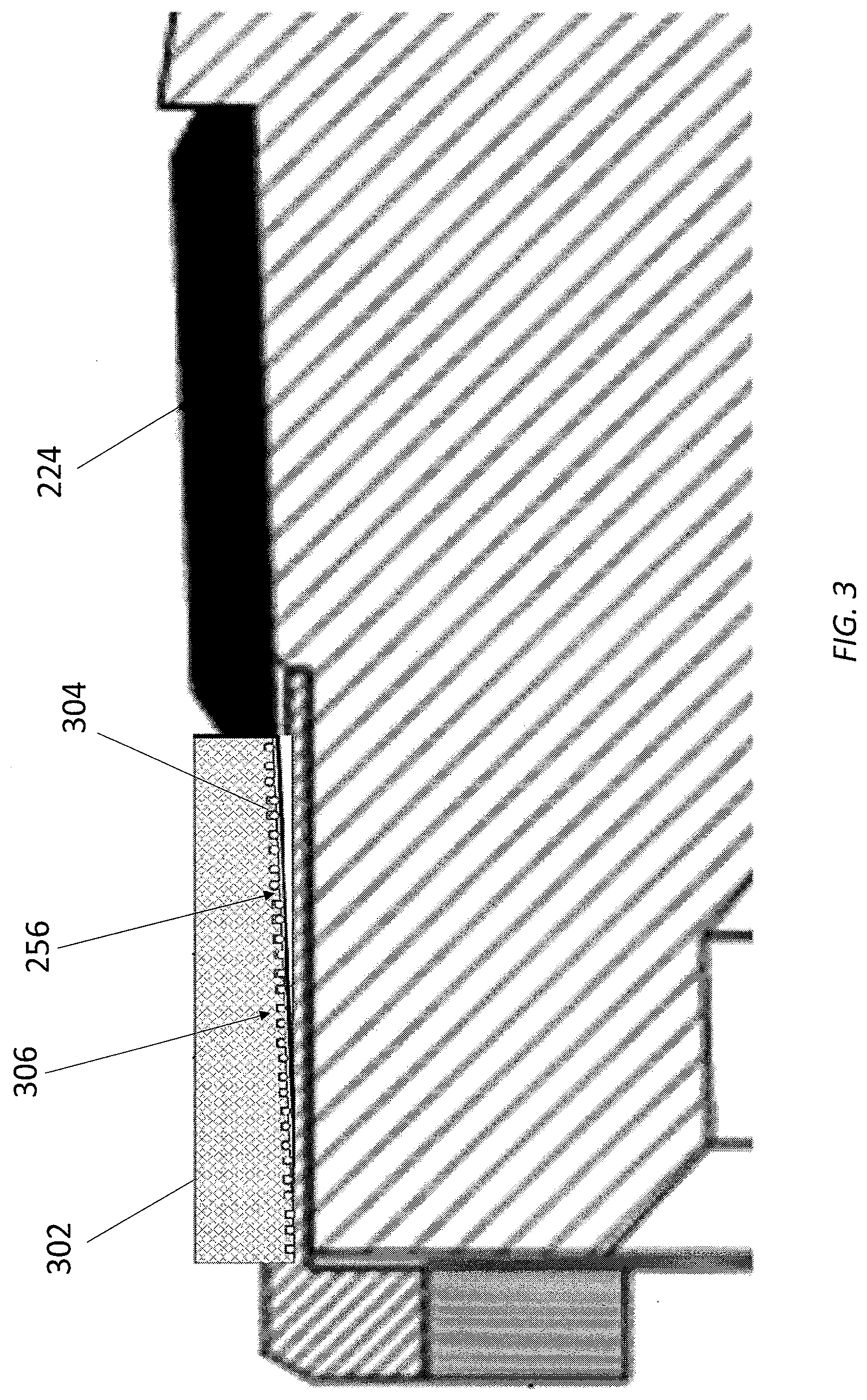
[0014] FIG. 3 illustrates a cross-sectional view of an exemplary compression ring, according to one or more embodiments disclosed.
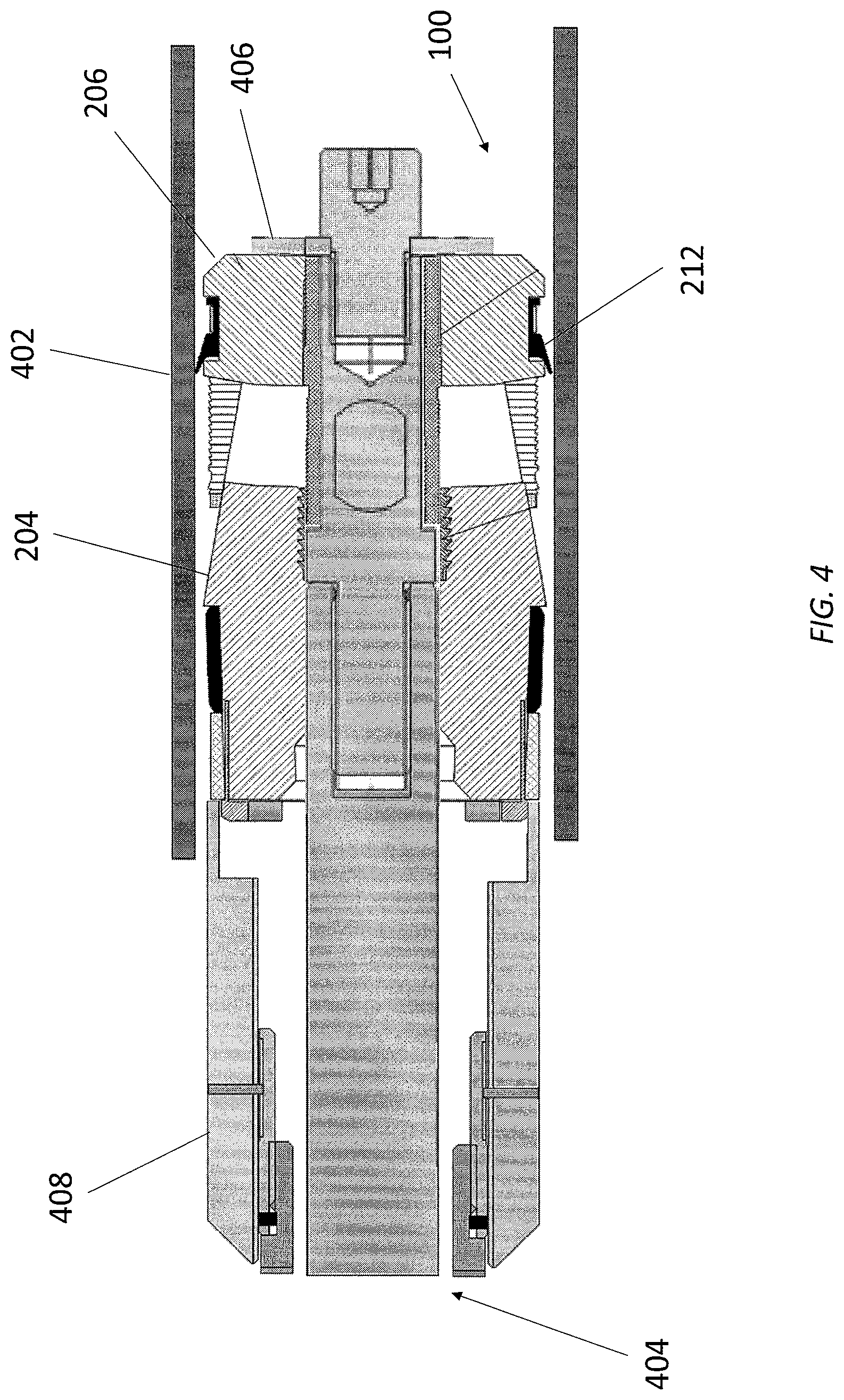
[0015] FIG. 4 illustrates the frac plug of FIGS. 2A-2C being run into the wellbore.
[0016] FIG. 5 illustrates the frac plug of FIG. 4 as the frac plug is being set in position within the tubular section.
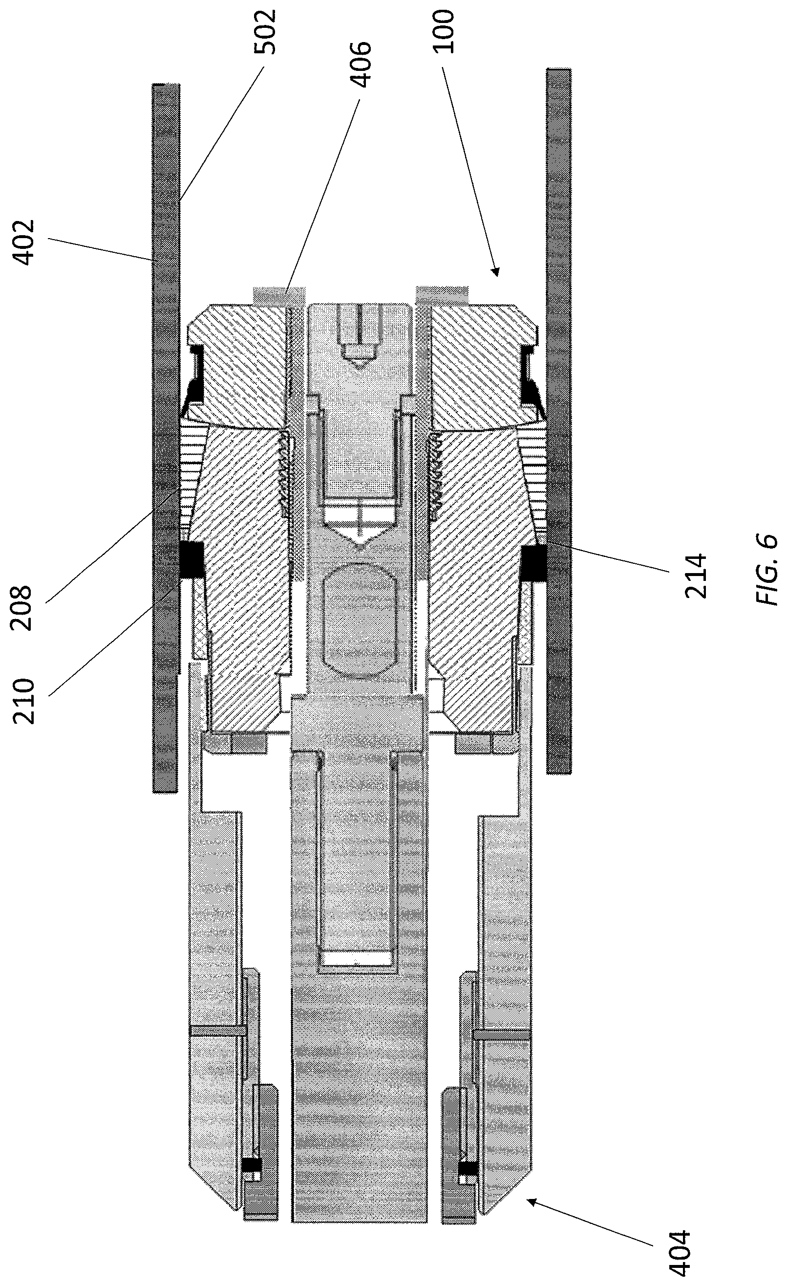
[0017] FIG. 6 illustrates the frac plug of FIG. 5 in the set position.
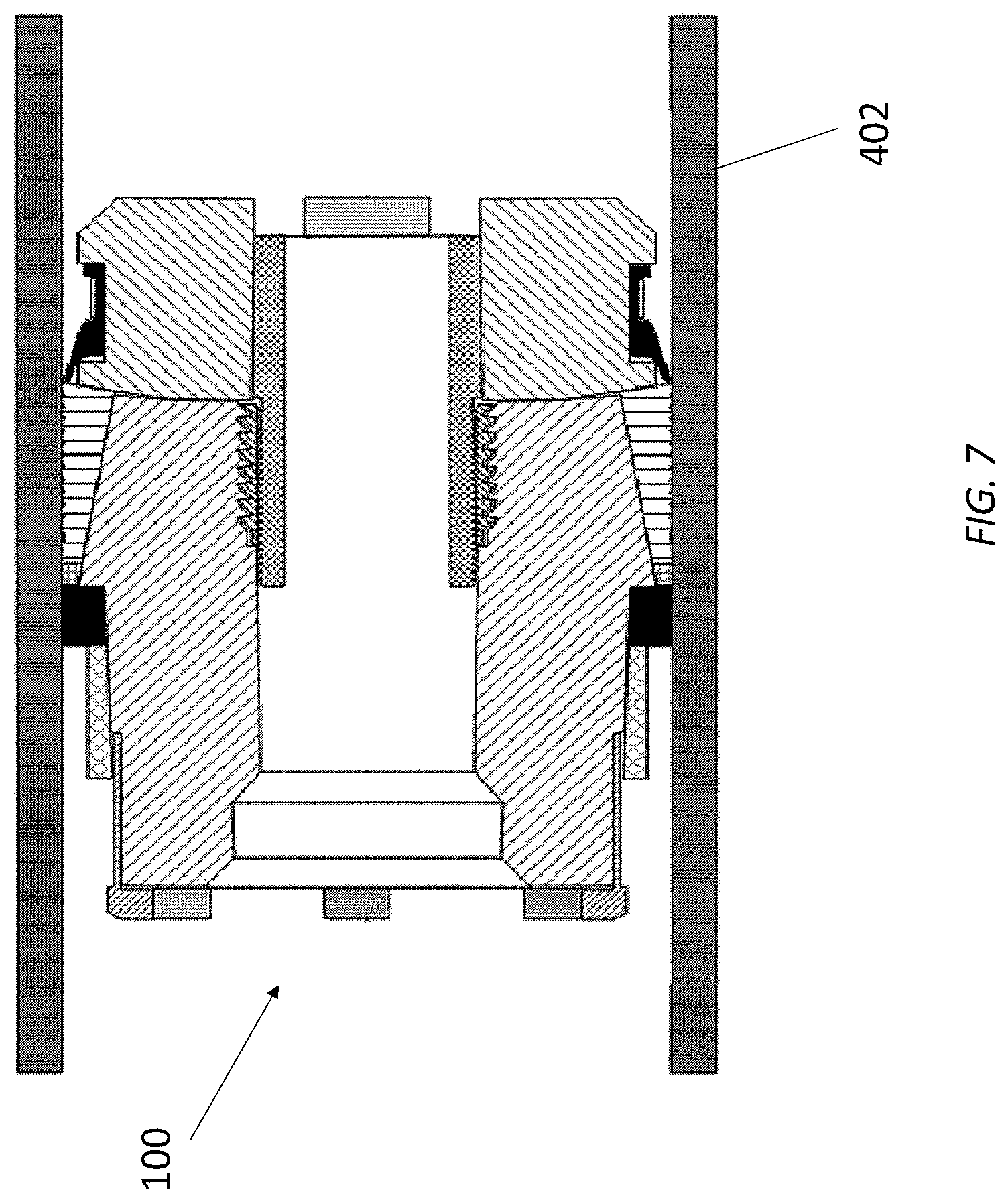
[0018] FIG. 7 illustrates the running tool being retracted from the frac plug of FIG. 6.
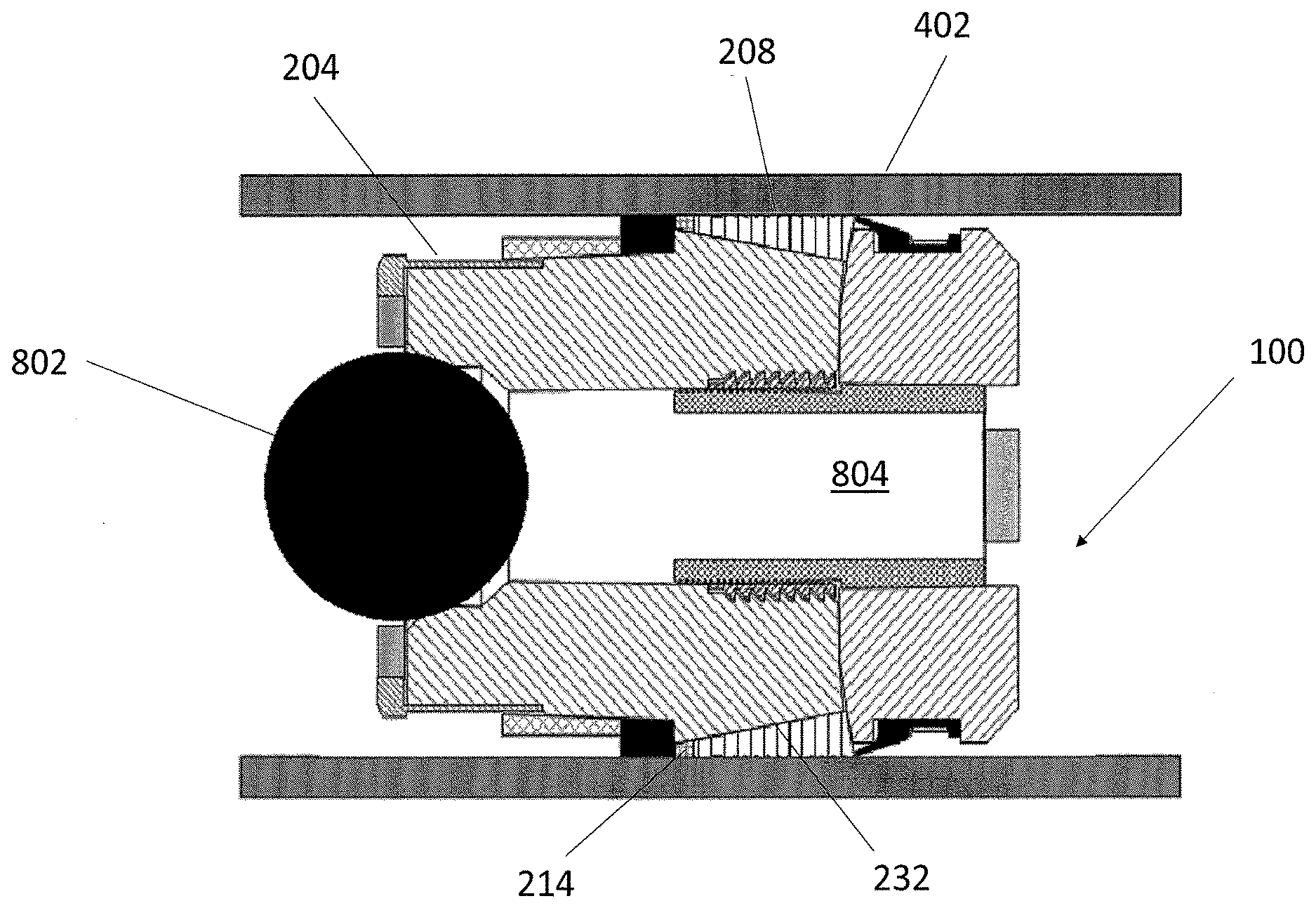
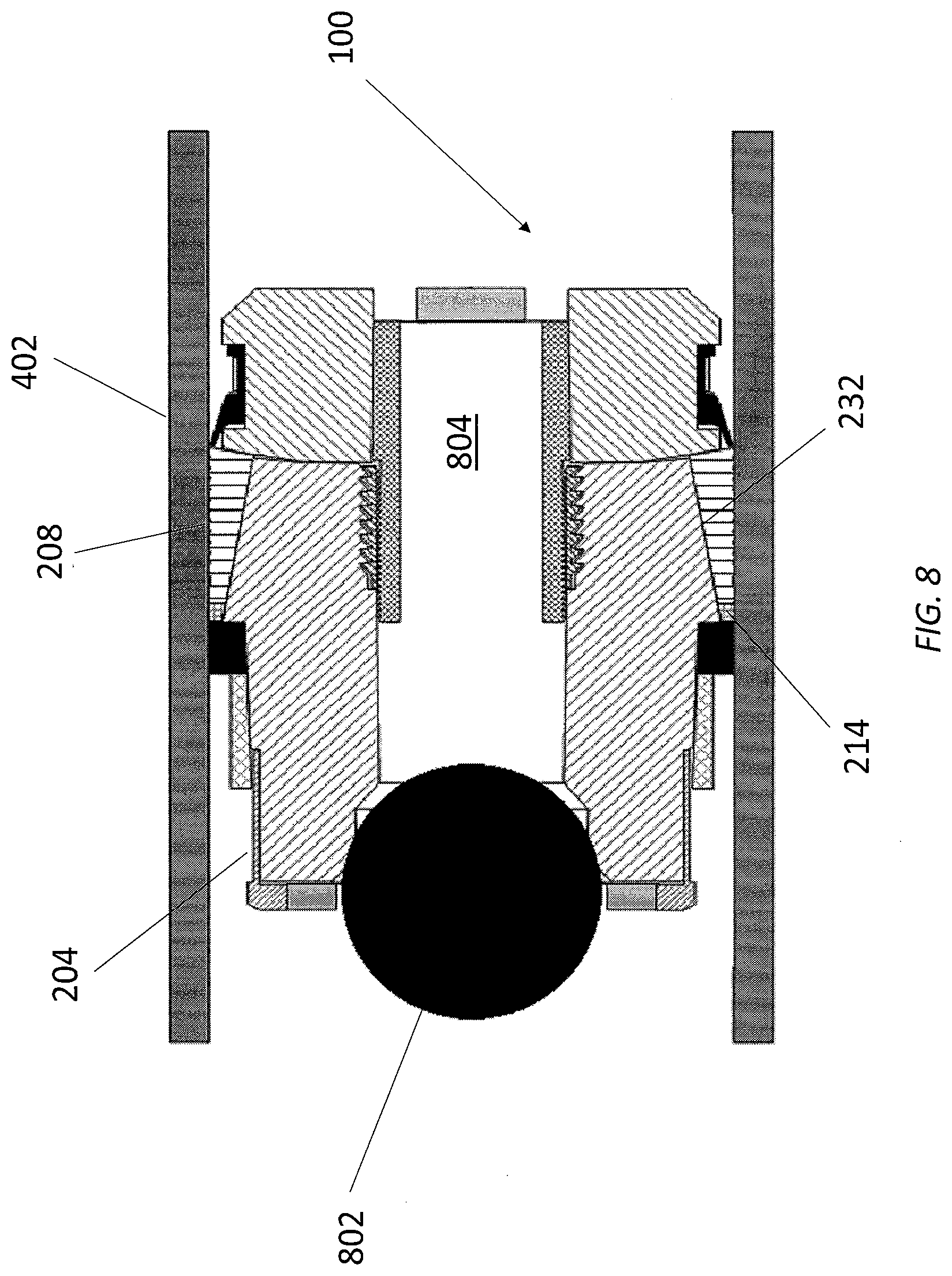
[0019] FIG. 8 illustrates the frac plug of FIG. 7 sealed with a sealing ball.
DETAILED DESCRIPTION
[0020] It is to be understood that the following disclosure describes several exemplary embodiments for implementing different features, structures, or functions of the invention. Exemplary embodiments of components, arrangements, and configurations are described below to simplify the present disclosure; however, these exemplary embodiments are provided merely as examples and are not intended to limit the scope of the invention. Additionally, the present disclosure may repeat reference numerals and/or letters in the various exemplary embodiments and across the Figures provided herein. This repetition is for the purpose of simplicity and clarity and does not in itself dictate a relationship between the various exemplary embodiments and/or configurations discussed in the various Figures. Moreover, the formation of a first feature over or on a second feature in the description that follows may include embodiments in which the first and second features are formed in direct contact, and may also include embodiments in which additional features may be formed interposing the first and second features, such that the first and second features may not be in direct contact. Finally, the exemplary embodiments presented below may be combined in any combination of ways, i.e., any element from one exemplary embodiment may be used in any other exemplary embodiment, without departing from the scope of the disclosure.
[0021] Additionally, certain terms are used throughout the following description and claims to refer to particular components. As one skilled in the art will appreciate, various entities may refer to the same component by different names, and as such, the naming convention for the elements described herein is not intended to limit the scope of the invention, unless otherwise specifically defined herein. Further, the naming convention used herein is not intended to distinguish between components that differ in name but not function. Additionally, in the following discussion and in the claims, the terms "including" and "comprising" are used in an open-ended fashion, and thus should be interpreted to mean "including, but not limited to." All numerical values in this disclosure may be exact or approximate values unless otherwise specifically stated. Accordingly, various embodiments of the disclosure may deviate from the numbers, values, and ranges disclosed herein without departing from the intended scope. Furthermore, as it is used in the claims or specification, the term "or" is intended to encompass both exclusive and inclusive cases, i.e., "A or B" is intended to be synonymous with "at least one of A and B," unless otherwise expressly specified herein.
[0022] Unless otherwise specified, use of the terms "up," "upper," "upward," "uphole," or other like terms shall be construed as generally toward the surface of the formation or the surface of a body of water; likewise, use of "down," "lower," "downward," "downhole," or other like terms shall be construed as generally away from the surface of the formation or the surface of a body of water, regardless of the wellbore orientation. Use of any one or more of the foregoing terms shall not be construed as denoting positions along a perfectly vertical axis.
[0023] FIG. 1 illustrates a cutaway view of two exemplary frac plugs 100 set in a tubular 102 disposed in a wellbore 104 formed in a subterranean formation 106, according to one or more embodiments disclosed. The wellbore 104 may be formed in the subterranean formation 106 via any conventional drilling means and is utilized for the retrieval of hydrocarbons therefrom. As illustrated, at least a portion of the wellbore 104 is oriented in a horizontal direction in the subterranean formation 106; however, embodiments in which the wellbore 104 is oriented in a convention vertical direction are contemplated herein, and the depiction of the wellbore 104 in a horizontal or vertical direction is not to be construed as limiting the wellbore 104 to any particular configuration. Accordingly, in some embodiments, the wellbore 104 may extend into the subterranean formation 106 in a vertical direction, thereby having a vertical wellbore portion, and may deviate at any angle from the vertical wellbore portion, thereby having a deviated or horizontal wellbore portion. Thus, the wellbore 104 may be or include portions that may be vertical, horizontal, deviated, and/or curved.
[0024] The wellbore 104 may be in fluid communication with the surface via a rig (not shown) and/or other associated components positioned on the surface around the wellbore 104. The rig may be a drilling rig or a workover rig, and may include a derrick and a rig floor. The frac plugs 100 may be delivered to a predetermined depth and positioned in the wellbore 104 via the rig to perform a part of a particular servicing operation such as, for example, isolating a section of the tubular 102 to allow fracturing of the subterranean formation 106.
[0025] FIG. 2A illustrates a cross-sectional view of one of the frac plugs 100 of FIG. 1. The frac plug 100 may include a plug body 202 that includes a first sub 204 and a second sub 206. Alternative embodiments of the frac plug 100 may instead include a plug body 202 having a single sub. The frac plug 100 may further include a slip 208, a sealing element 210, a pump down ring 212, a back-up ring 214, and a compression ring 216. In at least one embodiment, the external axial end portions 218 of the frac plug 100 may include circumferentially spaced, axial protrusions 220, or "castellations", extending from the frac plug 100. Other embodiments of the frac plug 100 may omit the castellations 220 from one or both of the external axial end portions 218 of the frac plug 100. The castellated axial end portions 218 are used in stacking multiple frac plugs 100 in a manner known in the art in some embodiments.
[0026] As shown in the exemplary embodiment, a cap 222 may be coupled to a main body 224 of the first sub 204. The cap 222 may be coupled to the main body 224 using adhesives, a threaded connection, or both. Still other mechanisms for coupling the cap 222 and the main body 224, such as bonding and mechanical fasteners, may be used in alternative embodiments. In other embodiments, the cap 222 may be omitted.
[0027] In one embodiment, the cap 222 may be a metal casting and the main body 224 may be a resin and fiber composite; however other suitable composites known in the art may be used. In some embodiments, the main body 224 may be cast, machined, or formed from a powdered metal. Additionally, in other embodiments, the cap 222 may be machined, formed from a powdered metal, or made of a composite material.
[0028] The second sub 206 may include a core 226 and an outer sleeve 228, as shown in the exemplary embodiment. The core 226 may be bonded, threadably engaged, or coupled to the outer sleeve 228 using the methods described above. In some embodiments, the core may be cast, machined, or formed from a powdered metal and the outer sleeve may be made of a composite material. In another embodiment, the second sub 206 may be a single component that is cast, machined, formed from powdered metal, or formed from a composite material. When assembled, the core 226 of the second sub 206 may be partially disposed within the main body 224 of the first sub 204.
[0029] The frac plug 100 may also include a threaded lock ring 230 that couples the first sub 204 to the second sub 206. In one embodiment, the lock ring 230 may be a C-ring type lock ring that includes a gap. In other embodiments, the lock ring 230 may be continuous. In a further embodiment of the frac plug 100, the first sub 204 may be threadably engaged with the second sub 206 without the use of a lock ring 230.
[0030] The slip 208 and back-up ring 214 may be positioned between the first and second subs 204, 206 of the frac plug 100, with the back-up ring 214 positioned adjacent to the first sub 204 and the slip 208. A portion of the outer surface 232 of the first sub 204 may be tapered, as shown in FIG. 2A. The slip 208, the back-up ring 214, or both may include a tapered inner surface 234, 236 that contacts the tapered outer surface 232 of the first sub 204.
[0031] In one embodiment, the slip 208 may be made of a powdered metal and the back-up ring 214 may be made of brass. In another embodiment, the slip 208 may be a composite material, cast iron, or any other material known in the art that is suitable for a slip 208. Additionally, in one or more embodiments, the back-up ring 214 may be made of titanium or another ductile metal that will allow the back-up ring 214 to expand without fracturing.
[0032] FIG. 2B illustrates an enlarged view of the portion of the frac plug 100 indicated by the detail labeled 2B of FIG. 2A. As shown in FIG. 2B, the back-up ring 214 of the frac plug 100 may have a trapezoidal cross-section. The slip 208 may include a left-hand thread profile 238. Each thread 240 (only one indicated) of the left-hand thread profile 238 may include a first flank 242 (only one indicated) that is longer than a second flank 244 (only one indicated), angling the crest 246 (only one indicated) of each thread 240 towards the second sub 206. Additionally, a portion of the slip 208 adjacent to the back-up ring 214 may define one or more threads 248. Each thread 248 may include a first flank 250 that is shorter than a second flank 252, angling the crest 254 of each thread 248 towards the first sub 204. In one embodiment, the slip 208 may include a second thread (not shown) that has a larger pitch, a larger pitch diameter, or both a larger pitch and a larger pitch diameter than the other thread or threads 248 that have crests 254 angled towards the first sub 204.
[0033] Other embodiments of the slip 208 may include threads 248 that have a pitch, a pitch diameter, or both a pitch and a pitch diameter that are the same size, or a different thread may have a larger pitch, a larger pitch diameter, or both a larger pitch and a larger pitch diameter than the other thread or threads 248. In another embodiment, the one or more threads 248 may be replaced by teeth (not shown) having points (not shown) that angle towards the first sub 204. Further embodiments of the slip 208 may include a left-hand thread profile 238, one or more threads 248, or both a left-hand thread profile 238 and one or more threads 248 that have crests 246, 254 that are generally perpendicular to the outer surface of the slip.
[0034] Referring now to FIG. 2C, FIG. 2C illustrates an enlarged view of the portion of the frac plug 100 indicated by the detail labeled 2C of FIG. 2A. As shown in FIG. 2C, the compression ring 216 may be retained by the cap 222 and, in turn, retain the sealing element 210 in position adjacent to the main body 224. This arrangement allows the sealing element 210 to be compressed independently of the slip 208. In another embodiment, the cap 222 may be omitted and friction may retain the compression ring 216 on the first sub 204. The compression ring 216 may be made of a composite material that can expand without failure. In other embodiments, the compression ring 216 may be a ductile metal, such as those described above in relation to the back-up ring 214, which can expand without failure.
[0035] The compression ring 216 may further include a tapered inner surface 256, as shown in the exemplary embodiment. Additionally, a portion 258 of the main body 224 may be tapered. In at least one embodiment, the taper of the inner surface 256 of the compression ring 216 and the portion 258 of the main body 224 may be about 2.degree.. In other embodiments, the taper may be omitted from either the compression ring 216 or the main body 224.
[0036] FIG. 3 illustrates a cross-sectional view of an exemplary compression ring 302, according to one or more embodiments. The compression ring 302 in FIG. 3 is alternative to the compression ring 216 shown in FIGS. 2A-2C, and may be used in place of compression ring 216 in frac plug 100. Accordingly, like numerals indicate like elements and therefore will not be described again in detail except where material to the present embodiment.
[0037] As shown in FIG. 3, the compression ring 302 may further include a material that is set into the inner surface 256 to increase friction between the compression ring 302 and the main body 224. In one embodiment, the material may be a plurality of quartz or ceramic beads 304 (only one indicated). In other embodiments, a coating (not shown) may be applied to the inner surface 256 to increase the friction. In another embodiment, the compression ring 302 may include a thread pattern 306 or grooves (not shown) defined in the inner surface 256. In additional embodiments, the beads 304 may be set into one or more of the grooves or one or more threads of the thread pattern 306 to increase the friction.
[0038] FIGS. 4-8 illustrate the installation of the frac plug 100 of FIGS. 1 and 2A-2C. Initially, the frac plug 100 is positioned within the tubular section 402 using a running tool 404 that extends through the frac plug 100, as shown in FIG. 4. The frac plug 100 is retained on the running tool 404 by a shear ring 406 configured to break at a predetermined load and a cylindrical retainer 408. The shear ring 406 may be positioned adjacent to the second sub 206 and the cylindrical retainer 408 may be positioned adjacent to the first sub 204. The process of positioning the frac plug 100 within the tubular section 402 may be aided by the pump down ring 212, which helps move the frac plug 100 into position within the tubular section 402. Once the frac plug 100 reaches the desired location, the running tool 404 begins to compress the frac plug 100 by pulling the shear ring 406 towards the cylindrical retainer 408 and pushing the cylindrical retainer 408 towards the shear ring 406.
[0039] As shown in FIG. 5, the tapered surface 232 of the first sub 204 may radially expand the slip 208 and back-up ring 214 as the frac plug 100 is compressed. In some embodiments, this expansion may cause the slip 208 to fracture along longitudinal grooves (not shown), creating a plurality of slip segments (not shown). In other embodiments, the longitudinal grooves in the slip 208 may allow the slip 208 to expand without fracturing or the longitudinal grooves may be omitted. As the back-up ring 214 is made of a ductile material, the back-up ring 214 expands without fracturing as it moves along the tapered surface 232.
[0040] As the frac plug 100 is compressed, the one or more threads 248 of the slip 208 that are facing the first sub 204 contact the tubular section 402. The one or more threads 248 may engage or "bite" into the inner surface 502 of tubular section 402, preventing further movement of the second sub 206 towards the first sub 204. Since the frac plug 100 is still being compressed by the running tool 404, the cylindrical retainer 408 will continue to push the first sub 204 towards the second sub 206. This movement allows the slip 208 and back-up ring 214 to continue to move along the tapered surface 232 of the first sub 204. The continued expansion of the slip 208 allows the left-hand threads 240 of the slip 208 to engage with the inner surface 502 tubular section 402, preventing movement of the slip 208 away from the first sub 204 and further retaining the frac plug 100 in position.
[0041] Additionally, the cylindrical retainer 408 may shift the compression ring 216 along the cap 222 and the main body 224 as the frac plug 100 is compressed. The taper on the compression ring 216, the main body 224, or both causes this movement to expand the compression ring 216 as it travels along the cap 222 and the main body 224. The movement of the compression ring 216 also compresses the sealing element 210 and creates a seal between the frac plug 100 and the tubular section 402. Further, the friction between the compression ring 216 and the main body 224 prevents movement of the compression ring 216 away sealing element 210, maintaining the seal between the first sub 204, the sealing element 210, and the tubular section 402.
[0042] The interface between the lock ring 230 and second sub 206 may have a ratcheting effect, where the external threads of the second sub 206 slide over the internal threads of the lock ring 230 in one direction, but are restricted from moving in the opposite direction by the internal threads of the lock ring 230. Accordingly, the ratcheting effect may prevent decompression of the frac plug 100.
[0043] In the exemplary embodiment, the compression ring 216 and sealing element 210 are both circumferentially disposed about the first sub 204 and separated from the slip 208 by the main body 224. This allows the compressive force applied by the running tool 404 to independently act on the compression ring 216 and the ratcheting interface between the lock ring 230 and the second sub 206. This arrangement allows the frac plug 100 to continue to compress even if one of the interfaces reaches full compression before the other interface, ensuring the frac plug 100 is fully set within the tubular section 402.
[0044] As shown in FIG. 6, the slip 208 may engage with the inner surface 502 of the tubular section 402 when the frac plug 100 is set, securing the frac plug 100 in place. Additionally, the back-up ring 214, having expanded into the position shown in FIG. 6, contacts the tubular section 402 and may prevent extrusion of the sealing element 210. Once the frac plug 100 is set in position, the shear ring 406 breaks when the predetermined load is reached. The running tool 404 is then tripped out of the tubular section 402.
[0045] Once the running tool 404 is removed from the frac plug 100 and tubular section 402, as shown in FIG. 7, a sealing ball 802 is dropped down the tubular section 402. The sealing ball 802 seats against the first sub 204, as shown in FIG. 8, sealing the bore 804 of the frac plug 100. The force of the sealing ball 802 against the first sub 204 of the frac plug 100 may further secure the frac plug 100 in place by shifting the back-up ring 214 and slip 208 further along the tapered surface 232 of the first sub 204.
[0046] The foregoing has outlined features of several embodiments so that those skilled in the art may better understand the present disclosure. Those skilled in the art should appreciate that they may readily use the present disclosure as a basis for designing or modifying other processes and structures for carrying out the same purposes and/or achieving the same advantages of the embodiments introduced herein. Those skilled in the art should also realize that such equivalent constructions do not depart from the spirit and scope of the present disclosure, and that they may make various changes, substitutions, and alterations herein without departing from the spirit and scope of the present disclosure.
* * * * *
D00000
D00001
D00002
D00003
D00004
D00005
D00006
D00007
D00008
D00009
D00010
XML
uspto.report is an independent third-party trademark research tool that is not affiliated, endorsed, or sponsored by the United States Patent and Trademark Office (USPTO) or any other governmental organization. The information provided by uspto.report is based on publicly available data at the time of writing and is intended for informational purposes only.
While we strive to provide accurate and up-to-date information, we do not guarantee the accuracy, completeness, reliability, or suitability of the information displayed on this site. The use of this site is at your own risk. Any reliance you place on such information is therefore strictly at your own risk.
All official trademark data, including owner information, should be verified by visiting the official USPTO website at www.uspto.gov. This site is not intended to replace professional legal advice and should not be used as a substitute for consulting with a legal professional who is knowledgeable about trademark law.