Water Saving Device
LIANG; YOU-YU ; et al.
U.S. patent application number 16/506769 was filed with the patent office on 2020-02-13 for water saving device. The applicant listed for this patent is Runner (Xiamen) Corp.. Invention is credited to SHENG-CHAO DAI, KAI LI, YOU-YU LIANG, CAN-KUN WU.
| Application Number | 20200048876 16/506769 |
| Document ID | / |
| Family ID | 67047283 |
| Filed Date | 2020-02-13 |


| United States Patent Application | 20200048876 |
| Kind Code | A1 |
| LIANG; YOU-YU ; et al. | February 13, 2020 |
WATER SAVING DEVICE
Abstract
A water saving device is disclosed, which comprises a base having a water flow channel, a throttle ring and a support seat made of an elastic material, and a capacity space is formed in the base, and the support seat is disposed in the capacity space. An annular channel is formed between the support seat and the base. The water channel is in communication with the annular channel. The throttle ring is disposed in the annular channel. When the water pressure is increased to a certain extent, the throttle ring is deformed, and the cross-sectional area of the water flow channel is reduced. The water saving device can effectively prevent the throttle ring from shifting or falling off, and it also has good structural strength and stability that is not easily deformed or broken by external force.
| Inventors: | LIANG; YOU-YU; (Xiamen, CN) ; WU; CAN-KUN; (Xiamen, CN) ; LI; KAI; (Xiamen, CN) ; DAI; SHENG-CHAO; (Xiamen, CN) | ||||||||||
| Applicant: |
|
||||||||||
|---|---|---|---|---|---|---|---|---|---|---|---|
| Family ID: | 67047283 | ||||||||||
| Appl. No.: | 16/506769 | ||||||||||
| Filed: | July 9, 2019 |
| Current U.S. Class: | 1/1 |
| Current CPC Class: | G05D 7/012 20130101; E03C 2001/026 20130101; E03C 1/02 20130101 |
| International Class: | E03C 1/02 20060101 E03C001/02 |
Foreign Application Data
| Date | Code | Application Number |
|---|---|---|
| Aug 9, 2018 | CN | 201821280151.7 |
Claims
1. A water saving device, comprising: a base having a water flow channel; and a throttle ring and a support seat made of an elastic material, wherein a capacity space is formed in the base, the support seat is disposed in the capacity space, an annular channel is formed between the support seat and the base, the water flow channel is in communication with the annular channel. and the throttle ring is disposed in the annular channel, when the water pressure is increased to a certain extent, the throttle ring is deformed, so that the cross-sectional area of the water flow channel is reduced.
2. The water saving device as claimed in claim 1, wherein a groove is disposed in a middle portion of the support seat.
3. The water saving device as claimed in claim 1, wherein the support seat is of a circular ring shape.
4. The water saving device as claimed in claim 1, wherein the support seat includes a body and an extension portion, and the extension portion has an oblique angle with respect to an outer circumference of the body
5. The water saving device as claimed in claim 4, wherein the oblique angle is an obtuse angle.
6. The water saving device as claimed in claim 1, wherein an annular boss is disposed in the seat relative to a position of the throttle ring.
7. The water saving device as claimed in claim 6, wherein a plurality of concave-convex structures are uniformly distributed around the annular boss.
8. The water saving device as claimed in claim 1, wherein a plurality of support ribs are disposed and spaced apart between the base and the support base.
9. The water saving device as claimed in claim 1, wherein the support seat is integrally formed with the base.
Description
BACKGROUND OF THE INVENTION
Field of the Invention
[0001] The present invention relates to a water related device, and in particular to a water saving device.
The Prior Arts
[0002] Water shortage is an important issue of global concern, therefore, water conservation in daily life is an environmental issue that needs to be encouraged and promoted. However, the water saving device in the existing market has a problem that the elastic deformation ring inside the water saving device-tends to be easily washed away by water flow or gas flow. In addition, some parts within the water saving device are weak and can be easily crushed or deformed during installation.
SUMMARY OF THE INVENTION
[0003] In view of the problems and drawbacks of the prior art, the present invention provides a water saving device.
[0004] To achieve the above objective, the technical means of the present invention is that a water saving device, which comprises a base having a water flow channel, a throttle ring and a support seat made of an elastic material, and a capacity space is formed in the base, and the support seat is disposed in the capacity space. The annular channel is formed between the support seat and the base. The water channel is in communication with the annular channel. The throttle ring is disposed in the annular channel. When the water pressure is increased to a certain extent, the throttle ring is deformed, and the cross-sectional area of the water flow channel is reduced.
[0005] Preferably, a groove is disposed in a middle portion of the support seat.
[0006] Preferably, the support seat is of a circular shape.
[0007] Preferably, the support seat includes a body and an extension portion, and the extension portion has an oblique angle relative to an outer circumference of the body.
[0008] Preferably, the oblique angle is an obtuse angle.
[0009] Preferably, an annular boss is disposed in the seat relative to the position of the throttle ring.
[0010] Preferably, a plurality of concave-convex structures are uniformly distributed-around the annular boss.
[0011] Preferably, a plurality of support ribs are disposed and spaced apart from between the base and the support seat.
[0012] Preferably, the support seat is integrally formed with the base.
[0013] The water saving device of the present invention can effectively prevent the throttle ring from shifting or falling off, has good structural strength and stability, and is not easily deformed or broken by external force.
BRIEF DESCRIPTION OF THE DRAWINGS
[0014] The related drawings in connection with the detailed descriptions of the present invention to be made later are described briefly as follows, in which:
[0015] FIG. 1 is a partial perspective view of the present invention;
[0016] FIG. 2 is a cross-sectional view of the present invention; and
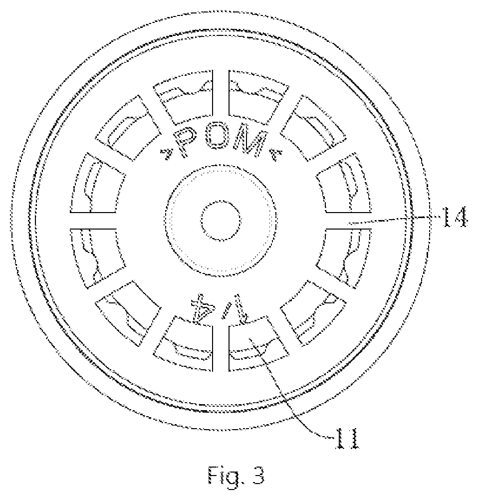
[0017] FIG. 3 is a top view of the present invention.
DETAILED DESCRIPTION OF THE PREFERRED EMBODIMENT
[0018] The purpose, construction, features, functions and advantages of the present invention can be appreciated and understood more thoroughly through the following detailed descriptions with reference to the attached drawings.
[0019] In the following, an embodiment is used to describe the various details of the present invention. However, it does not mean that this embodiment represents all the embodiments of the present invention. Other embodiments can be envisaged by people familiar with this field, and thus they all fall into the scope of the present invention.
[0020] Refer to FIGS. 1 to 3, the present invention discloses a water saving device, which includes a base 1 having a water flow channel 11, and a throttle ring 2 and a support seat 3 made of an elastic material. Preferably, the support seat 3 is integrally formed with the base 1 to enhance the stability of the structure. A capacity space 12 is formed in the base 1, and the support seat 3 is disposed in the capacity space 12. An annular channel 10 is formed between the support seat 3 and the base 1. The water flow channel 11 is in communication with the annular channel 10. Preferably, a groove 30 is disposed in a middle portion of the support seat 3. For example, as shown in FIG. 1, the support seat 3 is of an annular shape, and other shapes having grooves are can also be included in the consideration of the present invention. The disposing above makes the throttle ring 2 subject to pressure and deformation to be more balanced, and to have better control of the water volume. More preferably, the support seat 3 includes a body 31 and an extension portion 32 having an inclination angle .theta. relative to the outer circumference of the body 31. Preferably, the inclination angle .theta. is an obtuse angle. As a result, the support seat 3 having the groove 30 is combined with the extension portion 32 to form into an inverted structure. The extension portion 32 is a complete molding portion, which can effectively prevent the throttle ring 2 from shifting or falling off, and it also has good structural strength and stability that is not easily deformed or broken by external force. Besides, the throttle ring 2 is disposed in the annular channel 10, and when the water pressure is increased to a certain extent, the throttle ring 2 is deformed, and the cross-sectional area of the water flow channel 11 is reduced. Further, a plurality of support ribs 14 are disposed and spaced apart between the base 1 and the support base 3, and the support ribs 14 may be integrally formed with the base 1 and the support seat 3 to further strengthen the strength and stability of the structure.
[0021] Refer to FIG. 1, an annular boss 13 is disposed in the base 1 relative to the throttle ring 2, and a plurality of concave-convex structures 13a are uniformly distributed around the annular boss 13. The deformation of the throttle ring 2 is restricted by the annular boss 13 so that a certain flow amount can be reached. Preferably, the concave-convex structures 13a is a concave-convex structure having rounded corners and it could avoid unnecessary damages to the throttle ring 2 and makes the force of the throttle ring 2 to be more balanced.
[0022] The operation principle of the water saving device of the present invention will be described in detail below. When the water pressure is low, the water flows through the water channel 11, and the throttle ring 2 is not deformed, and the water flows normally in the water channel; when the water pressure is gradually increased, the water flow is increased in proportion to the water pressure. However, when the water pressure is increased to a certain extent, the throttle ring 2 is deformed under the water pressure to block part of the water flow channel 11, and the cross-sectional area of the water flow channel 11 is reduced. At this time, the water flow is no longer proportional to the water pressure, but it tends to be steady or have very slight rise or fall, in ultimately achieving the purpose of water saving.
[0023] The above detailed description of the preferred embodiment is intended to describe more clearly the characteristics and spirit of the present invention. However, the preferred embodiments disclosed above are not intended to be any restrictions to the scope of the present invention. Conversely, its purpose is to include the various changes and equivalent arrangements which are within the scope of the appended claims.
* * * * *
D00000
D00001
D00002
D00003
XML
uspto.report is an independent third-party trademark research tool that is not affiliated, endorsed, or sponsored by the United States Patent and Trademark Office (USPTO) or any other governmental organization. The information provided by uspto.report is based on publicly available data at the time of writing and is intended for informational purposes only.
While we strive to provide accurate and up-to-date information, we do not guarantee the accuracy, completeness, reliability, or suitability of the information displayed on this site. The use of this site is at your own risk. Any reliance you place on such information is therefore strictly at your own risk.
All official trademark data, including owner information, should be verified by visiting the official USPTO website at www.uspto.gov. This site is not intended to replace professional legal advice and should not be used as a substitute for consulting with a legal professional who is knowledgeable about trademark law.