Method For Operating An Apparatus For Additively Manufacturing Three-dimensional Objects
PETRATSCHEK; Andre ; et al.
U.S. patent application number 16/290945 was filed with the patent office on 2020-02-13 for method for operating an apparatus for additively manufacturing three-dimensional objects. This patent application is currently assigned to CONCEPT LASER GMBH. The applicant listed for this patent is CONCEPT LASER GMBH. Invention is credited to Benjamin GUNTHER, Andre PETRATSCHEK.
| Application Number | 20200047416 16/290945 |
| Document ID | / |
| Family ID | 63209323 |
| Filed Date | 2020-02-13 |


| United States Patent Application | 20200047416 |
| Kind Code | A1 |
| PETRATSCHEK; Andre ; et al. | February 13, 2020 |
METHOD FOR OPERATING AN APPARATUS FOR ADDITIVELY MANUFACTURING THREE-DIMENSIONAL OBJECTS
Abstract
Method for operating an apparatus (1) for additively manufacturing three-dimensional objects (2) by means of successive layerwise selective irradiation and consolidation of layers of a build material (3) which can be consolidated by means of an energy beam (4), wherein at least one energy beam (4) is guided along at least one track segment (13, 16-18) in the build plane based on irradiation data generated based on a space-filling curve.
| Inventors: | PETRATSCHEK; Andre; (Burgkunstadt, DE) ; GUNTHER; Benjamin; (Lichtenfels, DE) | ||||||||||
| Applicant: |
|
||||||||||
|---|---|---|---|---|---|---|---|---|---|---|---|
| Assignee: | CONCEPT LASER GMBH Lichtenfels DE |
||||||||||
| Family ID: | 63209323 | ||||||||||
| Appl. No.: | 16/290945 | ||||||||||
| Filed: | March 3, 2019 |
| Current U.S. Class: | 1/1 |
| Current CPC Class: | B22F 2201/11 20130101; B29C 64/371 20170801; B33Y 50/02 20141201; B29C 64/135 20170801; B29C 64/277 20170801; B22F 3/1055 20130101; B33Y 50/00 20141201; B29C 64/268 20170801; B29C 64/393 20170801; B22F 2003/1058 20130101; B29C 64/153 20170801; B22F 2003/1057 20130101; B29C 64/386 20170801; B33Y 10/00 20141201; B33Y 30/00 20141201 |
| International Class: | B29C 64/393 20060101 B29C064/393; B29C 64/277 20060101 B29C064/277; B22F 3/105 20060101 B22F003/105; B29C 64/153 20060101 B29C064/153; B29C 64/268 20060101 B29C064/268 |
Foreign Application Data
| Date | Code | Application Number |
|---|---|---|
| Aug 10, 2018 | EP | 18188567.4 |
Claims
1. Method for operating an apparatus (1) for additively manufacturing three-dimensional objects (2) by means of successive layerwise selective irradiation and consolidation of layers of a build material (3) which can be consolidated by means of an energy beam (4), characterized in that at least one energy beam (4) is guided along at least one track segment (13, 16-18) in the build plane based on irradiation data generated based on a space-filling curve.
2. Method according to claim 1, characterized by defining a track area (12) for at least one region (9) of at least one layer that is to be irradiated filling the track area (12) with at least one track segment (13, 16-18) based on a space-filling curve generating the intersection between the at least one region (9) and the track area (12).
3. Method according to claim 2, characterized by defining a start point (14) and an end point (15) for each track segment (16-18) based on the points of intersection between the track area (12) and the region (9) to be irradiated.
4. Method according to claim 3, characterized by connecting each end point (15) with a start point (14) of the following track segment (16-18) with respect to the direction defined by the space-filling curve.
5. Method according to claim 1, characterized in that as space-filling curve a Hilbert-curve and/or a Peano-curve and/or an H-tree and/or a Z-curve and/or an E-curve and/or a Sierpinski curve is used.
6. Method according to claim 1, characterized by generating irradiation data based on the space-filling curve for at least one region (9) to be irradiated dependent on at least one structure parameter of the region (9), in particular the size and/or the shape of the region (9).
7. Method according to claim 6, characterized by generating irradiation data based on the space-filling curve for at least one region (9) comprising a core region and/or at least one region (9) that is free of filigree structures.
8. Method according to claim 1, characterized by generating at least one track segment (13, 16-18) based on the space-filling curve with a defined track width of the at least one track segment (13, 16-18) dependent on a parameter of the energy beam (4), in particular a spot size.
9. Method according to claim 1, characterized by guiding the at least one energy beam (4) along the at least one track segment (13, 16-18) based on the space-filling curve, so as to generate a defined, in particular uniform, temperature distribution in the build material layer.
10. Method for generating irradiation data for an apparatus (1) for additively manufacturing three-dimensional objects (2) by means of successive layerwise selective irradiation and consolidation of layers of a build material (3) which can be consolidated by means of an energy beam (4), which irradiation data comprise at least one track segment (13, 16-18) along which the energy beam (4) is guided across a build plane, characterized in that at least one track segment (13, 16-18) of the irradiation data is generated based on a space-filling curve.
11. Control unit (10) for generating or receiving irradiation data, in particular for an apparatus (1) for additively manufacturing three-dimensional objects (2) by means of successive layerwise selective irradiation and consolidation of layers of a build material (3) which can be consolidated by means of an energy beam (4), which irradiation data comprise at least one track segment (13, 16-18) along which the energy beam (4) is guided across a build plane, characterized in that the control unit (10) is adapted to generate at least one track segment (13, 16-18) of the irradiation data based on a space-filling curve.
12. Apparatus (1) for additively manufacturing three-dimensional objects (2) by means of successive layerwise selective irradiation and consolidation of layers of a build material (3) which can be consolidated by means of an energy beam (4), which apparatus (1) comprises a control unit (10) adapted to generate or receive irradiation data, in particular a control unit (10) according to claim 11, which irradiation data comprise at least one track segment (13, 16-18) along which the energy beam (4) is guided across a build plane, characterized in that the control unit (10) is adapted to generate at least one track segment (13, 16-18) of the irradiation data based on a space-filling curve.
Description
[0001] The invention relates to a method for operating an apparatus for additively manufacturing three-dimensional objects by means of successive layerwise selective irradiation and consolidation of layers of a build material which can be consolidated by means of an energy beam.
[0002] Apparatuses for additively manufacturing three-dimensional objects and methods for operating the same are generally known from prior art. For example, it is possible to guide an energy beam, such as a laser beam or an electron beam across a build plane in which build material is arranged to be selectively irradiated. By successive layerwise selective irradiation and consolidation the three-dimensional object may be built.
[0003] Further, it is known from prior art that while operating the apparatus, in particular irradiating build material, the track segment along which the energy beam is guided across the build plane has significant effect on the object quality. Hence, the build material can be irradiated dependent on a so-called "irradiation strategy" that defines how a layer is to be irradiated, in particular the sequence in which the individual regions in a layer are irradiated, for example the track along which the energy beam is guided across the build plane. For example, the sequence in which different regions of the layer of build material are irradiated can have an effect on mechanical properties due to residual stress introduced by irradiating different regions at different times, as the different cooling behavior of the different regions may lead to thermal strains and mechanical stress in the object.
[0004] It is an object of the present invention to provide a method for operating an apparatus for additively manufacturing three-dimensional objects, wherein stress in the object can be reduced.
[0005] The object is inventively achieved by a method according to claim 1.
[0006] Advantageous embodiments of the invention are subject to the dependent claims.
[0007] The method described herein is a method for operating an apparatus for additively manufacturing three-dimensional objects, e.g. technical components, by means of successive selective layerwise consolidation of layers of a powdered build material ("build material") which can be consolidated by means of an energy beam, in particular a laser beam or an electron beam. A respective build material can be a metal, ceramic or polymer powder. A respective energy beam can be a laser beam or an electron beam. A respective apparatus can be an apparatus in which an application of build material and a consolidation of build material is performed separately, such as a selective laser sintering apparatus, a selective laser melting apparatus or a selective electron beam melting apparatus, for instance.
[0008] The apparatus may comprise a number of functional units which are used during its operation. Exemplary functional units are a process chamber, an irradiation device which is adapted to selectively irradiate a build material layer disposed in the process chamber with at least one energy beam, and a stream generating device which is adapted to generate a gaseous fluid stream at least partly streaming through the process chamber with given streaming properties, e.g. a given streaming profile, streaming velocity, etc. The gaseous fluid stream is capable of being charged with non-consolidated particulate build material, particularly smoke or smoke residues generated during operation of the apparatus, while streaming through the process chamber. The gaseous fluid stream is typically inert, i.e. typically a stream of an inert gas, e.g. argon, nitrogen, carbon dioxide, etc.
[0009] As described before, the invention relates to a method for operating apparatuses for additively manufacturing three-dimensional objects, which apparatuses comprise at least one irradiation device that is adapted to generate an energy beam. The energy beam can be guided across the build plane to selectively irradiate the build material arranged in the build plane. The invention is based on the idea that at least one energy beam is guided along at least one track segment in the build plane based on irradiation data that are generated based on a space-filling curve.
[0010] Thus, it is possible to (continuously) guide the energy beam along the at least one track segment across the build plane, which track segment is defined by a space-filling curve. Therefore, (different) thermal strains due to borders of regions in the build material that are irradiated at different times can be reduced, as the space-filling curve allows for continuously guiding the energy beam across the area that is to be irradiated. Another advantage of guiding the energy beam along the track segment defined by a space-filling curve is that the energy beam can continuously be guided along the track segment and there is no need for repositioning the energy beam to different starting points and end points, for example compared to a stripe wise irradiation or an island irradiation, respectively, the effort for repositioning the energy beam can be reduced significantly.
[0011] The term "space-filling curve" in the scope of this application is understood as a curve in a two-dimensional plane (for example the build plane) covering essentially the entire area in which the space-filling curve is defined. The space-filling curve extends over a defined plane, such as the build plane, wherein every point of the plane can be covered with the curve. For example, an energy beam that is guided along a space-filling curve will scan over the entire area the space-filling curve fills. The space-filling curve can also be referred to as FASS-curve, wherein FASS is an acronym for "space-filling, self-avoiding, simple and self-similar". In the scope of this application it is only required that the space-filling curve fills the area it is assigned to, but it is not necessary that the space-filling curve is self-avoiding, for instance, although it may be preferred.
[0012] According to a preferred embodiment of the inventive method, a track area may be defined for at least one region of at least one layer that is to be irradiated. The track area may be filled with at least one track segment based on a space-filling curve. Subsequently, the intersection between the at least one region and the track area may be generated. Hence, for at least one region of a layer of an object, e.g. representing the cross section of the three-dimensional object that is additively manufactured, a track area may be defined, i.e. an area in which at least one track segment can be generated. The track area is, for example, larger than the at least one region of the layer and is defined in that the track area comprises the region of the layer. The track area that has been defined can afterwards be filled with at least one track segment, respectively, based on a space-filling curve. In other words, a space-filling curve can be generated in the track area covering the whole track area and thereby defining the track segment along which the energy beam will be guided for irradiating the build material arranged in the track area.
[0013] Subsequently, the intersection between the at least one region of the track area can be generated in that the position of the track segment(s) the track area is filled with is defined for the at least one region. In other words, as the track area comprises the at least one region of the layer, the track area defines the track segment(s) based on the space-filling curve, wherein the position of the track segment in the region of the layer is defined by the intersection between the at least one region of the track area. In particular, the track area may be filled with one track segment, wherein due to the intersection of the track area and the at least one region the track segment can be sub-divided into multiple track segments.
[0014] The inventive method may further be improved in that a start point and an end point may be defined for each track segment based on the points of intersection between the track area and the region to be irradiated. Hence, by generating the intersection between the at least one region of the layer and the track area, it is possible that, as the region may be fully comprised in the track area, the intersection "cuts" the at least one track segment that was defined based on the space-filling curve or that fills the track area, respectively. For example, the track area may be filled with a track segment that continuously scans over the entire area of the track area. As the region is comprised in the track area and may only form a minor part of the track area, the track segment extending through the track area will be cut at the border of the region by forming the intersection between the region and the track area.
[0015] For those cut track segments it is possible according to the present embodiment, to define a start point and an end point. Hence, due to the generation of the intersection between the track area and the region, the track segment that was defined based on the space-filling curve is sub-divided into multiple track segments, wherein a start point and an end point can be defined for each of those track segments.
[0016] The inventive method may further be improved in that each end point may be connected with a start point of the following track segment with respect to the direction defined by the space-filling curve. For example, as described before, the intersection between the track area and the at least one region may generate multiple track segments for which a start point and an end point can be assigned. The energy beam may be guided along those track segments from the start point to the end point, wherein each end point can be connected with a start point of the following track segment. The term "following" is understood in the scope of this application as defined by the space-filling curve, for example the sequence in which the individual track segments were comprised in the track segment as defined by the space-filling curve.
[0017] In general, any arbitrary space-filling curve can be used to define the at least one track segment along which the energy beam will be guided in the additive manufacturing process. In particular, it is possible to use a Hilbert-curve and/or a Peano-curve and/or an H-tree and/or a Z-curve and/or an E-curve and/or a Sierpinski-curve as space-filling curve. It is also possible to choose the type of space-filling curve dependent on at least one a geometrical parameter of the at least one region of the layer or the track area, respectively.
[0018] According to another embodiment of the inventive method, the irradiation data may be generated based on the space-filling curve for at least one region to be irradiated dependent on at least one structure parameter of the region, in particular the size and/or the shape of the region. Hence, it can be taken into calculation how large the region is and also the shape of the region can be taken into calculation. For example, the space-filling curve may be defined dependent on the shape of the region, as different shapes of the region require the definition of different track areas. It is particularly possible that different track areas may be filled with different space-filling curves more efficiently, for instance. As described before, the size of the track area is usually larger than the size of the region that is assigned to the track area in that the region is comprised in the track area. Hence, dependent on the size of the at least one region, a corresponding track area can be defined, wherein dependent on the size of the track area, a suitable space-filling curve can be chosen.
[0019] Further, it is possible to generate irradiation data based on the space-filling curve for at least one region comprising a core region and/or at least one region that is free of filigree structures. The term "core region" in the scope of this application may be understood as part of the region that is comparatively massive and does not involve thin structures, such as a wall structure, but may preferably be arranged in or around the center of the object involving a defined degree of coherent area of the respective region of the layer. The irradiation data may also be generated for at least one region that is free of filigree structures. For example, generating irradiation data based on space-filling curves is particularly efficient for coherent areas that do not involve fine structures such as geometrical details, as the region or the track area generated for the corresponding region, may be continuously filled with a track segment that is based on the space-filling curve, instead of generating a plurality of small regions for each filigree structure or each region that is interrupted by a filigree structure.
[0020] According to another embodiment of the inventive method, at least one track segment may be generated based on the space-filling curve with a defined track width of the at least one track segment dependent on a parameter of the energy beam, in particular a spot size of the energy beam. Thus, at least one parameter of the energy beam can be taken into calculation for generating the at least one track segment which is generated based on the space-filling curve. Hence, the track area and the at least one region of the layer may be filled with at least one track segment based on the space-filling curve dependent on characteristics of the energy beam, such as the spot size of the energy beam. Of course, the parameters of the energy beam, such as the shape of the spot, the intensity distribution and the like can also be taken into calculation. By providing information about the energy beam via the parameter of the energy beam, it is possible to define the space-filling curve in that it can be assured that the track area and the region of the layer can be fully scanned via the energy beam by guiding the energy beam along the at least one track segment.
[0021] The inventive method may further be improved in that the at least one energy beam can be guided along the at least one track segment based on the space-filling curve so as to generate a defined, in particular uniform, temperature distribution in the build material layer. Hence, stress is reduced by guiding the at least one energy beam along the at least one track segment based on the space-filling curve. Thus, the energy beam may continuously be guided along the track segment to avoid comparatively large temperature gradients in the build material layer that may lead to stress in the additively manufactured object. The continuous guiding of the energy beam along the track segment allows for uniformly depositing energy in the build material and therefore, avoiding thermal strains in the material leading to mechanical stress in the additively built object.
[0022] Besides, the invention relates to a method for generating irradiation data for an apparatus for additively manufacturing three-dimensional objects by means of successive layerwise selective irradiation and consolidation of layers of a build material which can be consolidated by means of an energy beam, which irradiation data comprise at least one track segment along which the energy beam can be guided across a build plane, wherein at least one track segment of the irradiation data is generated based on a space-filling curve. Of course, all details, features and advantages described with respect to the inventive method for operating the apparatus are fully transferable to the inventive method for generating irradiation data.
[0023] Further, the invention relates to a control unit for generating or receiving irradiation data, in particular for an apparatus for additively manufacturing three-dimensional objects by means of successive layerwise selective irradiation and consolidation of layers of a build material which can be consolidated by means of an energy beam, which irradiation data comprise at least one track segment along which the energy beam is guided across a build plane, wherein the control unit is adapted to generate at least one track segment of the irradiation data based on a space-filling curve. Of course, the control unit may also be adapted to control the apparatus, in particular guide the energy beam. Hence, the inventive control unit may also be adapted to perform the inventive method for operating the apparatus and/or the inventive method for generating irradiation data, as described before.
[0024] Besides, the invention relates to an apparatus for additively manufacturing three-dimensional objects by means of successive layerwise selective irradiation and consolidation of layers of a build material which can be consolidated by means of an energy beam, which apparatus comprises a control unit adapted to generate or receive irradiation data, in particular an inventive control unit, as described before, which irradiation data comprise at least one track segment along which the energy beam is guided across a build plane, wherein the control unit is adapted to generate at least one track segment of the irradiation data based on a space-filling curve. As described before, the inventive control unit may be adapted to operate the apparatus according to the inventive method for operating the apparatus and/or or the inventive control unit may be adapted to receive and/or to generate the irradiation data, in particular according to the inventive method for generating irradiation data.
[0025] Self-evidently, all features, details and advantages described with respect to the inventive method for operating the apparatus, the inventive method for generating irradiation data, the inventive control unit and the inventive apparatus are fully transferable and can arbitrarily be combined. Of course, the inventive method for operating the apparatus may be performed on the inventive apparatus. It is also possible to perform the inventive method for generating irradiation data on the inventive apparatus, preferably comprising an inventive control unit.
[0026] Exemplary embodiments of the invention are described with reference to the Fig. The Fig. are schematic diagrams, wherein
[0027] FIG. 1 shows an inventive apparatus; and
[0028] FIG. 2 shows a top view on the build plane of the inventive apparatus from FIG. 1.
[0029] FIG. 1 shows an apparatus 1 for additively manufacturing three-dimensional objects 2 by means of successive layerwise selective irradiation and consolidation of layers of a build material 3 which can be consolidated by means of an energy beam 4, for example a laser beam. The apparatus 1 comprises an irradiation device 5 with a beam source 6, such as a laser source and a beam guiding unit 7, for example comprising a movable mirror element. The irradiation device 5 of the apparatus 1 is adapted to guide the energy beam 4 across a build plane 8 in which the build material 3 can layerwise be applied and successively irradiated. In each layer of build material 3 that corresponds to a layer of the object 2, the energy beam 4 irradiates at least one region 9 corresponding to the cross-section of the object 2 in that layer.
[0030] In this exemplary embodiment, the apparatus 1 comprises a control unit 10 that is adapted to control the irradiation device 5 and further adapted to generate irradiation data based on which the energy beam 4 can be guided across the build plane 8. The irradiation data are generated based on a space-filling curve, as will be described with respect to FIG. 2 below.
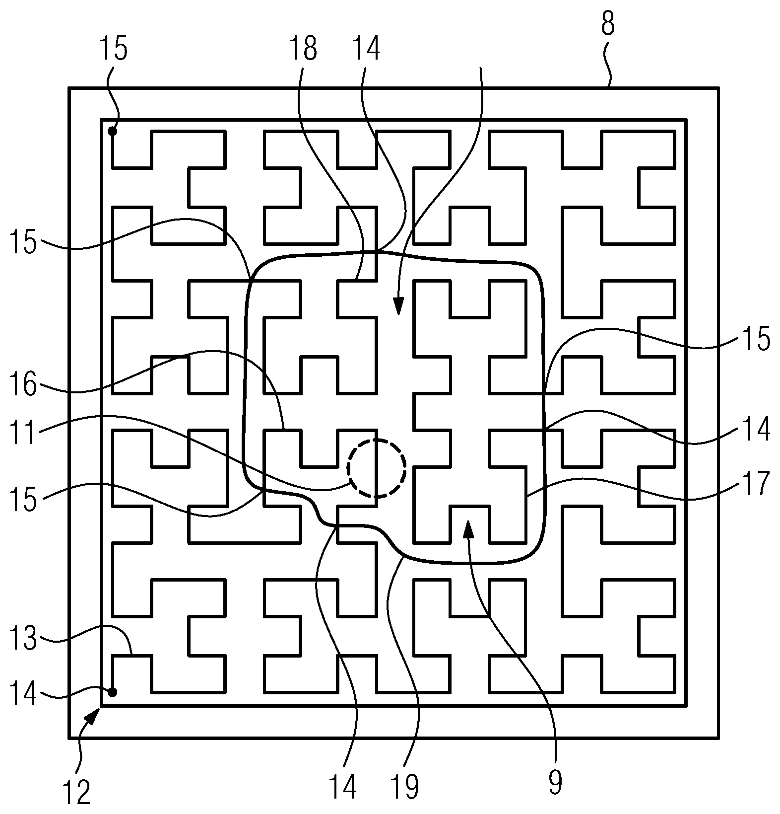
[0031] FIG. 2 shows a schematic view on the build plane 8 of the apparatus 1 from FIG. 1. In FIG. 2 the contour of the object 2, in particular the uppermost layer of the object 2, i.e. defining the region 9 that is to be irradiated, is depicted. Hence, in the actual layer the region 9 is to be irradiated via the energy beam 4, as described before. Hence, for generating the irradiation data, a track area 12 is defined, in this exemplary embodiment a square. Of course, it is also possible to define the track area in the whole build plane 8.
[0032] In the track area 12 a track segment 13 is generated between a starting point 14 and an end point 15, wherein the definition of the start point 14 and the end point 15 is arbitrary. The track segment 13 is based on a space-filling curve, for example a Hilbert curve. The space-filling curve thereby, fills the whole track area 12, wherein the energy beam 4 guided along the segmented track 13 would scan over the entire track area 12. In this exemplary embodiment, the space-filling curve is self-avoiding, i.e. does not intersect with itself.
[0033] Subsequently, the intersection can be generated between the region 9, as depicted via a contour 11 and the track area 12 in that three track segments 16, 17, 18 are generated in the region 9. At the intersection between the segmented track 13 in the track area 12 and the contour 11 of the object 2, in particular the region 9, a start point 14 and an end point 15 can be defined for each track segment 16, 17 and 18. Subsequently, the track segments 16, 17, 18 may be irradiated via the energy beam 4 in the sequence the track segments 16, 17 and 18 are defined in the track segment 13. In other words, the irradiation can start at the start point 14 of the track segments 16 and end at the end point 15 of the track segments 16. The end point 15 of the track segments 16 may be connected with the start point 14 of the track segments 17 in that the energy beam 4 can "jump" from the end point 15 of the track segments 16 to the start point 14 of the track segments 17.
[0034] Accordingly after the energy beam 4 is guided along the track segment 17 to the end point 15 of the track segment 17, the energy beam 4 can "jump" to the start point 14 of the track segment 18 and can be guided along the track segment 18 to the end point 15 of the track segment 18. Thus, the whole region 9 can be scanned via the energy beam 4 without introducing or with reduced mechanical stress in the layer of the object 2. In this exemplary embodiment, the track segment 13 is defined with respect to at least one parameter of the energy beam 4, for example a spot size of a spot 19 of the energy beam 4, as depicted via a dotted circle. In other words, the spot 19 of the energy beam 4 is guided along the track segments 16, 17 and 18, as described before, to irradiate the region 9 in the build plane 8.
[0035] The generation of irradiation data can of course be performed in advance to an additive manufacturing process or during an additive manufacturing process, for example in advance to the irradiation of each region 9 for every layer of the object 2. As can further be derived from FIG. 2, the region 11 is a comparatively massive structure without any filigree parts and can be understood as "core region", as no thin wall structures are comprised in the region 11. Of course, any arbitrary other space-filling curve can be used as basis for the generation of the segmented track 13, such as Peano-curves, E-curves, Z-curves, H-trees and the like.
[0036] Self-evidently, the inventive method for operating the apparatus may be performed on the apparatus 1, as described before. Further, the inventive method for generating the irradiation data may be performed on the control unit 10 that is comprised in the apparatus 1 (optional) in this exemplary embodiment. It is also possible that the control unit 10 receives the irradiation data are generated in another control unit external to the apparatus 1.
* * * * *
D00000
D00001
D00002
XML
uspto.report is an independent third-party trademark research tool that is not affiliated, endorsed, or sponsored by the United States Patent and Trademark Office (USPTO) or any other governmental organization. The information provided by uspto.report is based on publicly available data at the time of writing and is intended for informational purposes only.
While we strive to provide accurate and up-to-date information, we do not guarantee the accuracy, completeness, reliability, or suitability of the information displayed on this site. The use of this site is at your own risk. Any reliance you place on such information is therefore strictly at your own risk.
All official trademark data, including owner information, should be verified by visiting the official USPTO website at www.uspto.gov. This site is not intended to replace professional legal advice and should not be used as a substitute for consulting with a legal professional who is knowledgeable about trademark law.