Composite Part With External Part Cast Around Internal Insert And Method For Producing The Same
Reikher; Alexandre ; et al.
U.S. patent application number 16/344845 was filed with the patent office on 2020-02-13 for composite part with external part cast around internal insert and method for producing the same. The applicant listed for this patent is Shiloh Industries, Inc.. Invention is credited to Sam A. Kassoumeh, Alexandre Reikher.
| Application Number | 20200047243 16/344845 |
| Document ID | / |
| Family ID | 62076353 |
| Filed Date | 2020-02-13 |


| United States Patent Application | 20200047243 |
| Kind Code | A1 |
| Reikher; Alexandre ; et al. | February 13, 2020 |
COMPOSITE PART WITH EXTERNAL PART CAST AROUND INTERNAL INSERT AND METHOD FOR PRODUCING THE SAME
Abstract
Composite parts and methods for making the same are disclosed. A composite part may include an internal insert component that is coated on at least a portion of its surface with certain types of particles, an external part component cast around the coated insert, and a particle-rich region that is formed between the two components, where the particle-rich region includes particles from the coated insert. A method for producing a composite part may include the steps of: positioning an internal insert component that is coated on at least a portion of its surface within a mold cavity of a casting die; casting a molten material of the external part component around the coated insert; and solidifying the molten material to form the external part component of the composite part.
| Inventors: | Reikher; Alexandre; (Pleasanton, CA) ; Kassoumeh; Sam A.; (Canton, MI) | ||||||||||
| Applicant: |
|
||||||||||
|---|---|---|---|---|---|---|---|---|---|---|---|
| Family ID: | 62076353 | ||||||||||
| Appl. No.: | 16/344845 | ||||||||||
| Filed: | November 1, 2017 | ||||||||||
| PCT Filed: | November 1, 2017 | ||||||||||
| PCT NO: | PCT/US2017/059572 | ||||||||||
| 371 Date: | April 25, 2019 |
Related U.S. Patent Documents
| Application Number | Filing Date | Patent Number | ||
|---|---|---|---|---|
| 62415896 | Nov 1, 2016 | |||
| Current U.S. Class: | 1/1 |
| Current CPC Class: | B29C 2945/76083 20130101; B29C 2945/76294 20130101; B22D 19/08 20130101; B22D 19/14 20130101; B22D 19/00 20130101; B22D 17/24 20130101; B29C 45/14073 20130101 |
| International Class: | B22D 17/24 20060101 B22D017/24; B22D 19/08 20060101 B22D019/08 |
Claims
1. A composite metal part, comprising: an internal insert component that is made from a first metal material and includes a coating on at least a portion of an outer surface; an external part component that is made from a second metal material and is cast around at least a portion of the internal insert component; and a particle-rich region that includes a plurality of dispersed particles from the coating and is located between the internal insert component and the external part component, wherein the first metal material is different than the second metal material.
2. The composite metal part of claim 1, wherein the particle-rich region includes an intermetallic layer formed from the first metal material, the second metal material, and the coating.
3. The composite metal part of claim 1, wherein the particle-rich region forms a layer between the first and second metal materials having a thickness of approximately 20 micrometers (.mu.m) to 180 micrometers (.mu.m), inclusive.
4. The composite metal part of claim 1, wherein the first metal material includes a magnesium-based material.
5. The composite metal part of claim 1, wherein the internal insert component is hollow.
6. The composite metal part of claim 1, wherein the second metal material includes an aluminum-based material.
7. The composite metal part of claim 6, wherein the aluminum-based material includes one of an aluminum A380 alloy, an A360 alloy, an Aural-2 alloy, or an ADC12 alloy.
8. The composite metal part of claim 6, wherein both the coating on the internal insert component and the plurality of dispersed particles in the particle-rich region include at least one material selected from the group consisting of: a silicon-based material, a titanium-based material, an oxide, or a carbide.
9. The composite metal part of claim 1, wherein the composite metal part is a steering knuckle.
10. The composite metal part of claim 1, further comprising a support pin engaged with the internal insert component and cast with the external part component.
11. The composite metal part of claim 1, wherein the external part component defines a gap along an outer surface, thereby partially exposing the internal insert component.
12. The composite metal part of claim 1, wherein the particles of the coating of the internal insert component are initially applied in a substantially homogeneous distribution about the portion of the outer surface of the internal insert component.
13. A method of forming a composite part having an internal insert component and an external part component, comprising the steps of: positioning the internal insert component within a mold cavity, wherein the internal insert component comprises a first metal material, and wherein at least a portion of an outer surface of the internal insert component is covered with a coating comprising a plurality of particles; casting a molten material around the internal insert component, the molten material comprising a second metal material different from the first metal material; and solidifying the molten material to form the external part component of the composite part, thereby dispersing the particles to form a particle-rich region located between the internal insert component and the external part component.
14. The method of claim 13, further comprising cooling the internal insert component as the molten material is cast around the internal insert.
15. The method of claim 13, wherein the first metal material includes a magnesium-based material, and the second metal material includes an aluminum-based material.
16. The method of claim 15, wherein both the coating on the internal insert component and the plurality of dispersed particles in the particle-rich region include at least one material selected from the group consisting of: a silicon-based material, a titanium-based material, an oxide, or a carbide.
17. The method of claim 13, wherein the coating is distributed substantially homogeneously about the portion of the outer surface of the internal insert component.
18. The method of claim 17, wherein a percentage by weight of the coating varies no more than 12% along the portion of the outer surface of the internal insert component prior to the casting of the molten material.
19. The method of claim 13, further comprising cooling the particle-rich region using a directed cooling path to the internal insert component.
20. The method of claim 19, wherein the cooling path is along a support pin supporting the internal insert component in the mold cavity.
Description
CROSS-REFERENCE TO RELATED APPLICATIONS
[0001] This application claims priority to U.S. Provisional Patent Application Ser. No. 62/415,896, filed on Nov. 1, 2016, the contents of which are hereby expressly incorporated by reference in their entirety.
FIELD
[0002] The present disclosure relates to composite parts and, more particularly, to composite parts having a lightweight internal insert component and a die cast external part component.
BACKGROUND
[0003] Composite parts employing different materials may advantageously provide a blend of material properties. For example, a first material may provide relative strength or durability, while a second material different from the first may provide light weight or other desirable characteristics.
[0004] Composite parts are often difficult to assemble or form due to differing material properties of the multiple materials used. Merely as one example, one material may have a different coefficient of thermal expansion than another, and as a result the two materials may respond differently during any hot forming technique (e.g., casting) or cooldown from the same. More specifically, the different rates of thermal expansion may result in cracks, dislocations, gaps, or the like between the different materials. As a result, a bond between the different materials may be weakened or otherwise negatively affected.
[0005] Accordingly, there is a need for a composite part that addresses the above shortcomings.
DRAWINGS
[0006] FIG. 1 is a perspective view of an example of a composite part having an internal insert component and an external part component;
[0007] FIG. 2 is a front view of an example of a high pressure die casting fixture;
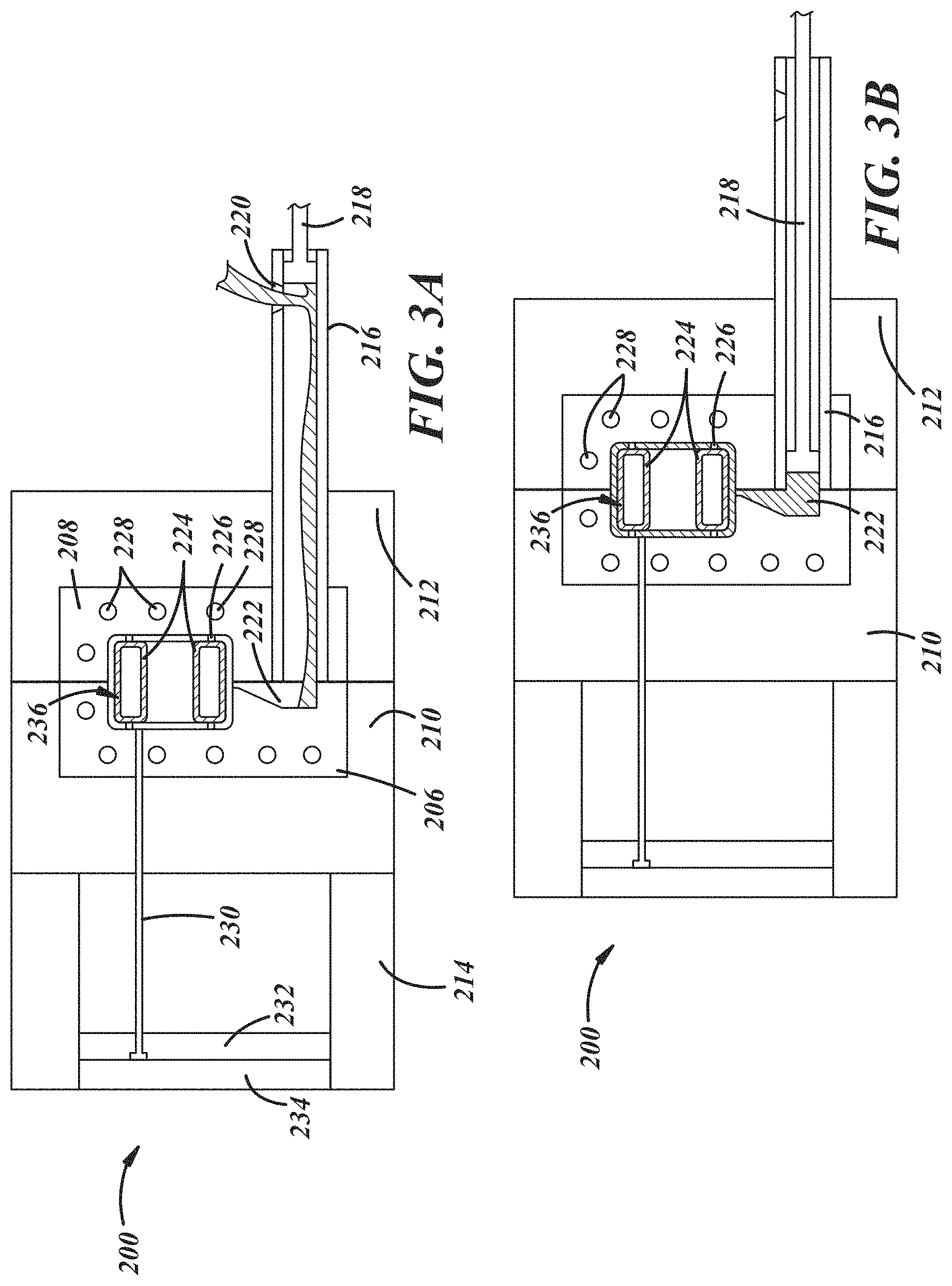
[0008] FIG. 3A is a front view of the casting die of FIG. 2, illustrating molten metal material being placed into a shot sleeve of the fixture;
[0009] FIG. 3B is a front view of the casting die of FIG. 2, illustrating a plunger forcing the molten metal material through the shot sleeve;
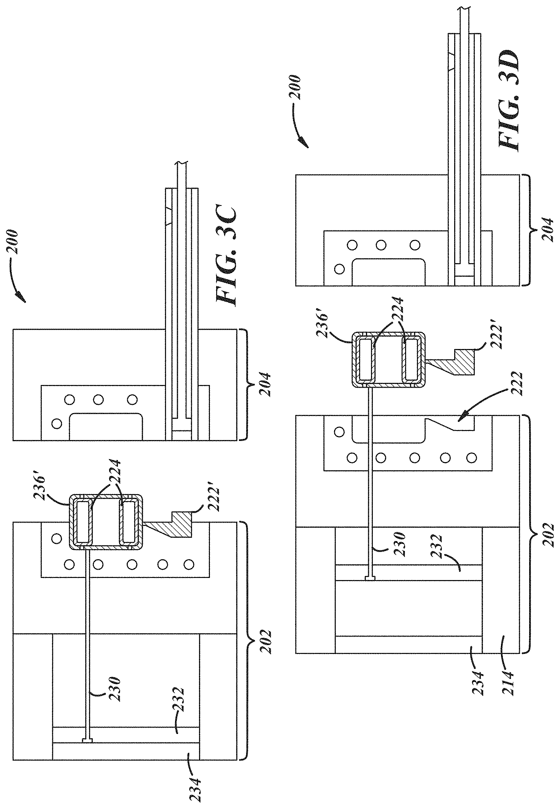
[0010] FIG. 3C is a front view of the casting die of FIG. 2, illustrating the die opening after a metallic part is solidified;
[0011] FIG. 3D is a front view of the casting die of FIG. 2, illustrating ejector pins forcing the metallic part out of the die;
[0012] FIG. 4A is a perspective view of a two-piece internal insert component that is placed within a casting die, such as that illustrated in FIG. 2, where molten metal material can flow and solidify around the insert so that the insert becomes integrated within the composite part, according to one example;
[0013] FIG. 4B is a perspective view of the internal insert component of FIG. 4A, shown assembled and partially sectioned;
[0014] FIG. 4C is a section view of the internal insert component of FIGS. 4A and 4B, shown installed in a casting die such as that illustrated in FIG. 2;
[0015] FIG. 5A is a lateral view of the internal insert component of FIGS. 4A-4C, shown installed in a casting die that includes several different examples of insert supports for holding the insert in place within the casting die;
[0016] FIG. 5B is a lateral view of an insert support for holding an internal insert component in place within a casting die, according to one example;
[0017] FIG. 5C is a lateral view of an insert support for holding an internal insert component in place within a casting die that has a cooling channel provided within the die, according to one example;
[0018] FIG. 5D is a lateral view of an insert support for holding an internal insert component in place within a casting die that has a phase change material provided within a support pin, according to one example;
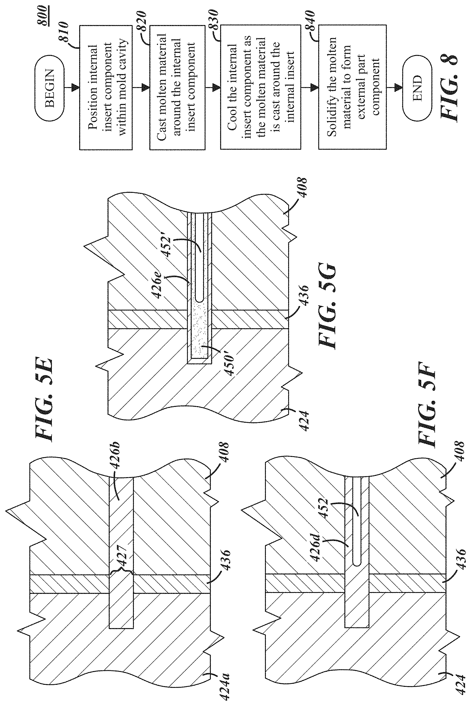
[0019] FIG. 5E is a lateral view of an insert support for holding an internal insert component in place within a casting die, where the support pin is permanently fixed to the die, according to one example;
[0020] FIG. 5F is a lateral view of an insert support for holding an internal insert component in place within a casting die, where the support pin is configured to provide liquid cooling, according to one example;
[0021] FIG. 5G is a lateral view of an insert support for holding an internal insert component in place within a casting die, where the support pin is permanently fixed within the die and is configured to provide active cooling by way of a phase change material, according to one example;
[0022] FIG. 5H is a longitudinal view of a composite part formed with an insert support used to support an internal insert component, where the insert support is permanently cast-in with the composite part;
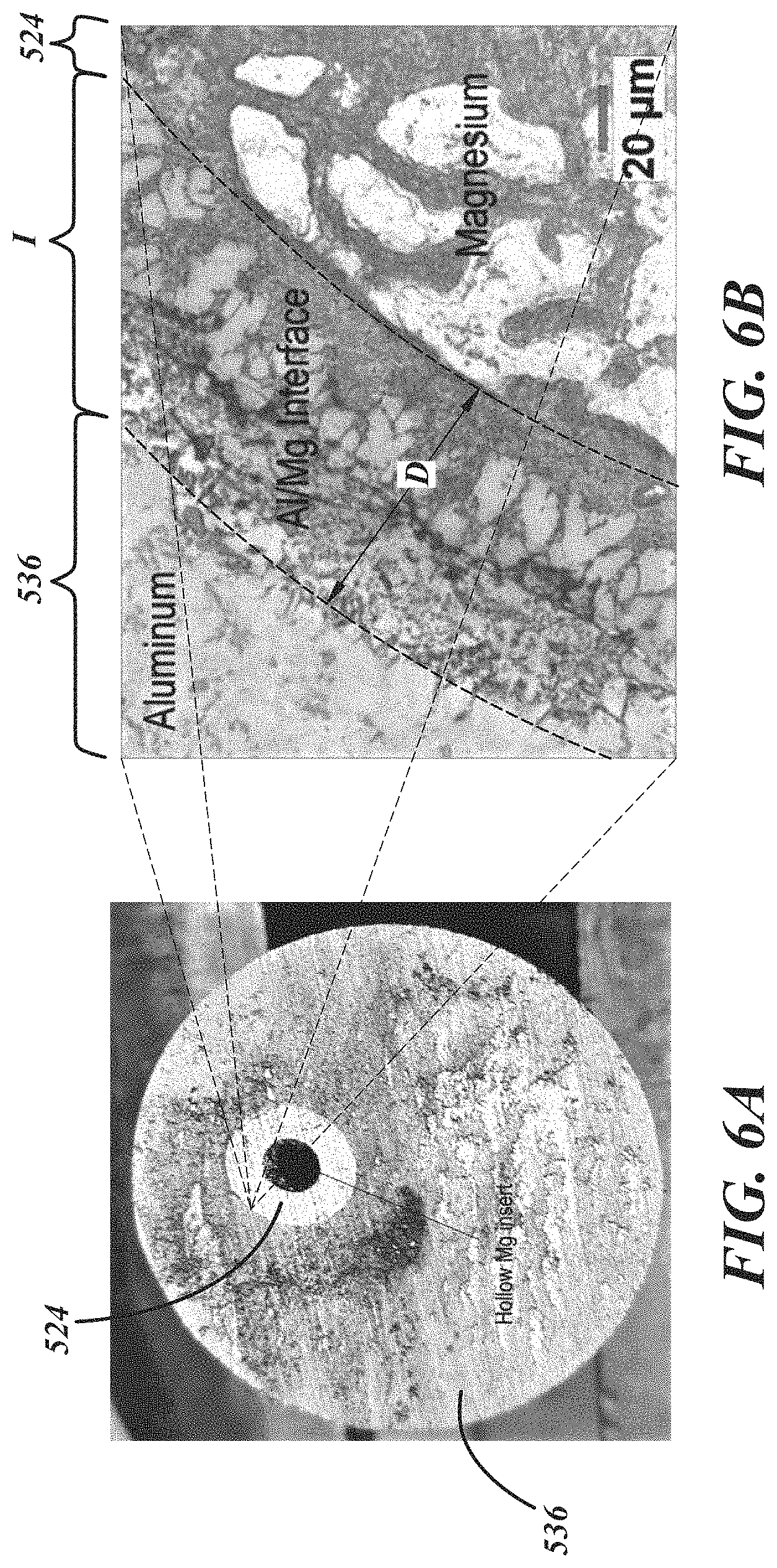
[0023] FIG. 6A is a sectional view of a finished composite part having an internal insert component and an external part component cast about the insert, according to one example;
[0024] FIG. 6B is another sectional view of a finished composite part having an internal insert component and an external part component, which is enlarged to show an interface region between the insert and part components;
[0025] FIG. 7A is a perspective view of an internal insert component for use in forming a composite part, according to one example;
[0026] FIG. 7B is a perspective view of the internal insert component shown in FIG. 7B, with a cap attached to an end of the insert;
[0027] FIG. 7C is a cutaway view of a composite part formed with the internal insert component shown in FIGS. 7A and 7B, according to one example;
[0028] FIG. 7D is another cutaway view of the composite part of FIG. 7C, according to one example; and
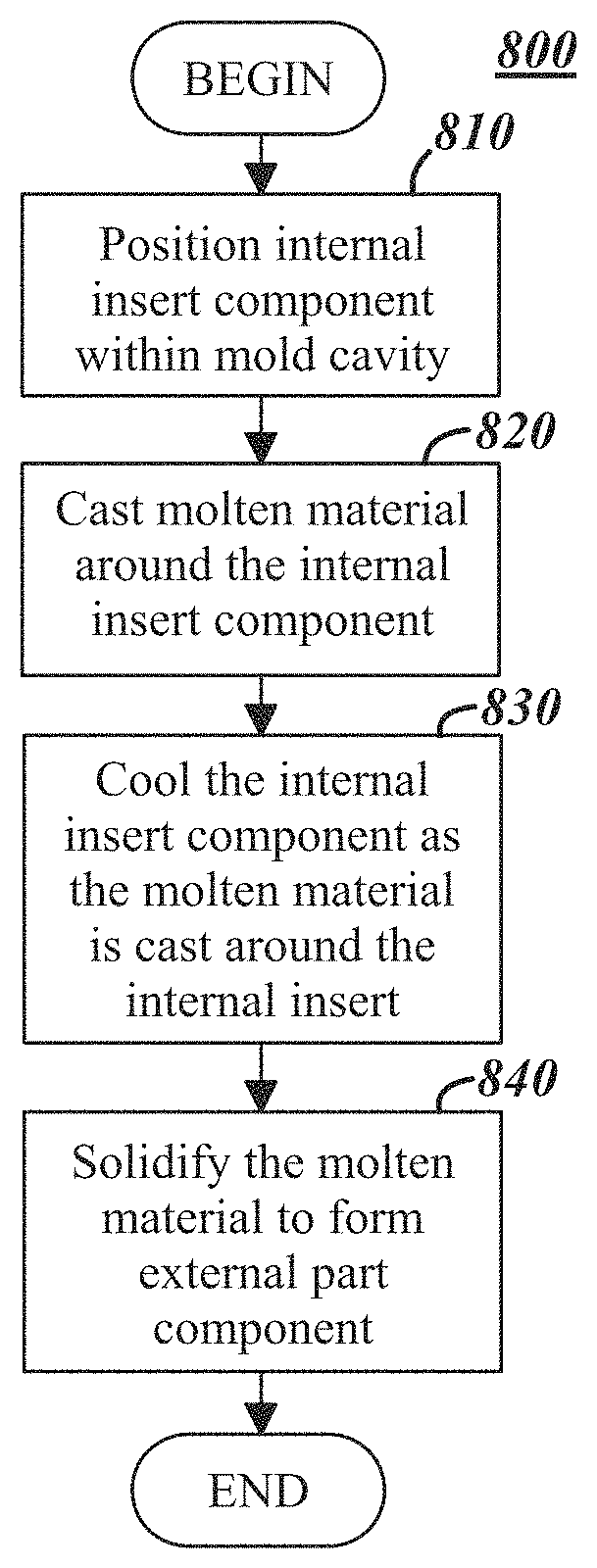
[0029] FIG. 8 is a process flow diagram for a method of forming a composite part where an external part component is cast and solidifies around an internal insert component during a die casting process, according to one example.
DESCRIPTION
[0030] Exemplary illustrations are provided herein of a composite part having an internal insert component and an external part component where the external part is cast and solidifies around the internal insert during a die casting operation, as well as methods and equipment for forming the same. The composite part is suitable for any number of applications, particularly those that seek to reduce the weight of the part, yet retain much of its strength. The terms "internal insert component," "internal insert," "insert component," "coated insert" and "insert" are used interchangeably in the present application, as are the terms "external part component," "external part," "part component," "cast part," "metallic part," etc.
[0031] According to a non-limiting example, a composite part includes an internal insert component that is made of a magnesium-based material and is coated on at least a portion of its surface with certain types of particles, an external part component that is made of an aluminum-based material or zinc-based material and is cast around the coated insert, and a particle-rich region that is formed between the two components, where the particle-rich region includes particles from the coated insert. The particle-rich region may generally improve material properties of the outer material, e.g., the aluminum or zinc material, for example by creating a more refined microstructure, and in some cases may improve bonding between the two components, e.g., by addressing differences in their coefficients of thermal expansion (COE). For instance, magnesium has a significantly higher COE than aluminum and, thus, experiences substantially more expansion and contraction in the presence and absence of heat. The particle-rich region is designed to reduce the undesirable effects of these differences, as well as that of oxide films on the surface of the internal insert component which can contribute to the formation of gaps between the two components. Macro, micro or even nano particles may be pre-applied to a surface of the internal insert component to help minimize such gaps and improve the bond between the components. In the example above, the composite part includes an internal insert component that is of a different material than the external part component; however, this is not required, as the insert and part components could both be formed from the same or similar materials, as well materials other than those listed herein.
[0032] According to another non-limiting example, a potential method for producing the composite part includes the steps of: positioning an internal insert component that is coated on at least a portion of its surface within a mold cavity of a casting die; casting a molten material of the external part component around the coated insert; cooling the coated insert as the molten material is cast around it; forming a particle-rich region between the coated insert and the part that is designed to offset differences in the coefficients of thermal expansion (COE) of the two components; solidifying the molten material to form the external part component of the composite part; and ejecting the composite part from the casting die.
[0033] As will be explained, one or more surfaces of the internal insert component may be coated with particles according to a number of techniques, including hot fusion, cold spraying, high velocity spraying, electrodeposition, or application of the particles as the insert is being formed (e.g., during a process of casting or otherwise forming the insert), to cite a few possibilities. Of course, any suitable technique for applying particles to an outside surface of the insert may be employed. Some examples of suitable particle materials include, but are not limited to: ceramic-based particles, graphite, diamond, magnesium-based particles such as MgO or MgAl.sub.2O.sub.4, aluminum oxide (Al.sub.2O.sub.3), silicon (Si) and oxides thereof such as silicon oxide (SiO.sub.2), SiC, titanium (Ti) and oxides thereof such as titanium oxide (TiO.sub.2), TiB.sub.2, Cr 526, nickel, copper, zinc and zinc oxide (ZnO.sub.2), silver and gold, to cite a few. In some examples particles may be relatively small, such as less than 1.0 millimeter in diameter or a maximum dimension thereof, and in some cases even smaller, e.g., less than 0.25 millimeters or less than 0.10 millimeters, merely as examples. Additionally, other oxides (e.g., yttrium oxide or Y.sub.2O.sub.3), nitrides, carbides, hydrides, and borides not specifically described above may be employed in addition to or in lieu of examples noted above. Carbon black, fullerenes and carbon nanotubes may also be used, as may intermetallic compounds such as NiAl and Al.sub.3Ti.
[0034] While any of the above particles may be employed in example illustrations, and although the particular particles used in a particular application may depend on the materials used in the internal insert component and/or the external part component, typically silicon-based and titanium-based particles may be particularly well-suited where aluminum-based alloy materials are employed in the external part component. Oxides (e.g., Al.sub.2O.sub.3) and carbides may also be well-suited for such applications.
[0035] It should be appreciated that the composite parts, methods and equipment described herein may be used in a wide variety of applications and industries. One particularly suitable application for such composite parts is the automotive industry, where lightweight parts such as steering knuckles, structural members, cross members, control arms, etc. are desired.
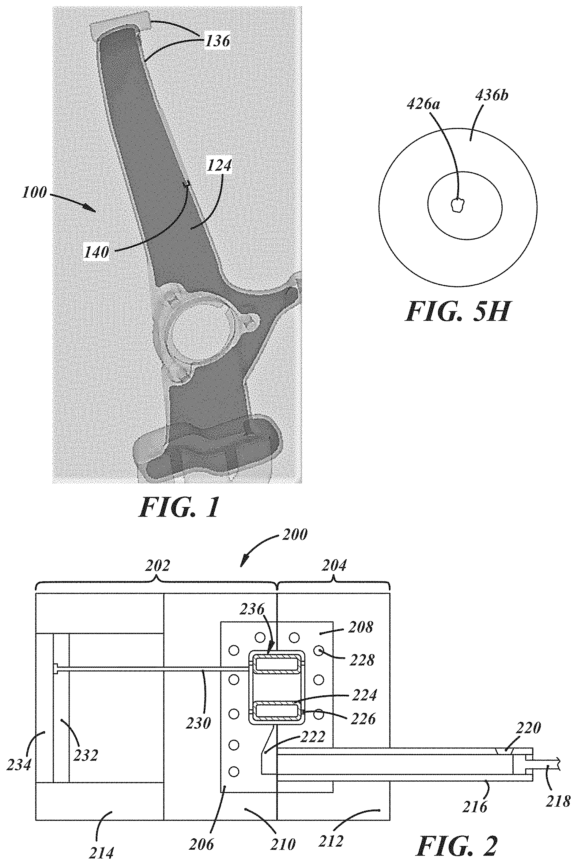
[0036] Merely by way of example, with reference to FIG. 1, there is shown a non-limiting example of a composite part in the form of a steering knuckle 100. The steering knuckle 100 may include an internal insert component 124, with an external part component 136 molded about the internal insert component 124.
[0037] The internal insert component 124 and external part component 136 may be formed from similar or different materials. For example, the external part component 136 may be formed from an aluminum-based material (for example, an aluminum alloy, such as aluminum A380 alloy, A360 alloy, Aural-2 alloy, or ADC12 alloy, merely as examples) and have a wall thickness of 6 mm or greater, while the internal insert component 124 may be formed from a magnesium-based material. In a different example, both the internal insert component 124 and the external part component 136 are made from aluminum-based materials, perhaps the same aluminum alloy or different aluminum alloys. Combinations of different materials in a single part 100 in this manner may facilitate part characteristics more ideally matched to a given application. For example, the steering knuckle 100 is relatively lightweight owing to the use of aluminum-based material in the external part component 136, but also has increased strength compared with uniformly aluminum-based parts owing to the use of magnesium-based materials for the internal insert 124. Moreover, a bond strength between the internal insert 124 and external part component 136 may be increased with the use of a particle-rich region 140 formed from a coating provided on at least a portion of the internal insert component 124 during the forming process of the steering knuckle 100. Other materials combinations may be employed. Moreover, in some applications it may be beneficial to form both the internal insert component 124 and external part component 136 from similar or even identical materials.
[0038] The particle-rich region 140 of the composite part 100 may be formed in any number of suitable ways. In some examples, particles are provided by applying a coating comprising the particles to at least a portion of an internal insert component prior to casting the external part component about the internal insert component. Upon injection of molten material into the mold, the molten material heats the internal insert component, and may melt at least an outer layer of the internal insert component. This outer layer of the internal insert component may generally mix with the molten material, and the particles may disperse to a limited extent within a particle-rich region or boundary area located between the internal insert component and the molten material. The molten material and any melted portion(s) of the internal insert component may subsequently be cooled, thereby forming an intermetallic layer where the position of the particles that have been dispersed is generally fixed, creating a particle-rich region between the internal insert component and the external part component.
[0039] Of course, the methods, equipment and composite parts described herein are not limited to such applications, as they are merely provided as examples. In view of the wide range of applications to which exemplary parts and methods may be directed, the description that follows is directed to relatively simplified part shapes to facilitate explanation of the exemplary concepts.
Tooling System
[0040] As noted above, the composite parts described herein may be formed in a casting process, where an external part component is generally cast around an internal insert component. Referring now to FIGS. 2 and 3A-3D, one example of a tooling system is illustrated, which may be used for forming a composite part and/or using any example methods described herein.
[0041] The tooling system 200 may include a mold for casting parts, e.g., in a high pressure die cast process. The tooling 200 comprises a moveable/ejector half 202 and a stationary half 204. The stationary half 204 may remain fixed, e.g., with respect to a support surface (not shown in FIG. 2), while the ejector half 202 may move, for example to facilitate removal of parts formed within the tooling 200, service/repair of the tooling 200, etc.
[0042] The ejector half 202 and stationary half 204 have an ejector half cavity block 206 and stationary half cavity block 208, respectively, which cooperate to define a mold for forming one or more composite parts. The ejector half cavity block 206 and stationary half cavity block 208 are supported by an ejector holder block 210 and a stationary holder block 212, respectively.
[0043] Molten material (not shown in FIG. 2) may be injected into a mold cavity 236 defined by the ejector half cavity block 206 and stationary half cavity block 208 by way of a sleeve 216. For example, molten material may be poured into a pour hole 220, and forced into the mold cavity 236 by a plunger 218, as will be described further below. The molten material may then enter the mold cavity 236 by way of a runner 222, which extends from an end of the sleeve 216 to the mold cavity 236.
[0044] As will be described further below, an internal insert component 224 may be positioned within the mold cavity 236 so that molten material can be cast around it. For example, one or more locating pins 226 may be used to position and maintain the internal insert component 224 within the mold cavity 236. Upon being positioned within the mold cavity 236, molten material may be cast about the internal insert component 224.
[0045] One or more cooling channels 228 may be provided adjacent the mold cavity to facilitate management of a mold temperature and/or cooling of molten material within the mold cavity 236. Moreover, as will be described further below, in some examples cooling passages or other features may be incorporated into or located adjacent the locating pins 226. The locating pins 226 may thereby facilitate cooling of the internal insert component 224 at any point during the casting process. Cooling directed at the internal insert component 224 in this manner may also facilitate formation of a particle-rich region in the resulting composite part, as will be discussed further below.
[0046] One or more ejector pin(s) 230 may be provided to facilitate removal of a formed composite part from the mold cavity 236. Although a single ejector pin 230 is illustrated in FIG. 2, any number of additional ejector pins 230 may be provided that is convenient. Ejector pin(s) 230 may be fixed at an end away from the mold cavity 236 to a movable ejector plate 232, which slides along a stationary support block 214. An ejector pin support plate 234 may also be provided, which may be fixed to the support block 214. The support plate 234 may facilitate movement of the slidable ejector plate 232 by providing a stationary reaction surface for the ejector plate 232.
[0047] Referring now to FIGS. 3A-3D, the operation of the tooling system 200 will be described in further detail. As shown in FIG. 3A, the internal insert component 224 may initially be positioned within the mold cavity 236. The internal insert component 224, as will be described further below, may have at least a portion of an outer surface thereof coated with particles that are configured to enhance bonding of the internal insert component 224 with a molten material subsequently injected into the mold cavity 236 and into contact with the outer surface of the internal insert component 224.
[0048] The internal insert component 224 may be located within the mold cavity 236 using one or more locating pins 226, and a molten material may be poured into sleeve 216 through the pour hole 220. Any molten material may be employed that is convenient. Merely by way of example, a magnesium-based material coated with ceramic particles may be used for the internal insert component 224, and an aluminum-based material such as an aluminum alloy may be used for the molten material of the external part component.
[0049] Turning to FIG. 3B, the plunger 218 may be urged through the sleeve 216, thereby forcing the molten material out of the sleeve 216, through the runner 222, and into the mold cavity 236. In one example approach, the plunger 218 injects the molten material into the mold cavity 236 in a two-stage process where the plunger 218 initially moves in a first stage at a relatively slow first speed as the molten material is moved through the sleeve 216 and into the runner 222. In a second stage, the plunger 218 injects the molten material into the mold cavity 236 at increased pressure, which may be imparted to the molten material by an increase in speed and/or force of the plunger 218 as it moves through the sleeve 218.
[0050] Upon injection of the molten material into the mold cavity 236, the molten material may be cooled, e.g., by way of cooling channels 228. Additionally, the locating pins 226 may be disposed adjacent to one or more of the cooling channels 228, or be provided with features internal to the locating pin(s) 226 that facilitate cooling within the mold cavity 236. Moreover, cooling features of the locating pins 226 may facilitate cooling that is focused on the internal insert component 224, thereby allowing enhanced cooling of the composite part from the inside as it is formed. As will be described further below, enhanced cooling (particularly adjacent a particle-rich region or interface between an internal insert component and external part component) may allow not only faster cycle times due to overall faster cooling, but also enhanced material properties resulting from reductions in average grain size of the formed part. Enhanced cooling may provide a directed cooling path to the internal insert component 224 or regions thereof, e.g., by way of locating pin(s) such as locating pin 226 or other examples provided below.
[0051] Referring now to FIG. 3C, upon solidification of the molten material, the composite part 236' has been substantially formed from the internal insert component 224 and the solidified molten material surrounding at least a portion of the internal insert component 224. Additionally, a flashing 222' may have been formed during the solidification process, resulting from molten material which solidified within the runner 222. Once the molten material is solidified within the mold cavity 236, the movable ejector half 202 of the tool 200 may be moved away from the stationary half 204, exposing the solidified part 236'. The ejector pin(s) 130 may urge the solidified part out of the ejector half 202 of the tool, as seen in FIG. 3D. For example, the ejector plate 232 may slide laterally with respect to the support plate 214, thereby moving the ejected pin(s) 230 and forcing the composite part 236' out of the tool 200. The flashing 222' may be subsequently removed from the composite part 236' and recycled. Moreover, any additional finishing steps, e.g., machining, grinding, polishing, may be performed on the composite part 236' to remove additional flashing (not shown in FIG. 3D) or other portions of the composite part 236' that may be undesirable.
[0052] Turning now to FIGS. 4A-4C, an exemplary internal insert component comprising separate halves 324a, 324b (collectively, internal insert component 324) is illustrated. The two halves 324a, 324b may be assembled together and placed within a mold cavity for forming a composite part 236' as described above. The internal insert 324 may also have at least a portion of an outer surface thereof coated with certain types of particles 340. As will be described further below, the particles 340 may enhance bonding of the internal insert component 324 and the molten material used to form the external part component of the composite part. While the internal insert component 324 of FIGS. 4A-4C is illustrated as being generally hollow and rectangular, in other approaches a solid insert or inserts of other shapes may be employed. Hollow inserts will likely be favored in applications that are focused on reducing the weight of the composite part.
[0053] The two halves 324a, 324b may initially be assembled together, as best seen in the perspective sectional view of FIG. 4B. A coating of at least a portion of an outer surface of one or both halves 324a, 324b may occur prior to or after assembly of the two halves 324a, 324b. Once the internal insert component 324 is assembled and the particles 340 are applied thereto, the internal insert component 324 may be placed within a mold cavity defined by mold portions 306, 308 (see FIG. 4C). While the preceding description of the internal insert component 324 describes a two-piece insert, it is certainly possible for the insert to be a one-piece insert or to have more than two pieces.
[0054] In some examples, one or more locating pins may be used to position an internal insert component within a mold cavity. Example locating pins will now be described in further detail, referring to FIGS. 5A-5G.
[0055] As shown in FIGS. 5A and 5B, in one example approach, a locating pin 426a may be cast-in to the resulting composite part 436 so that it becomes part of the resulting composite part. The locating pin 426a may initially be cast into or pressed into an internal insert component 424 (comprising halves 424a, 424b, as shown in FIG. 5A, with the locating pin 426a being shown disposed in the half 424b in FIG. 5B). As molten material introduced into the mold cavity cools, solidifying the molten material and permanently bonding to the internal insert component 424, the cast-in locating pin 426a may also become permanently bonded with the solidified external part component 436. An example of a cast-in locating pin 426a is shown in section in FIG. 5B, where the cast-in locating pin has become part of the resulting composite part and may be made of an aluminum-based material suitable in composition to that of the molten material.
[0056] In another example illustrated in FIG. 5A, a locating pin 426b may be permanently installed in the mold. Accordingly, the locating pin 426b does not become part of the resulting composite part. An example of the permanent support pin 426b is shown in further detail in FIG. 5E. The support pin 426b is permanently joined or fixed within the die 408, and extends into the mold cavity to support the internal insert component 424a. Accordingly, molten material does not permanently join with the locating pin 426b, but rather forms the composite part by surrounding the internal insert component 424a without permanently bonding with the molten material forming the external part component 436.
[0057] As mentioned above, locating pin(s) used to position an internal insert component within a mold cavity may also facilitate cooling within the mold cavity. For example, locating pins may provide cooling of the molten material introduced to the cavity, the internal insert component, a boundary region between the molten material and the internal insert component, or any combination/sub-combination of the three. In this manner, bonding of the molten material introduced to the mold cavity around the internal insert component may be enhanced by allowing enhanced control of temperatures within the mold cavity, especially in a boundary region between the internal insert component and the molten material of the external part component. As noted above, enhanced cooling (such as by way of the various example approaches adjacent a particle-rich region or interface between an internal insert component and external part component described below) may allow faster cycle times due to overall faster cooling. Moreover, reductions in average grain size of the formed part may also be achieved by way of the faster cooling in the particle-rich and/or interface region. More specifically, in one example average grain size was reduced from an average of 78.times.52 microns in a traditional casting process to an average of 37.times.32 microns (by averaging measured boundaries of grains in a two-dimensional micrograph or photo) using the faster cooling methodologies where cooling is performed adjacent the particle-rich or interface region.
[0058] Turning now to FIG. 5C, one example of a locating pin providing cooling within the mold cavity is illustrated. A mold cavity defined in part by a mold 408 may have a locating pin 426b permanently installed within the mold, similar to the example discussed above in FIG. 5E. In the example shown in FIG. 5C, however, a cooling channel 428 passes through the mold 408 adjacent an end of the locating pin 424b. As such, the locating pin 424b is in contact with and removes heat from the internal insert component 424a and provides it to fluid flowing through the cooling channel via conduction cooling such that it cools the internal insert component 424a and/or external part component 436.
[0059] Referring now to FIG. 5D, another support pin with a cooling feature is illustrated. Locating pin 426c is hollow and defines an internal space that receives a phase change material (PCM) 450 that is configured to absorb heat by way of phase changes of the PCM 450. For example, heat may be absorbed through the locating pin 426c by way of the PCM 450 changing from a solid phase to a liquid phase. Heat may be stored in the PCM 450 and transferred to the mold 408, thereby conducting heat away from the molten material as it cools to form the external part component 436. Moreover, heat conduction may be enhanced by providing cooling channels in the mold 408, e.g., similar to cooling channel 428 described above in conjunction with FIG. 5C. Example phase change materials that may be used as PCM 450 may include, but are not limited to:
[0060] sodium sulfate (Na.sub.2SO.sub.4*10H.sub.2O);
[0061] NaCl*Na.sub.2SO.sub.4*10H.sub.2O; or
[0062] Na.sub.2SiO.sub.3*5H.sub.2O.
[0063] Turning now to FIG. 5F, another example locating pin 426d is shown. Locating pin 426d may have a liquid cooling passage 452 defined therein to provide enhanced cooling of a mold cavity. Liquid cooling passage 452 may receive coolant from or otherwise be in fluid communication with other cooling passages of the mold 408, e.g., cooling passage 428 described above. Alternatively, the liquid cooling passage 452 may be a generally separate cooling circuit from other cooling passages of the mold 408. Support pin 426d conducts heat away from the internal insert component 424 via the coolant flow through the liquid cooling passage 452.
[0064] Referring now to FIG. 5G, another locating pin 426e is illustrated. Locating pin 426e includes both a phase change material (PCM) 450', as well as a liquid cooling passage 452'. By combining PCM 450' with a liquid cooling channel 452', cooling of the mold cavity may be further enhanced. It should be appreciated that in each of the embodiments shown in FIGS. 5C-D and 5F-G, the support pins both support the internal insert component, as well as help control the temperature of the internal insert component as the molten material of the external part component is cast and solidifies around it.
[0065] As noted above, locating pins may be used to support and/or provide targeting cooling with respect to an internal insert component. Referring now to FIG. 5H, in examples where locating pin 426a is cast-in to the composite part, the completed composite part may have the cast-in locating pin 426a protruding from the external part component 436, the completed composite part is illustrated with the locating pin 426a protruding from within the external part component 436 of the composite part. The locating pin 426a may be made of an aluminum-based material suitable in composition to that of the molten material that forms the external part component 436 about the internal insert component 424b (not shown in FIG. 5H).
[0066] By contrast, in examples where a locating pin 426b is permanently installed in the mold (e.g., as shown in FIG. 5E) and the locating pin 426b does not become part of the resulting composite part, the locating pin 426b may leave a gap or void in the external part component surrounding the internal insert component, exposing a portion of the internal insert component within. More specifically, in the example of FIG. 5E, the permanent support pin 426b extends into the mold cavity to support the internal insert component 424a. Molten material does not permanently join with the locating pin 426b, as noted above, but rather forms the composite part by surrounding the internal insert component 424a around the locating pin 426b. Upon removal of the part from the mold, a gap or void 427 is left in the external part component 436 surrounding the internal insert component 424a. As a result, the internal insert component 424a is partially exposed where the locating pin 426b had contacted the internal insert component 424a to support the internal insert component 424a within the mold.
Composite Part
[0067] Turning now to FIGS. 6A and 6B, an example composite part is illustrated. The composite part is shown in a cutaway view to illustrate an internal insert component 524 that defines a generally cylindrical shape, and is surrounded by an external part component 536. Particles applied to a surface of the internal insert component 524 may generally disperse throughout a boundary region located between the external part component 536 and the internal insert component 524. In this manner, a particle-rich region I may be formed that at least partially surrounds the internal insert component 524. According to the embodiment where the internal insert component 524 is made of a magnesium-based material and is coated with ceramic particles and the exterior part component 536 is made of an aluminum-based material, the particle-rich region I includes an aluminum/magnesium intermetallic interface with ceramic particles for enhanced bonding. More generally, an intermetallic interface may be formed from three materials: the material comprising the external part component (e.g., external part component 536), the internal insert component (e.g., internal insert component 524), and the particles. The particle-rich region I can certainly vary in terms of thickness and composition, but according to one example, it has a thickness of approximately 20 .mu.m-180 .mu.m, inclusive, and even more preferably a thickness of about 40 .mu.m-120 .mu.m, inclusive.
[0068] A concentration of the particles may form a gradient through the material, e.g., where they are more concentrated in a portion of the particle-rich region closest to the insert, and less concentrated in a portion of the particle-rich region that is closest to the external part. However, one potential advantage of using an internal insert component 524 that is pre-coated with particles is that, after solidification of the molten metal of the external part component 536, the particle-rich region I generally exhibits a more homogeneous distribution of particles which in turn can promote a more even distribution of nucleation sites, better micro-structure refinement, dislocation pinning, and increased bond strength in general.
[0069] In one example, the internal insert component 524 is initially coated with approximately 15% by weight particles on an outer surface of the internal insert component 524. With a substantially homogeneous distribution of the particles on the surface, a reduced grain size of the resulting particle-rich region I may be achieved. In one example, grain size in the particle-rich region may be reduced by 30% to 50% in an example where the particles have a substantially homogeneous distribution on the portion(s) of the outer surface of the internal insert component 524 that is coated, as compared with comparable materials or alloys having poor particle-dispersion homogeneity or formed without particles. In some previous methods of introducing particles in casting, clustering of the particles together has resulted, which may defeat the purpose of using the particles as it produces regions with non-uniform microstructure (and, as a result, deteriorated mechanical and bonding properties). In one example of a substantially homogeneous distribution of particles, a measurement by weight percentage of the particle distribution does not vary more than_12% anywhere on the portion(s) of the outer surface of the internal insert component 524 that is coated with particles. For example, in an embodiment where particles have a 15% by weight distribution on the surface of the internal insert component 524 as noted above, a substantially homogeneous distribution means that a percentage by weight of the particles in the portion(s) of the outer surface of the internal insert component 524 that are coated may vary from 13.2% by weight to 16.8% by weight.
[0070] Referring now to FIGS. 7A-7D, another example of internal insert component 624 and external part component 636 is illustrated. The internal insert component 624 may be hollow and formed of magnesium (although other materials could be used instead), and comprises a main body portion 624a and cap portion 624b. The main body portion 624a and cap portion 624b may be assembled together to form the internal insert component 624. Portions of one or both of the cap portion 624b and main body portion 624a may be coated with particles such as any of the examples described above. The assembled internal insert component 624 may then be placed into a mold (not shown in FIGS. 7A-7D), and an external part component 636 may be formed about the internal insert component 624 by injecting molten aluminum material into the mold cavity, e.g., by a high-pressure die cast process. Accordingly, a particle-rich region may be provided between the internal insert component 624 and external part component 636.
Method of Producing Composite Part
[0071] Turning now to FIG. 8, an example process 800 is illustrated for forming a composite part having an internal insert component and an external part component. Process 800 may begin at block 810, where an internal insert component is positioned in a mold cavity. For example, as described above an internal insert component 224, 324, 424, 524, or 624 may be positioned within a mold. In some examples, the internal insert component may be provided with a coating on at least a portion of an outer surface, in order to facilitate the formation of a particle-rich region. While the internal insert component may be formed of any material that is convenient, example materials include magnesium-based alloys and other materials. Process 800 may then proceed to block 820.
[0072] At block 820, a molten material may be cast about the internal insert component. For example, as described above a molten aluminum-based material may be introduced to a mold cavity containing the internal insert component. Any number of different casting processes may be used including, but not limited to, gravity casting, low pressure casting and high pressure die casting. According to some embodiments, high pressure die casting of aluminum alloys is preferred.
[0073] Proceeding to block 830, the internal insert component may be cooled as the molten material is cast about the internal insert component. Cooling may be facilitated, for example, using locating or support pin(s) 226, 326, 426 as described above. Consistent with the examples provided, cooling using the locating pin(s) 226, 326, 426 may be facilitated with a phase-change material, by way of a solid locating pin conducting heat from the mold, and/or with liquid cooling channels within the locating pin, merely as examples. Process 800 may then proceed to block 840.
[0074] At block 840, the molten material may be solidified to form an external part component disposed about the internal insert component. Molten material may be cooled or solidified using cooling features in the mold or locating pin(s). Moreover, as described above, in some approaches a particle-rich region may be formed between the internal insert component and external part component, e.g., by dispersion of particles applied in initially in a coating to a portion of the internal insert component, as described above.
[0075] It is to be understood that the foregoing description is not a definition of the invention, but is a description of one or more exemplary illustrations of the invention. The invention is not limited to the particular example(s) disclosed herein, but rather is defined solely by the claims below. Furthermore, the statements contained in the foregoing description relate to particular exemplary illustrations and are not to be construed as limitations on the scope of the invention or on the definition of terms used in the claims, except where a term or phrase is expressly defined above. Various other examples and various changes and modifications to the disclosed embodiment(s) will become apparent to those skilled in the art. All such other embodiments, changes, and modifications are intended to come within the scope of the appended claims.
[0076] As used in this specification and claims, the terms "for example," "e.g.," "for instance," "such as," and "like," and the verbs "comprising," "having," "including," and their other verb forms, when used in conjunction with a listing of one or more components or other items, are each to be construed as open-ended, meaning that that the listing is not to be considered as excluding other, additional components or items. Other terms are to be construed using their broadest reasonable meaning unless they are used in a context that requires a different interpretation.
* * * * *
D00000
D00001
D00002
D00003
D00004
D00005
D00006
D00007
D00008
XML
uspto.report is an independent third-party trademark research tool that is not affiliated, endorsed, or sponsored by the United States Patent and Trademark Office (USPTO) or any other governmental organization. The information provided by uspto.report is based on publicly available data at the time of writing and is intended for informational purposes only.
While we strive to provide accurate and up-to-date information, we do not guarantee the accuracy, completeness, reliability, or suitability of the information displayed on this site. The use of this site is at your own risk. Any reliance you place on such information is therefore strictly at your own risk.
All official trademark data, including owner information, should be verified by visiting the official USPTO website at www.uspto.gov. This site is not intended to replace professional legal advice and should not be used as a substitute for consulting with a legal professional who is knowledgeable about trademark law.