Prosthetic Valve With Separably-deployable Valve Body And Tissue Anchors
HARITON; Ilia ; et al.
U.S. patent application number 16/660231 was filed with the patent office on 2020-02-13 for prosthetic valve with separably-deployable valve body and tissue anchors. This patent application is currently assigned to CARDIOVALVE LTD.. The applicant listed for this patent is CARDIOVALVE LTD.. Invention is credited to Boaz HARARI, Ilia HARITON.
| Application Number | 20200046497 16/660231 |
| Document ID | / |
| Family ID | 55443277 |
| Filed Date | 2020-02-13 |
View All Diagrams
| United States Patent Application | 20200046497 |
| Kind Code | A1 |
| HARITON; Ilia ; et al. | February 13, 2020 |
PROSTHETIC VALVE WITH SEPARABLY-DEPLOYABLE VALVE BODY AND TISSUE ANCHORS
Abstract
Prosthetic valves and methods of use of prosthetic valves may be provided. In one implementation, a method of implanting a prosthetic valve within a native heart valve may be provided. The method may include delivering the prosthetic valve into a heart chamber while the prosthetic valve is constrained in a radially-contracted delivery configuration. The method may also include unconstraining ventricular tissue anchors and atrial tissue anchors of the prosthetic valve while maintaining an annular valve body of the prosthetic valve in the delivery configuration. The method may also include unconstraining the annular valve body from the delivery configuration while the unconstrained atrial tissue anchors and ventricular tissue anchors are positioned within an atrium and a ventricle, respectively. Unconstraining the annular valve body may decrease a longitudinal distance between the ventricular tissue anchors and atrial tissue anchors to secure the prosthetic valve within the native heart valve.
| Inventors: | HARITON; Ilia; (Zichron Yaackov, IL) ; HARARI; Boaz; (Ganey Tikva, IL) | ||||||||||
| Applicant: |
|
||||||||||
|---|---|---|---|---|---|---|---|---|---|---|---|
| Assignee: | CARDIOVALVE LTD. Or Yehuda IL |
||||||||||
| Family ID: | 55443277 | ||||||||||
| Appl. No.: | 16/660231 | ||||||||||
| Filed: | October 22, 2019 |
Related U.S. Patent Documents
| Application Number | Filing Date | Patent Number | ||
|---|---|---|---|---|
| 16042129 | Jul 23, 2018 | 10463488 | ||
| 16660231 | ||||
| 15682789 | Aug 22, 2017 | 10449047 | ||
| 16042129 | ||||
| 15541783 | Jul 6, 2017 | 9974651 | ||
| PCT/IL2016/050125 | Feb 3, 2016 | |||
| 15682789 | ||||
| 62112343 | Feb 5, 2015 | |||
| Current U.S. Class: | 1/1 |
| Current CPC Class: | A61F 2220/0016 20130101; A61F 2/243 20130101; A61F 2002/91575 20130101; A61F 2/2418 20130101; A61F 2/9517 20200501; A61F 2/2409 20130101; A61F 2220/0025 20130101; A61F 2/2436 20130101 |
| International Class: | A61F 2/24 20060101 A61F002/24 |
Claims
1-72. (canceled)
73. A method of implanting a prosthetic valve within a native heart valve, the method comprising: delivering the prosthetic valve into a heart chamber while the prosthetic valve is constrained in a radially-contracted delivery configuration, wherein the prosthetic valve comprises: an annular valve body, a plurality of ventricular tissue anchors configured to extend from the annular valve body, and a plurality of atrial tissue anchors configured to extend from the annular valve body; unconstraining the ventricular tissue anchors and the atrial tissue anchors within the heart while maintaining the annular valve body in the radially-contracted delivery configuration; and while the unconstrained ventricular tissue anchors are positioned downstream of the native heart valve and while the unconstrained atrial tissue anchors are positioned upstream of the native heart valve, unconstraining the annular valve body such that the annular valve body radially expands from the radially-contracted delivery configuration into a deployed configuration, wherein the radial expansion of the annular valve body decreases a longitudinal distance between the unconstrained ventricular tissue anchors and the unconstrained atrial tissue anchors to secure the prosthetic valve within the native heart valve.
74. The method of claim 73, wherein unconstraining the ventricular tissue anchors causes terminal ends of the ventricular tissue anchors to deflect radially outward relative to the annular valve body, and wherein unconstraining the atrial tissue anchors causes terminal ends of the atrial tissue anchors to deflect radially outward relative to the annular valve body.
75. The method of claim 73, further comprising: prior to unconstraining the atrial tissue anchors, moving the unconstrained ventricular tissue anchors so that the unconstrained ventricular tissue anchors engage tissue of the native heart valve.
76. The method of claim 73, wherein the prosthetic valve comprises: a first point of connection between the annular valve body and at least one ventricular tissue anchor; and a second point of connection between the annular valve body and at least one atrial tissue anchor, wherein the radial expansion of the annular valve body decreases a longitudinal distance between the first point of connection and the second point of connection.
77. The method of claim 76, wherein the radial expansion of the annular valve body shifts the first point of connection and the second point of connection radially outward.
78. The method of claim 73, wherein the prosthetic valve is configured to be symmetrical about a longitudinal axis extending through the center of the annular valve body.
79. The method of claim 73, wherein the annular valve body comprises: an outer frame from which the ventricular tissue anchors extend; and an inner frame from which the atrial tissue anchors extend, the inner frame being situated at least partially within the outer frame, wherein the outer frame and the inner frame are constrained in the radially-contracted delivery configuration during the unconstraining of the ventricular tissue anchors and during the unconstraining of the atrial tissue anchors.
80. The method of claim 79, wherein a longitudinal distance between an upstream end and a downstream end of the outer frame is decreased when the annular valve body is unconstrained, and wherein a longitudinal distance between an upstream end and a downstream end of the inner frame is decreased when the annular valve body is unconstrained.
81. The method of claim 79, wherein the outer frame and inner frame are configured to be symmetrical about a longitudinal axis extending through the center of the annular valve body.
82. The method of claim 73, wherein the ventricular tissue anchors are configured to be offset from the atrial tissue anchors, with respect to a circumference of the annular valve body.
83. A method of implanting a prosthetic valve within a native heart valve, the method comprising: delivering the prosthetic valve into a heart chamber while the prosthetic valve is constrained in a radially-contracted delivery configuration, wherein the prosthetic valve comprises: an annular valve body, a plurality of ventricular tissue anchors configured to extend from the annular valve body, wherein at least one ventricular tissue anchor has a single point of connection to the annular valve body, and a plurality of atrial tissue anchors configured to extend from the annular valve body, wherein at least one atrial tissue anchor has a single point of connection to the annular valve body; unconstraining the ventricular tissue anchors and the atrial tissue anchors within the heart while maintaining the annular valve body in the radially-contracted delivery configuration, wherein unconstraining the ventricular tissue anchors causes terminal ends of the ventricular tissue anchors to deflect radially outward relative to the annular valve body; and while the unconstrained ventricular tissue anchors are positioned downstream of the native heart valve and while the unconstrained atrial tissue anchors are positioned upstream of the native heart valve, unconstraining the annular valve body from the radially-contracted delivery configuration.
84. The method of claim 83, wherein each ventricular tissue anchor has a single point of connection to the annular valve body that is distinct from the points of connection between the other ventricular tissue anchors and the annular valve body, and wherein each atrial tissue anchor has a single point of connection to the annular valve body that is distinct from the points of connection between the other atrial tissue anchors and the annular valve body.
85. The method of claim 84, wherein beyond the points of connection between the ventricular tissue anchors and the annular valve body, the ventricular tissue anchors are devoid of interconnections, and wherein beyond the points of connection between the atrial tissue anchors and the annular valve body, the atrial tissue anchors are devoid of interconnections.
86. The method of claim 83, wherein unconstraining the atrial tissue anchors causes terminal ends of the atrial tissue anchors to deflect radially outward relative to the annular valve body.
87. The method of claim 83, wherein unconstraining the annular valve body causes the annular valve body to radially expand from the radially-contracted delivery configuration into a deployed configuration, and wherein the radial expansion of the annular valve body secures the prosthetic valve to the native heart valve.
88. The method of claim 83, wherein the prosthetic valve is configured to be symmetrical about a longitudinal axis extending through the center of the annular valve body.
89. The method of claim 83, wherein the annular valve body comprises: an outer frame from which the ventricular tissue anchors extend; and an inner frame from which the atrial tissue anchors extend, the inner frame being situated at least partially within the outer frame, wherein the outer frame and the inner frame are constrained in the radially-contracted delivery configuration during unconstraining of the ventricular tissue anchors and during unconstraining of the atrial tissue anchors.
90. The method of claim 89, wherein the outer frame and inner frame are configured to be symmetrical about a longitudinal axis extending through the center of the annular valve body.
91. The method of claim 89, wherein the annular valve body further comprises: at least one connector configured to secure the outer frame and the inner frame against relative longitudinal movement, the connector comprising at least one of a mechanical connector extending between the outer frame and the inner frame, solder, or a weld.
92. The method of claim 83, wherein the unconstrained atrial tissue anchors are configured to be offset from the unconstrained ventricular tissue anchors, with respect to a circumference of the annular valve body.
Description
CROSS-REFERENCES TO RELATED APPLICATIONS
[0001] This application is a continuation of U.S. patent application Ser. No. 15/682,789, filed Aug. 22, 2017, now pending, which is a continuation of U.S. patent application Ser. No. 15/541,783, filed Jul. 6, 2017, which issued as U.S. Pat. No. 9,974,651 on May 22, 2018, which is a U.S. national stage entry under 35 U.S.C. .sctn. 371 of International Application No. PCT/IL2016/050125, filed Feb. 3, 2016, which claims priority from U.S. Provisional Patent Application No. 62/112,343, filed Feb. 5, 2015, all of which are hereby incorporated by reference in their entirety. This application also claims priority from U.S. Provisional Patent Application No. 62/560,384, filed Sep. 19, 2017, which is hereby incorporated by reference in its entirety.
FIELD OF THE INVENTION
[0002] Some embodiments of the present disclosure relate in general to valve replacement. More specifically, some embodiments of the present disclosure relate to prosthetic valves for replacement of a cardiac valve.
BACKGROUND
[0003] Ischemic heart disease causes regurgitation of a heart valve by the combination of ischemic dysfunction of the papillary muscles, and the dilatation of the ventricle that is present in ischemic heart disease, with the subsequent displacement of the papillary muscles and the dilatation of the valve annulus.
[0004] Dilatation of the annulus of the valve prevents the valve leaflets from fully coapting when the valve is closed. Regurgitation of blood from the ventricle into the atrium results in increased total stroke volume and decreased cardiac output, and ultimate weakening of the ventricle secondary to a volume overload and a pressure overload of the atrium.
SUMMARY OF THE INVENTION
[0005] For some embodiments of the present disclosure, an implant is provided having a tubular portion, an upstream support portion and one or more flanges. The implant is percutaneously deliverable to a native heart valve in a compressed state, and is expandable at the native valve. The implant and its delivery system facilitate causing the upstream support portion and the flanges to protrude radially outward from the tubular portion without expanding the tubular portion. Expansion of the tubular portion brings the upstream support portion and the flanges closer together, for securing the implant at the native valve by sandwiching tissue of the native valve between the upstream support portion and the flanges.
[0006] In accordance with an embodiment of the present disclosure, an apparatus is provided for use with a native valve that is disposed between an atrium and a ventricle of a heart of a subject, the apparatus including a valve frame, including a tubular portion that circumscribes a longitudinal axis of the valve frame so as to define a lumen along the axis, the tubular portion defining a plurality of valve-frame coupling elements disposed circumferentially around the longitudinal axis; a plurality of prosthetic leaflets, coupled to the frame, disposed within the lumen, and arranged to provide unidirectional flow of blood from an upstream end of the lumen to a downstream end of the lumen; an outer frame including a ring defined by a pattern of alternating peaks and troughs, the peaks being longitudinally closer to the upstream end than to the downstream end, and the troughs being longitudinally closer to the downstream end than to the upstream end, and the pattern of the ring having an amplitude longitudinally between the peaks and the troughs, including a plurality of legs, each of the legs coupled to the ring at a respective trough, and shaped to define a plurality of outer-frame coupling elements, each of the outer-frame coupling elements coupled to the ring at a respective peak, and fixed with respect to a respective valve-frame coupling element, and the tubular portion has a compressed state in which the tubular portion has a compressed diameter, and an expanded state in which the tubular portion has an expanded diameter that is greater than the compressed diameter, and the fixation of the outer-frame coupling elements to the valve-frame coupling elements is such that compression of the tubular portion from the expanded state toward the compressed state such that the valve-frame coupling elements pull the outer-frame coupling elements radially inward reduces a circumferential distance between each of the outer-frame coupling elements and its adjacent outer-frame coupling elements, and increases the amplitude of the pattern of the ring.
[0007] In an embodiment, the ring circumscribes the tubular portion.
[0008] In an embodiment, the valve-frame coupling elements are disposed circumferentially around the longitudinal axis between the upstream end and the downstream end but not at the upstream end nor at the downstream end.
[0009] In an embodiment, the upstream support portion includes one or more fabric pockets disposed circumferentially, each pocket of the one or more pockets having an opening that faces a downstream direction.
[0010] In an embodiment, the outer frame is coupled to the valve frame only via the fixation of the outer-frame coupling elements to the respective valve-frame coupling elements.
[0011] In an embodiment, the apparatus further includes an upstream support portion that includes a plurality of arms that extend radially from the tubular portion, and the upstream support portion has a constrained-arm state, and a released-arm state in which the arms extend radially outward from the tubular portion, each leg has a tissue-engaging flange that has a constrained-flange state, and a released-flange state in which the flange extends radially outward from the tubular portion, and the apparatus has an intermediate state in which the tubular portion is in its compressed state, the upstream support portion is in its released-arm state, and the legs are in their released-flange state.
[0012] In an embodiment, the apparatus includes an implant that includes the valve frame, the leaflets, and the outer frame, and the apparatus further includes a tool including a delivery capsule dimensioned to house and retain the implant in a compressed state of the implant in which (a) the tubular portion is in its compressed state, (b) the upstream support portion is in its constrained-arm state, and (c) the legs are in their constrained-flange state, and to be advanced percutaneously to the heart of the subject while the implant is housed and in its compressed state, and operable from outside the subject to transition the implant from its compressed state into the intermediate state while retaining the tubular portion in its compressed state, and subsequently, expand the tubular portion toward its expanded state.
[0013] In an embodiment, the tool is operable from outside the subject to transition the implant from its compressed state into the intermediate state by releasing the legs into their released-flange state, while retaining the tubular portion in its compressed state, and subsequently, releasing the upstream support portion into its released-arm state, while retaining the tubular portion in its compressed state.
[0014] In an embodiment, the tool is operable from outside the subject to transition the implant from its compressed state into the intermediate state by releasing the upstream support portion into its released-arm state, while retaining the tubular portion in its compressed state, and subsequently, releasing the legs into their released-flange state, while retaining the tubular portion in its compressed state.
[0015] In an embodiment, the fixation of the outer-frame coupling elements to the valve-frame coupling elements is such that, when the apparatus is in its intermediate state, expansion of the tubular portion from its compressed state toward its expanded state moves the flanges longitudinally away from the valve-frame coupling elements.
[0016] In an embodiment, the fixation of the outer-frame coupling elements to the valve-frame coupling elements is such that, when the apparatus is in its intermediate state, expansion of the tubular portion from a compressed state toward an expanded state reduces the amplitude of the pattern of the ring and passes the flanges between the arms.
[0017] In an embodiment, the upstream support portion further includes a covering that covers the arms to form an annular shape in the released-arm state, and, when the apparatus is in its intermediate state, expansion of the tubular portion from its compressed state toward its expanded state presses the flanges onto the covering.
[0018] In an embodiment, in the compressed state of the tubular portion, a downstream end of each leg of the tubular portion is longitudinally closer than the valve-frame coupling elements to the downstream end, and the flange of each leg is disposed longitudinally closer than the valve-frame coupling elements to the upstream end.
[0019] In an embodiment, in the expanded state of the tubular portion, the downstream end of each leg is longitudinally closer than the valve-frame coupling elements to the downstream end, and the flange of each leg is disposed longitudinally closer than the valve-frame coupling elements to the upstream end.
[0020] In accordance with an embodiment of the present disclosure, an apparatus for use with a native valve of a heart of a subject is provided, the apparatus having an implant that includes a valve frame that includes a tubular portion that circumscribes a longitudinal axis of the valve frame so as to define a lumen along the axis, the tubular portion having an upstream end, a downstream end, a longitudinal length therebetween, and a diameter transverse to the longitudinal axis; a valve member, coupled to the tubular portion, disposed within the lumen, and arranged to provide unidirectional upstream-to-downstream flow of blood through the lumen; an upstream support portion, coupled to the tubular portion; and an outer frame, coupled to the tubular portion, and including a tissue-engaging flange, and the implant has a first state and a second state, in both the first state and the second state, the upstream support portion extends radially outward from the tubular portion, and the tissue-engaging flange extends radially outward from the tubular portion, and the tubular portion, the upstream support portion, and the outer frame are arranged such that transitioning of the implant from the first state toward the second state increases the diameter of the tubular portion by a diameter-increase amount, decreases the length of the tubular portion by a length-decrease amount, and moves the flange a longitudinal distance toward or toward-and-beyond the upstream support portion, the distance being greater than the length-decrease amount.
[0021] In an embodiment of the present disclosure, the tubular portion, the upstream support portion, and the outer frame may be arranged such that the longitudinal distance is more than 20 percent greater than the length-decrease amount.
[0022] In an embodiment, the tubular portion, the upstream support portion, and the outer frame may be arranged such that the longitudinal distance is more than 30 percent greater than the length-decrease amount.
[0023] In an embodiment, the tubular portion, the upstream support portion, and the outer frame may be arranged such that the longitudinal distance is more than 40 percent greater than the length-decrease amount.
[0024] In accordance with an embodiment of the present disclosure, an apparatus for use with a native valve that is disposed between an atrium and a ventricle of a heart of a subject is provided, the apparatus including a valve frame, including a tubular portion that circumscribes a longitudinal axis of the valve frame so as to define a lumen along the axis; a plurality of prosthetic leaflets, coupled to the frame, disposed within the lumen, and arranged to provide unidirectional flow of blood from an upstream end of the lumen to a downstream end of the lumen; an outer frame, including a ring defined by a pattern of alternating peaks and troughs the peaks being longitudinally closer than the troughs to the upstream end, the peaks being fixed to respective sites of the tubular portion at respective coupling points disposed circumferentially around the longitudinal axis, and the pattern of the ring having an amplitude longitudinally between the peaks and the troughs; and a plurality of legs, each of the legs coupled to the ring at a respective trough, and the tubular portion has a compressed state in which the tubular portion has a compressed diameter, and an expanded state in which the tubular portion has an expanded diameter that is greater than the compressed diameter, and the fixation of the peaks to the respective sites of the tubular portion is such that compression of the tubular portion from the expanded state toward the compressed state such that the respective sites of the tubular portion pull the peaks radially inward via radially-inward tension on the coupling points reduces a circumferential distance between each of the coupling points and its adjacent coupling points, and increases the amplitude of the pattern of the ring.
[0025] In an embodiment, the outer frame may be coupled to the valve frame only via the fixation of the peaks to the respective sites of the tubular portion at the respective coupling points.
[0026] In accordance with an embodiment of the present disclosure, an apparatus for use with a native valve that is disposed between an atrium and a ventricle of a heart of a subject is provided, the apparatus including a valve frame, including a tubular portion that circumscribes a longitudinal axis of the valve frame so as to define a lumen along the axis, the valve frame defining a plurality of valve-frame coupling elements disposed circumferentially around the longitudinal axis; a plurality of prosthetic leaflets, coupled to the frame, disposed within the lumen, and arranged to provide unidirectional flow of blood from an upstream end of the lumen to a downstream end of the lumen; an outer frame including a ring defined by a pattern of alternating peaks and troughs, the peaks being longitudinally closer to the upstream end than to the downstream end, and the troughs being longitudinally closer to the downstream end than to the upstream end, and the pattern of the ring having an amplitude longitudinally between the peaks and the troughs, including a plurality of legs, each of the legs coupled to the ring at a respective trough, and shaped to define a plurality of outer-frame coupling elements, each of the outer-frame coupling elements coupled to the ring at a respective peak, and fixed with respect to a respective valve-frame coupling element, and the tubular portion has a compressed state in which the tubular portion has a compressed diameter, and an expanded state in which the tubular portion has an expanded diameter that is greater than the compressed diameter, and the fixation of the outer-frame coupling elements with respect to the valve-frame coupling elements is such that compression of the tubular portion from the expanded state toward the compressed state pulls the outer-frame coupling elements radially inward via radially-inward pulling of the valve-frame coupling elements on the outer-frame coupling elements, reduces a circumferential distance between each of the outer-frame coupling elements and its adjacent outer-frame coupling elements, and increases the amplitude of the pattern of the ring, without increasing a radial gap between the valve frame and the ring by more than 1.5 mm.
[0027] In an embodiment, the outer frame may be coupled to the valve frame only via the fixation of the outer-frame coupling elements to the respective valve-frame coupling elements.
[0028] There is further provided, in accordance with an embodiment of the present disclosure, an apparatus for use with a native valve that is disposed between an atrium and a ventricle of a heart of a subject is provided, the apparatus including a valve frame, including a tubular portion that circumscribes a longitudinal axis of the valve frame so as to define a lumen along the axis; a plurality of prosthetic leaflets, coupled to the frame, disposed within the lumen, and arranged to provide unidirectional flow of blood from an upstream end of the lumen to a downstream end of the lumen; an outer frame, including a ring defined by a pattern of alternating peaks and troughs the peaks being longitudinally closer than the troughs to the upstream end, the peaks being fixed to respective sites of the tubular portion at respective coupling points disposed circumferentially around the longitudinal axis, and the pattern of the ring having an amplitude longitudinally between the peaks and the troughs; and a plurality of legs, each of the legs coupled to the ring at a respective trough, and the tubular portion has a compressed state in which the tubular portion has a compressed diameter, and an expanded state in which the tubular portion has an expanded diameter that is greater than the compressed diameter, and the fixation of the peaks to the respective sites of the tubular portion is such that compression of the tubular portion from the expanded state toward the compressed state pulls the peaks radially inward via radially-inward pulling of the respective sites of the tubular portion on the peaks, reduces a circumferential distance between each of the coupling points and its adjacent coupling points, and increases the amplitude of the pattern of the ring, without increasing a radial gap between the valve frame and the ring by more than 1.5 mm.
[0029] In an embodiment, the outer frame may be coupled to the valve frame only via the fixation of the peaks to the respective sites of the tubular portion at the respective coupling points.
[0030] In accordance with an embodiment of the present disclosure, an apparatus for use with a native valve disposed between an atrium and a ventricle of a heart of a subject is provided, the apparatus including a valve frame, including a tubular portion that circumscribes a longitudinal axis of the valve frame so as to define a lumen along the axis, the tubular portion having an upstream end, a downstream end, and defining a plurality of valve-frame coupling elements disposed circumferentially around the longitudinal axis between the upstream end and the downstream end but not at the upstream end nor at the downstream end; a plurality of prosthetic leaflets, disposed within the lumen, and arranged to provide unidirectional flow of blood through the lumen; an outer frame including a ring defined by a pattern of alternating peaks and troughs, the peaks being longitudinally closer to the upstream end than to the downstream end, and the troughs being longitudinally closer to the downstream end than to the upstream end, including a plurality of legs, each of the legs coupled to the ring at a respective trough, and shaped to define a plurality of outer-frame coupling elements, each of the outer-frame coupling elements coupled to the ring at a respective peak, and fixed with respect to a respective valve-frame coupling element at a respective coupling point, and the tubular portion has a compressed state in which the tubular portion has a compressed diameter, and an expanded state in which the tubular portion has an expanded diameter that is greater than the compressed diameter, and expansion of the tubular portion from the compressed state toward the expanded state increases a circumferential distance between each of the outer-frame coupling elements and its adjacent outer-frame coupling elements, and moves the plurality of legs in a longitudinally upstream direction with respect to the tubular portion.
[0031] In an embodiment, the outer frame may be coupled to the valve frame only via the fixation of the outer-frame coupling elements to the respective valve-frame coupling elements.
[0032] In accordance with an embodiment of the present disclosure, an apparatus for use with a native valve disposed between an atrium and a ventricle of a heart of a subject is provided, the apparatus including a valve frame, including a tubular portion that circumscribes a longitudinal axis of the valve frame so as to define a lumen along the axis, the tubular portion having an upstream end and a downstream end; a plurality of prosthetic leaflets, disposed within the lumen, and arranged to provide unidirectional flow of blood through the lumen; an outer frame, including a ring defined by a pattern of alternating peaks and troughs the peaks being longitudinally closer than the troughs to the upstream end, the peaks being fixed to respective sites of the tubular portion at respective coupling points disposed circumferentially around the longitudinal axis between the upstream end and the downstream end but not at the upstream end nor the downstream end; and a plurality of legs, each of the legs coupled to the ring at a respective trough, and the tubular portion has a compressed state in which the tubular portion has a compressed diameter, and an expanded state in which the tubular portion has an expanded diameter that is greater than the compressed diameter, and expansion of the tubular portion from the compressed state toward the expanded state increases a circumferential distance between each of the coupling points and its adjacent coupling points, and moves the plurality of legs in a longitudinally upstream direction with respect to the tubular portion.
[0033] In an embodiment, the outer frame may be coupled to the valve frame only via the fixation of the peaks to the respective sites of the tubular portion at the respective coupling points.
[0034] In accordance with an embodiment of the present disclosure, an apparatus for use with a native valve of a heart of a subject is provided, the apparatus including a frame assembly, having an upstream end and a downstream end, and a central longitudinal axis therebetween, and including a valve frame, including a tubular portion having an upstream end and a downstream end, and shaped to define a lumen therebetween, and an upstream support portion, extending from the upstream end of the tubular portion; and at least one leg, coupled to the valve frame at a coupling point, and having a tissue-engaging flange; and a valve member disposed within the lumen, and configured to facilitate one-way liquid flow through the lumen from the upstream end of the tubular portion to the downstream end of the tubular portion, and the frame assembly has a compressed state, for percutaneous delivery to the heart, in which the tubular portion has a compressed diameter, is biased to assume an expanded state in which the tubular portion has an expanded diameter that is greater than the compressed diameter, and is configured such that increasing the diameter of the tubular portion toward the expanded diameter causes longitudinal movement of the upstream support portion toward the coupling point, and of the tissue-engaging flange away from the coupling point.
[0035] In an embodiment the apparatus includes an implant that includes the frame assembly and the valve member, and the apparatus further includes a tool including a delivery capsule dimensioned to house and retain the implant in the compressed state, and to be advanced percutaneously to the heart of the subject while the implant is housed and in the compressed state, and operable from outside the subject to facilitate an increase of the diameter of the tubular portion from the compressed diameter toward the expanded diameter such that the increase of the diameter actuates longitudinal movement of the upstream support portion toward the coupling point, and of the tissue-engaging flange away from the coupling point.
[0036] In an embodiment, the frame assembly may be configured such that increasing the diameter of the tubular portion by expanding the frame assembly toward the expanded state causes longitudinal movement of the upstream end of the tubular portion toward the coupling point.
[0037] In an embodiment, the coupling point is disposed closer to the downstream end of the frame assembly than are either the tissue-engaging flange or the upstream support portion.
[0038] In an embodiment, in the expanded state of the frame assembly, the leg extends away from the central longitudinal axis.
[0039] In an embodiment, the expanded state of the frame assembly may be a fully-expanded state of the frame assembly, the leg is expandable into an expanded state of the leg, independently of increasing the diameter of the tubular portion, and in the expanded state of the leg, the leg extends away from the central longitudinal axis.
[0040] In an embodiment, in the expanded state of the frame assembly, the leg extends away from the central longitudinal axis, and in the compressed state of the frame assembly, the leg is generally parallel with the central longitudinal axis.
[0041] In an embodiment, the frame assembly may be configured such that the longitudinal movement of the tissue-engaging flange away from the coupling point is a translational movement of the tissue-engaging flange that does not include rotation of the tissue-engaging flange.
[0042] In an embodiment, the frame assembly may be configured such that increasing the diameter of the tubular portion by expanding the frame assembly toward the expanded state causes 1-20 mm of longitudinal movement of the tissue-engaging flange away from the coupling point.
[0043] In an embodiment, the frame assembly may be configured such that increasing the diameter of the tubular portion by expanding the frame assembly toward the expanded state causes 1-20 mm of longitudinal movement of the upstream support portion toward the coupling point.
[0044] In an embodiment, the frame assembly may be configured such that increasing the diameter of the tubular portion by expanding the frame assembly toward the expanded state reduces a distance between the upstream support portion and the tissue-engaging flange by 5-30 mm.
[0045] In an embodiment, the frame assembly may be configured such that increasing the diameter of the tubular portion by expanding the frame assembly toward the expanded state moves the tissue-engaging flange longitudinally past the upstream support portion.
[0046] In an embodiment, the tubular portion may be defined by a plurality of cells of the valve frame, and increasing the diameter of the tubular portion by expanding the frame assembly toward the expanded state includes increasing a width, orthogonal to the longitudinal axis of the frame assembly, of each cell, and reducing a height, parallel with the longitudinal axis of the frame assembly, of each cell, and causes longitudinal movement of the upstream support portion toward the coupling point by reducing a height, parallel with the longitudinal axis of the frame assembly, of the tubular portion, by reducing the height of each cell.
[0047] In an embodiment, the leg is disposed on an outside of the tubular portion.
[0048] In an embodiment, the at least one leg includes a plurality of legs, the coupling point includes a plurality of coupling points, and the frame assembly includes a leg frame that circumscribes the tubular portion, includes the plurality of legs, and is coupled to the valve frame at the plurality of coupling points, such that the plurality of legs is distributed circumferentially around the tubular portion.
[0049] In an embodiment, the plurality of coupling points is disposed circumferentially around the frame assembly on a transverse plane that is orthogonal to the longitudinal axis of the frame assembly.
[0050] In an embodiment, the plurality of legs may be coupled to the valve frame via a plurality of struts, each strut having a first end that is coupled to a leg of the plurality of legs, and a second end that is coupled to a coupling point of the plurality of coupling points, in the compressed state of the frame assembly, being disposed at a first angle in which the first end is disposed closer to the downstream end of the frame assembly than is the second end, and being deflectable with respect to the coupling point of the plurality of coupling points, such that increasing the diameter of the tubular portion by expanding the frame assembly toward the expanded state causes the strut to deflect to a second angle in which the first end is disposed further from the downstream end of the frame assembly than is the first end in the compressed state of the frame assembly.
[0051] In an embodiment, the leg frame may be structured such that each leg of the plurality of legs is coupled to two struts of the plurality of struts, and two struts of the plurality of struts are coupled to each coupling point of the plurality of coupling points.
[0052] In an embodiment, the leg may be coupled to the valve frame via a strut, the strut having a first end that is coupled to the leg, and a second end that is coupled to the coupling point, in the compressed state of the frame assembly, being disposed at a first angle in which the first end is disposed closer to the downstream end of the frame assembly than is the second end, and being deflectable with respect to the coupling point, such that increasing the diameter of the tubular portion by expanding the frame assembly toward the expanded state causes the strut to deflect to a second angle in which the first end is disposed further from the downstream end of the frame assembly than is the first end in the compressed state of the frame assembly.
[0053] In an embodiment, the at least one leg includes at least a first leg and a second leg.
[0054] In an embodiment, the first leg and the second leg are both coupled to the valve frame at the coupling point.
[0055] In an embodiment, the first leg may be coupled to the coupling point via a respective first strut, and the second leg is coupled to the coupling point via a respective second strut.
[0056] In an embodiment, the first and second legs, the first and second struts, and the coupling point are arranged such that, in the expanded state of the frame assembly the coupling point is disposed, circumferentially with respect to the tubular portion, between the first strut and the second strut, the first strut is disposed, circumferentially with respect to the tubular portion, between the coupling point and the first leg, and the second strut is disposed, circumferentially with respect to the tubular portion, between the coupling point and the second leg.
[0057] In an embodiment, the coupling point includes at least a first coupling point and a second coupling point.
[0058] In an embodiment, the leg is coupled to the valve frame at the first coupling point and at the second coupling point.
[0059] In an embodiment, the leg may be coupled to the first coupling point via a respective first strut, and to the second coupling point via a respective second strut.
[0060] In an embodiment, the first and second legs, the first and second struts, and the coupling point are arranged such that, in the expanded state of the frame assembly the leg is disposed, circumferentially with respect to the tubular portion, between the first strut and the second strut, the first strut is disposed, circumferentially with respect to the tubular portion, between the leg and the first coupling point, and the second strut is disposed, circumferentially with respect to the tubular portion, between the leg and the second coupling point.
[0061] In an embodiment, in the expanded state of the frame assembly, the upstream support portion extends radially outward from the tubular portion.
[0062] In an embodiment, the expanded state of the frame assembly is a fully-expanded state of the frame assembly, the upstream support portion is expandable into an expanded state of the upstream support portion, independently of increasing the diameter of the tubular portion, and in the expanded state of the upstream support portion, the upstream support portion extends radially outward from the tubular portion.
[0063] In an embodiment, in the compressed state of the frame assembly, the upstream support portion is generally tubular, collinear with the tubular portion, and disposed around the central longitudinal axis.
[0064] In an embodiment, in the expanded state of the frame assembly, an inner region of the upstream support portion extends radially outward from the tubular portion at a first angle with respect to the tubular portion, and an outer region of the upstream support portion extends, from the inner region of the upstream support portion, further radially outward from the tubular portion at a second angle with respect to the tubular portion, the second angle being smaller than the first angle.
[0065] In accordance with an embodiment of the present disclosure, an apparatus for use with a native valve of a heart of a subject is provided, the apparatus including a frame assembly, having an upstream end and a downstream end, and a central longitudinal axis therebetween, and including a valve frame, including a tubular portion having an upstream end and a downstream end, and shaped to define a lumen therebetween, and an upstream support portion, extending from the upstream end of the tubular portion; and at least one leg, coupled to the valve frame at a coupling point, and having a tissue-engaging flange; and a valve member disposed within the lumen, and configured to facilitate one-way liquid flow through the lumen from the upstream end of the tubular portion to the downstream end of the tubular portion, and the frame assembly has a compressed state, for percutaneous delivery to the heart, in which the tubular portion has a compressed diameter, is biased to assume an expanded state in which the tubular portion has an expanded diameter that is greater than the compressed diameter, and is configured such that reducing the diameter of the tubular portion toward the compressed diameter causes longitudinal movement of the upstream support portion away from the coupling point, and of the tissue-engaging flange toward the coupling point.
[0066] In accordance with an embodiment of the present disclosure, an apparatus for use with a native valve of a heart of a subject is provided, the apparatus including a frame assembly, having an upstream end and a downstream end, and a central longitudinal axis therebetween, including a valve frame, including a tubular portion having an upstream end and a downstream end, and shaped to define a lumen therebetween, and an upstream support portion, extending from the upstream end of the tubular portion; and at least one leg, coupled to the valve frame at a coupling point, and having a tissue-engaging flange; and a valve member disposed within the lumen, and configured to facilitate one-way liquid flow through the lumen from the upstream end of the tubular portion to the downstream end of the tubular portion, and the frame assembly has a compressed state, for percutaneous delivery to the heart, is intracorporeally expandable into an expanded state in which a diameter of the tubular portion is greater than in the compressed state, and is configured such that increasing the diameter of the tubular portion by expanding the frame assembly toward the expanded state causes longitudinal movement of the tissue-engaging flange away from the coupling point.
[0067] In accordance with an embodiment of the present disclosure, an apparatus for use with a native valve of a heart of a subject is provided, the apparatus including a frame assembly, having an upstream end and a downstream end, and a central longitudinal axis therebetween, and including an inner frame including an inner-frame tubular portion that circumscribes the central longitudinal axis, has an upstream end and a downstream end, and defines a channel therebetween, the inner frame defining a plurality of inner-frame couplings disposed circumferentially at a longitudinal location of the inner frame, an outer frame including an outer-frame tubular portion that coaxially circumscribes at least a portion of the inner-frame tubular portion, the outer frame defining a plurality of outer-frame couplings disposed circumferentially at a longitudinal location of the outer frame, and a plurality of connectors, each connector connecting a respective inner-frame coupling to a respective outer-frame coupling; a liner, disposed over at least part of the inner-frame tubular portion; and a plurality of prosthetic leaflets, coupled to the inner-frame tubular portion and disposed within the channel, and the frame assembly is compressible by a radially-compressive force into a compressed state in which the inner frame is in a compressed state thereof and the outer frame is in a compressed state thereof, is configured, upon removal of the radially-compressive force, to automatically expand into an expanded state thereof in which the inner frame is in an expanded state thereof and the outer frame is in an expanded state thereof, in the expanded state of the frame assembly, the prosthetic leaflets are configured to facilitate one-way fluid flow, in a downstream direction, through the channel, and the connection of the inner-frame couplings to the respective outer-frame couplings is such that expansion of the frame assembly from the compressed state to the expanded state causes the inner-frame tubular portion to slide longitudinally in a downstream direction with respect to the outer-frame tubular portion.
[0068] In accordance with an embodiment of the present disclosure, an apparatus for use with a native valve disposed between an atrium and a ventricle of a heart of a subject is provided, the apparatus including a tubular portion, having an upstream portion that includes an upstream end, and a downstream portion that includes a downstream end, and shaped to define a lumen between the upstream portion and the downstream portion; a plurality of prosthetic leaflets, disposed within the lumen, and arranged to provide unidirectional flow of blood from the upstream portion to the downstream portion; an annular upstream support portion having an inner portion that extends radially outward from the upstream portion, and including one or more fabric pockets disposed circumferentially around the inner portion, each pocket of the one or more pockets having an opening that faces a downstream direction.
[0069] In an embodiment, the upstream support portion includes a plurality of arms that extend radially outward from the tubular portion, and a covering, disposed over the plurality of arms, each arm has a radially-inner part at the inner portion of the upstream support portion, and a radially-outer part at the outer portion of the upstream support portion, at the inner portion of the upstream support portion, the covering is closely-fitted between the radially-inner parts of the arms, and at the outer portion of the upstream support portion, the pockets are formed by the covering being loosely-fitted between the radially-outer parts of the arms.
[0070] In an embodiment, the upstream support portion includes a plurality of arms that extend radially outward from the tubular portion, and a covering, disposed over the plurality of arms, each arm has a radially-inner part at the inner portion of the upstream support portion, and a radially-outer part at the outer portion of the upstream support portion, the radially-outer part being more flexible than the radially-inner part.
[0071] In an embodiment, the upstream support portion includes a plurality of arms that extend radially outward from the tubular portion, and a covering, disposed over the plurality of arms, each arm has a radially-inner part at the inner portion of the upstream support portion, and a radially-outer part at the outer portion of the upstream support portion, at the outer portion of the upstream support portion, the pockets are formed by each arm curving to form a hook shape.
[0072] In an embodiment, each pocket may be shaped and arranged to billow in response to perivalvular flow of blood in an upstream direction.
[0073] In an embodiment, the apparatus may be configured to be transluminally delivered to the heart and implanted at the native valve by expansion of the apparatus, such that the upstream support portion is disposed in the atrium and the tubular portion extends from the upstream support portion into the ventricle, and each pocket is shaped and arranged such that perivalvular flow of blood in an upstream direction presses the pocket against tissue of the atrium.
[0074] In accordance with an embodiment of the present disclosure, an apparatus is provided including a plurality of prosthetic valve leaflets; and a frame assembly, including a tubular portion defined by a repeating pattern of cells, the tubular portion extending circumferentially around a longitudinal axis so as to define a longitudinal lumen, the prosthetic valve leaflets coupled to the inner frame and disposed within the lumen; an outer frame, including a plurality of legs, distributed circumferentially around the tubular portion, each leg having a tissue-engaging flange; an upstream support portion that includes a plurality of arms that extend radially outward from the tubular portion; and a plurality of appendages, each having a first end that defines a coupling element via which the tubular portion is coupled to the outer frame, and a second end; and the frame assembly defines a plurality of hubs, distributed circumferentially around the longitudinal axis on a plane that is transverse to the longitudinal axis, each hub defined by convergence and connection of, two adjacent cells of the tubular portion, an arm of the plurality of arms, and an appendage of the plurality of appendages.
[0075] In an embodiment, each hub has six radiating spokes, two of the six spokes being part of a first cell of the two adjacent cells, two of the six spokes being part of a second cell of the two adjacent cells, one of the six spokes being the arm, and one of the six spokes being the second end of the appendage.
[0076] In an embodiment, the appendages are in-plane with the tubular portion.
[0077] In an embodiment, the appendages are in-plane with the outer frame.
[0078] In accordance with an embodiment of the present disclosure, a method for use with a native valve of a heart of a subject is provided, the method including percutaneously advancing to heart, an implant including a valve frame, a valve member disposed within a lumen defined by the valve frame, and at least one leg, coupled to the valve frame at a coupling point, and having an upstream end, a downstream end, and a central longitudinal axis therebetween; positioning the implant within the heart such that a tissue-engaging flange of the leg is disposed downstream of the valve, and thereafter causing the flange to protrude radially outward from the axis; subsequently, while an upstream support portion of the valve frame is disposed upstream of the valve, causing the upstream support portion to protrude radially outward from the axis, such that tissue of the valve is disposed between the upstream support portion and the flange; and subsequently, sandwiching the tissue between the upstream support portion and the flange by reducing a distance between the upstream support portion and the flange by causing longitudinal movement of the upstream support portion toward the coupling point, and of the tissue-engaging flange away from the coupling point.
[0079] In an embodiment, causing the longitudinal movement of the upstream support portion toward the coupling point, and of the tissue-engaging flange away from the coupling point, includes causing the longitudinal movement by increasing a diameter of the lumen.
[0080] In accordance with an embodiment of the present disclosure, a method for use with a native valve of a heart of a subject is provided, the method including percutaneously advancing to heart, an implant including a valve frame, a valve member disposed within a lumen defined by the valve frame, and at least one leg, coupled to the valve frame at a coupling point, and having an upstream end, a downstream end, and a central longitudinal axis therebetween; positioning the implant within the heart such that an upstream support portion of the valve frame is disposed upstream of the valve, and thereafter causing the upstream support portion to protrude radially outward from the axis; subsequently, while a tissue-engaging flange of the leg is disposed downstream of the valve, causing the tissue-engaging flange to protrude radially outward from the axis, such that tissue of the valve is disposed between the upstream support portion and the flange; and subsequently, sandwiching the tissue between the upstream support portion and the flange by reducing a distance between the upstream support portion and the flange by causing longitudinal movement of the upstream support portion toward the coupling point, and of the tissue-engaging flange away from the coupling point.
[0081] In an embodiment, causing the longitudinal movement of the upstream support portion toward the coupling point, and of the tissue-engaging flange away from the coupling point, includes causing the longitudinal movement by increasing a diameter of the lumen.
[0082] In accordance with an embodiment of the present disclosure, a method for use with a native valve of a heart of a subject is provided, the method including percutaneously advancing an implant to the heart, the implant having an upstream end, a downstream end, and a central longitudinal axis therebetween, and including a tubular portion, an upstream support portion, and a plurality of tissue-engaging flanges; positioning the implant within the heart such that the upstream support portion is disposed upstream of the valve, positioning the implant within the heart such that the tissue-engaging flanges are disposed downstream of the valve, without increasing a diameter of the tubular portion causing the upstream support portion to extend radially outward from the axis so as to have a first support-portion span, and causing the flanges to extend radially outward from the axis so as to have a first flange span; and subsequently, causing the upstream support portion and the flanges move toward each other by at least 5 mm by increasing a diameter of the tubular portion such that the upstream support portion extends radially outward so as to have a second support-portion span, the first support-portion span being at least 40 percent as great as the second support-portion span, and the flanges extend radially outward so as to have a second flange span, the first flange span being at least 30 percent as great as the second flange span.
[0083] There is further provided, in accordance with an embodiment of the present disclosure, a method for use with a native valve of a heart of a subject, the method including percutaneously advancing an implant to the heart, the implant having an upstream end, a downstream end, and a central longitudinal axis therebetween, and including a tubular portion, an upstream support portion, and a plurality of tissue-engaging flanges; positioning the implant within the heart such that the upstream support portion is disposed upstream of the valve, positioning the implant within the heart such that the tissue-engaging flanges are disposed downstream of the valve, without increasing a diameter of the tubular portion causing the upstream support portion to extend radially outward from the axis, and causing the flanges to extend radially outward from the axis so as to have a first flange span; and subsequently, by increasing a diameter of the tubular portion causing the upstream support portion and the flanges move toward each other by at least 5 mm, causing the upstream support portion to move further radially outward from the axis, and causing each flange of the plurality of flanges to translate radially outward so as to have a second flange span that is greater than the first flange span.
[0084] The present disclosure will be more fully understood from the following detailed description of embodiments thereof, taken together with the drawings, in which:
BRIEF DESCRIPTION OF THE DRAWINGS
[0085] FIGS. 1A-B and 2A-E are schematic illustrations of an implant for use with a native valve of a heart of a subject, in accordance with some embodiments of the disclosure;
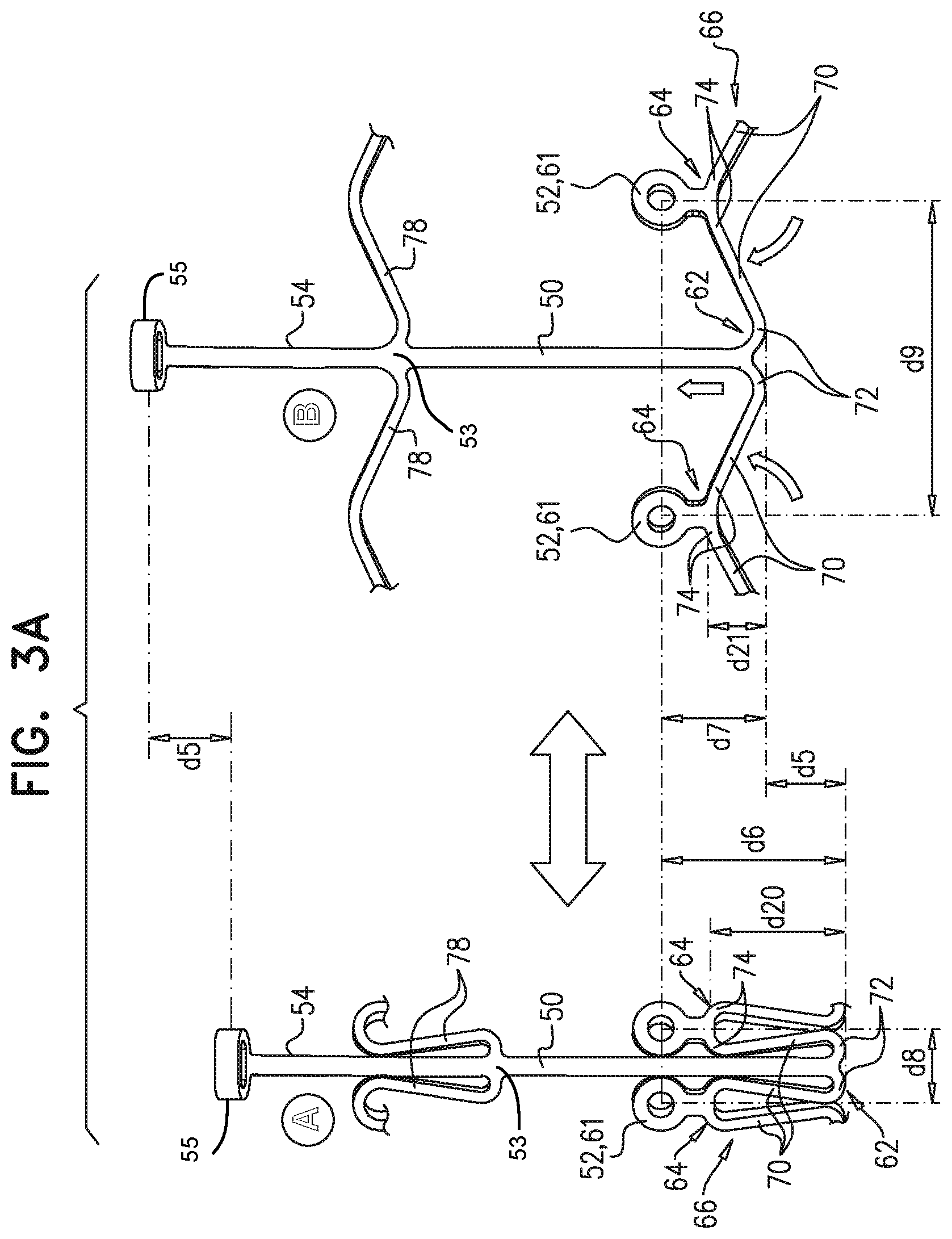
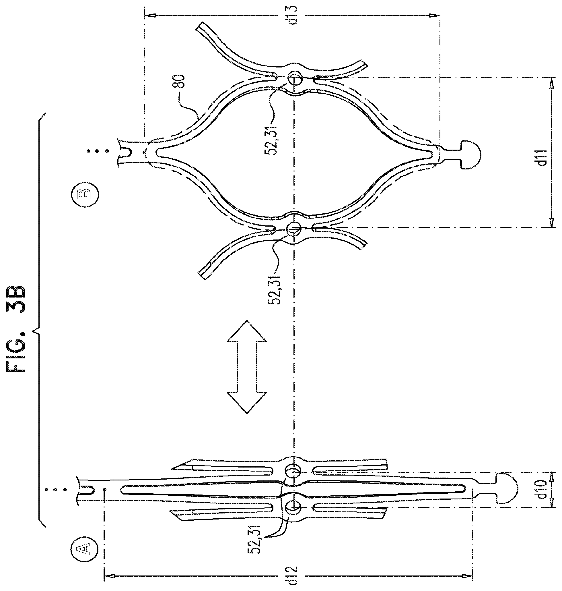
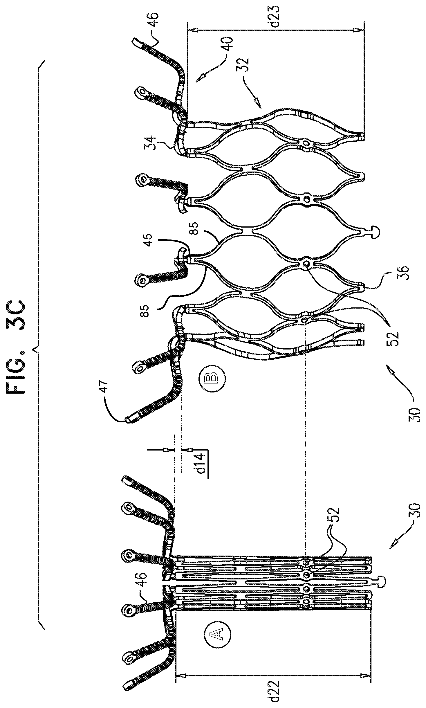
[0086] FIGS. 3A-C are schematic illustrations that show structural changes in a frame assembly during transitioning of the assembly between its compressed and expanded states, in accordance with some embodiments of the disclosure;
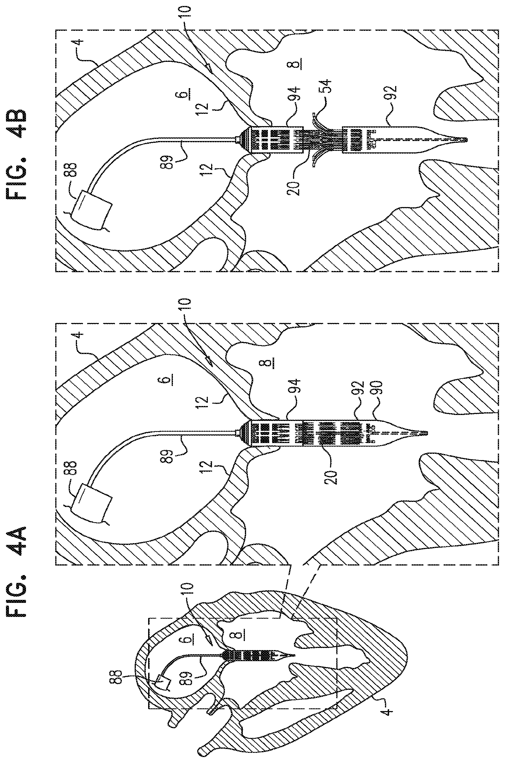
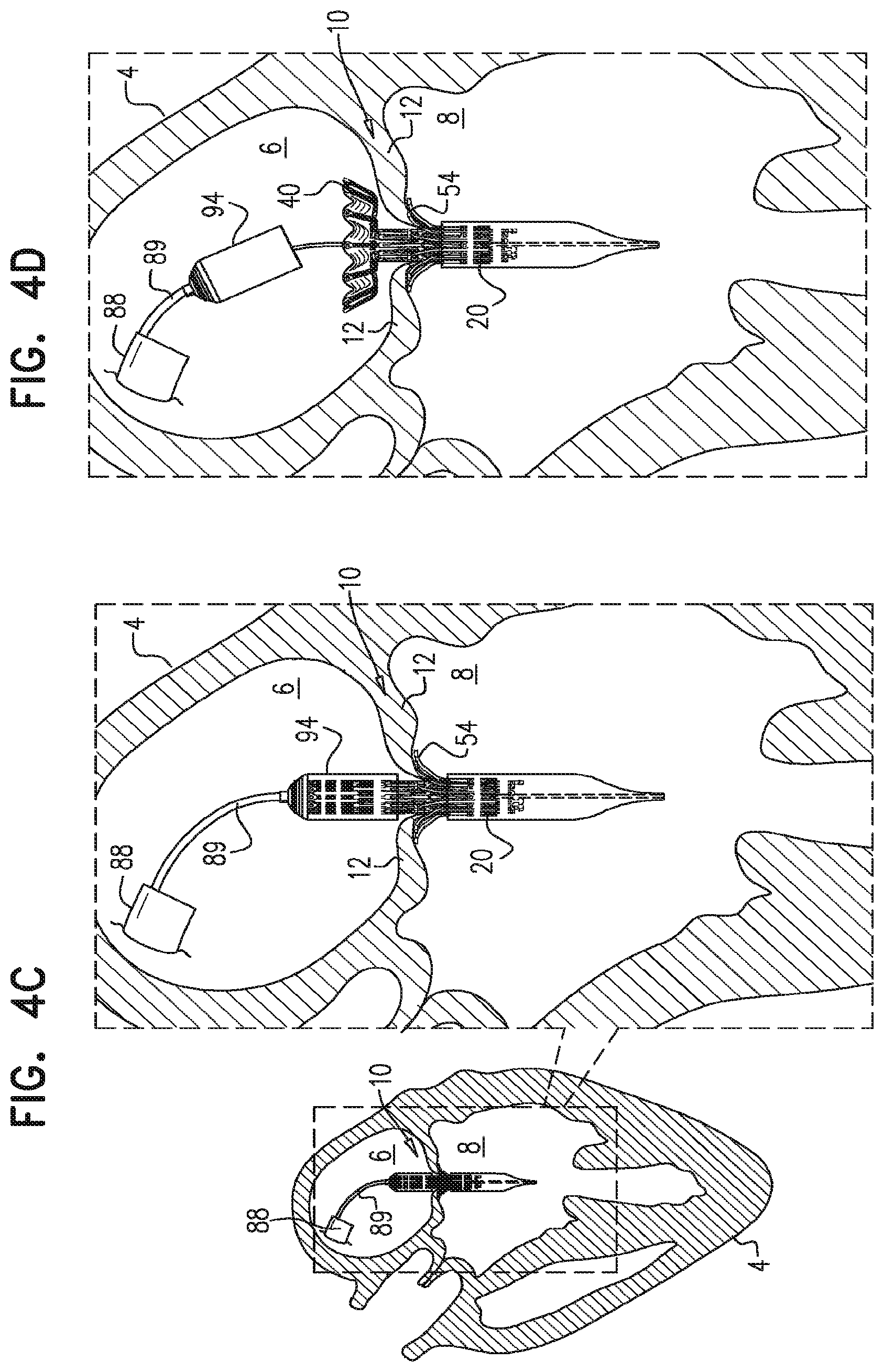
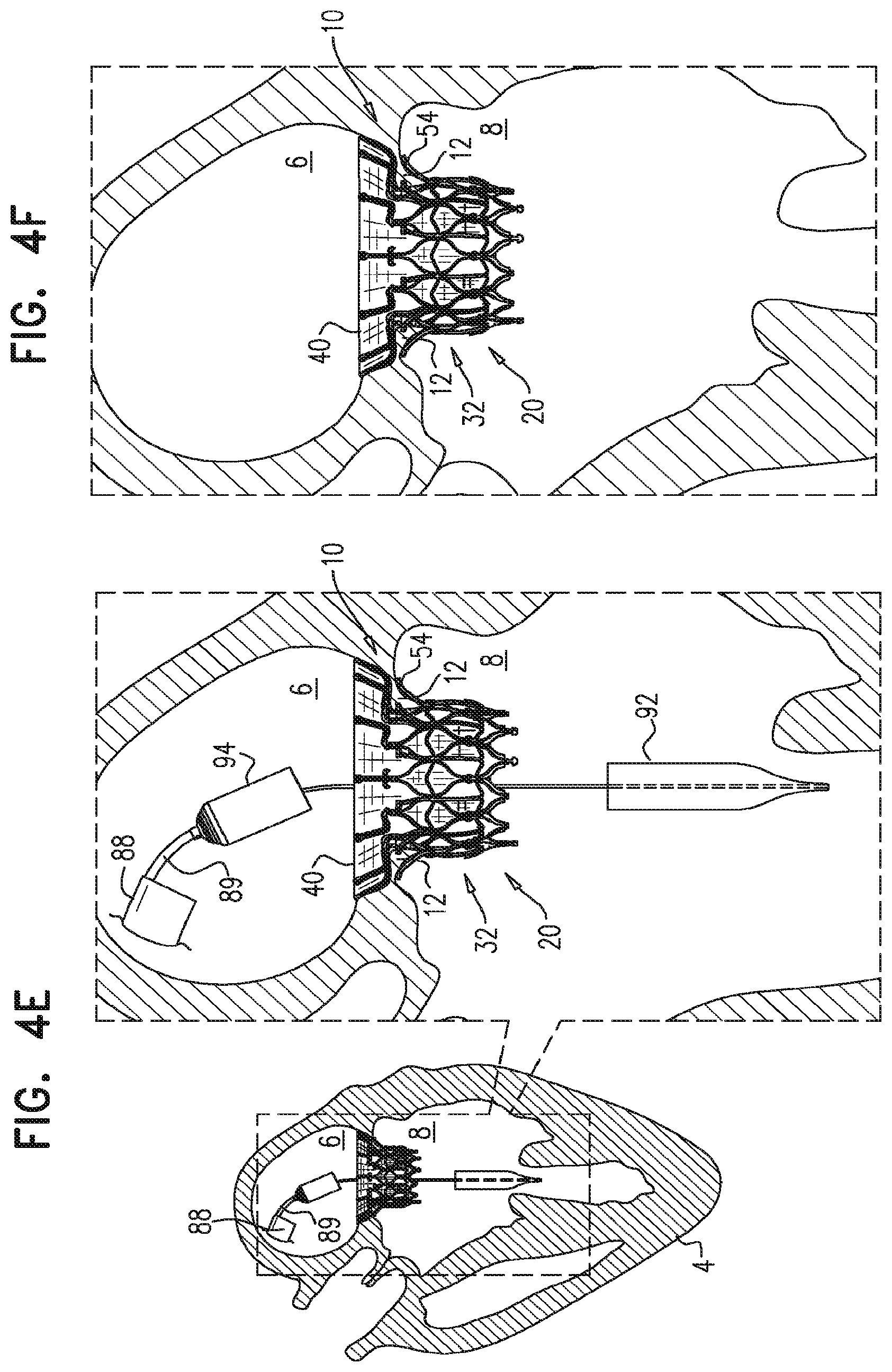
[0087] FIGS. 4A-F are schematic illustrations of implantation of the implant at the native valve, in accordance with some embodiments of the disclosure;
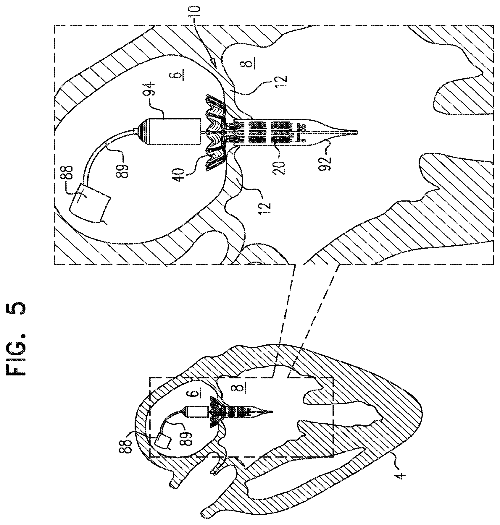
[0088] FIG. 5 is a schematic illustration of a step in the implantation of the implant, in accordance with some embodiments of the disclosure;
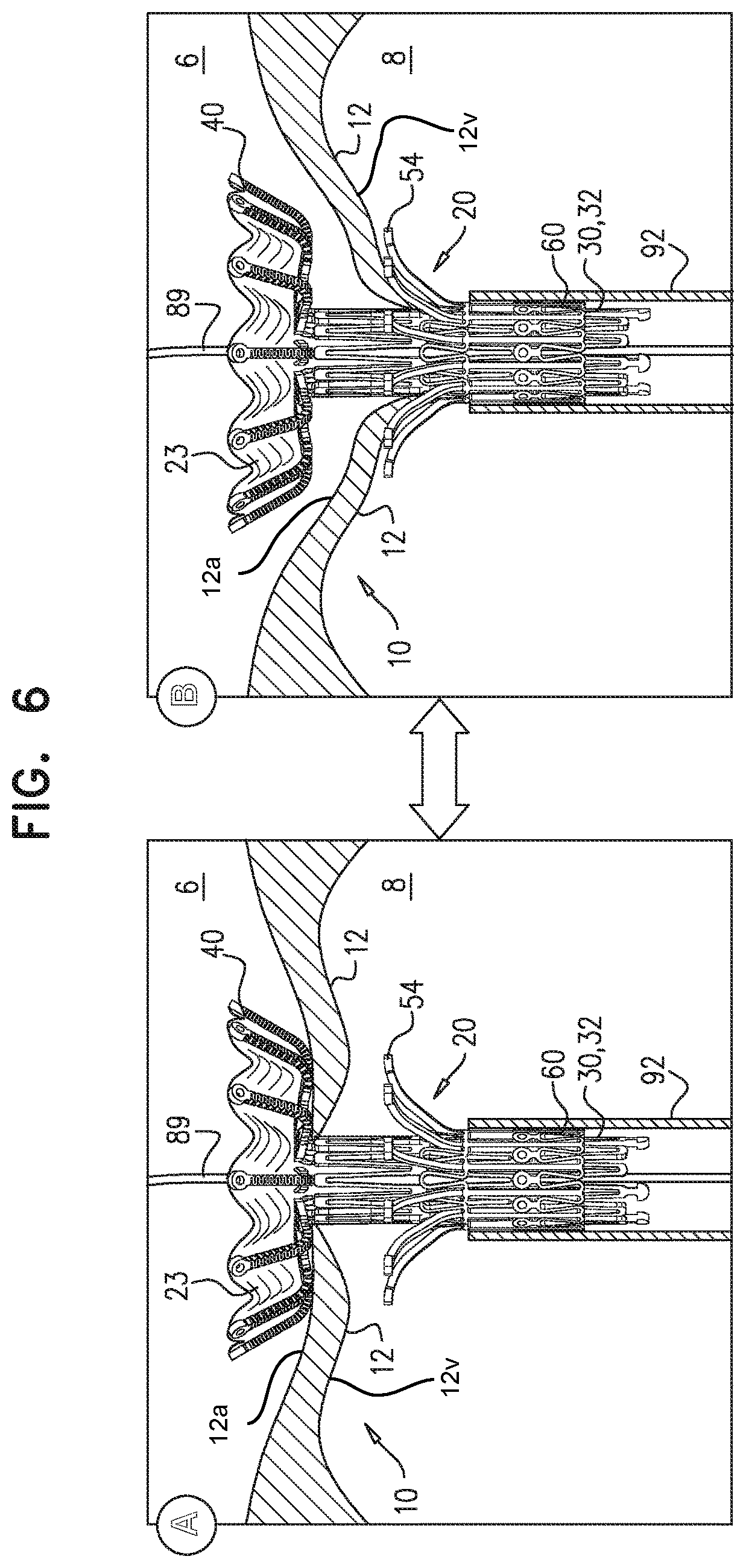
[0089] FIG. 6 is a schematic illustration of the implant, in accordance with some embodiments of the disclosure;
[0090] FIGS. 7A-B and 8A-B are schematic illustrations of frame assemblies of respective implants, in accordance with some embodiments of the disclosure; and
[0091] FIGS. 9A-C are schematic illustrations of an implant including a frame assembly, in accordance with some embodiments of the disclosure.
DETAILED DESCRIPTION OF EMBODIMENTS
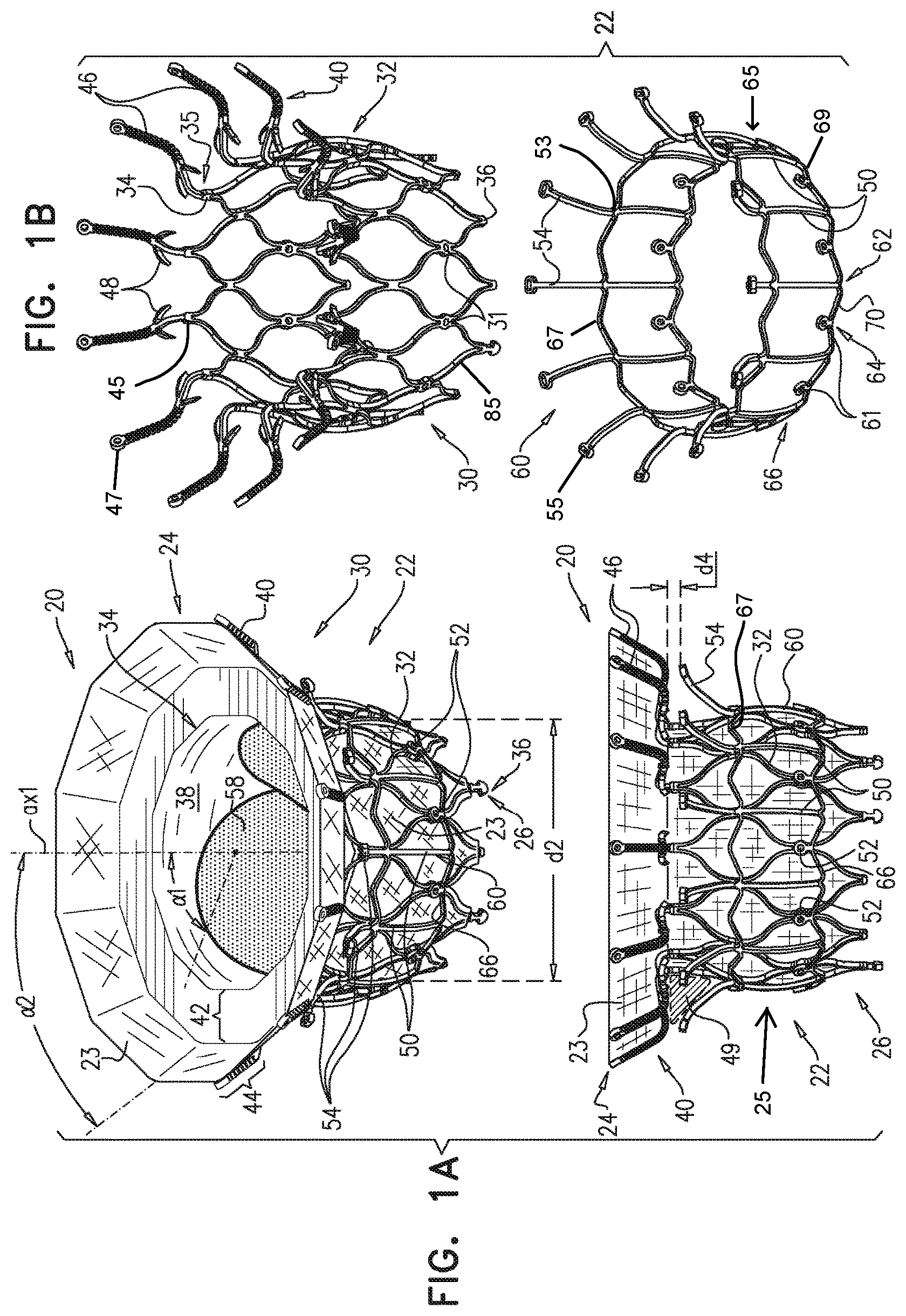
[0092] Reference is made to FIGS. 1A-B and 2A-E, which are schematic illustrations of an implant 20 (alternatively, "prosthetic valve 20") for use with a native valve of a heart of a subject, in accordance with some embodiments of the disclosure. Prosthetic valve 20 includes a frame assembly 22 that has an upstream end 24 (alternatively, "atrial end 24"), a downstream end 26 (alternatively, "ventricular end 26"), and a central longitudinal axis ax1 therebetween. The term "atrial end" may refer to an end of a given feature which is configured to be situated closest to an atrium of the heart when prosthetic valve 20 is implanted therein. For example, in FIGS. 1A, 1B, and 2A-2E, the atrial end of prosthetic valve 20 may be the top end of prosthetic valve 20. Similarly, the term "ventricular end" may refer to an end of a given feature which is configured to be situated closest to a ventricle of the heart when prosthetic valve 20 is implanted therein. For example, in FIGS. 1A, 1B, and 2A-2E, the ventricular end of prosthetic valve 20 may be the bottom end of prosthetic valve 20. Frame assembly 22 includes a valve frame 30 (alternatively, "inner frame 30") that includes a tubular portion 32 (alternatively, "inner frame tubular portion 32") which is constructed of struts 85 and which has an atrial end 34 and a ventricular end 36, and is shaped to define a lumen 38 through the inner frame tubular portion 32 from the atrial end 34 to the ventricular end 36. Inner frame tubular portion 32 circumscribes axis ax1, and thereby defines lumen 38 along the axis. Inner frame 30 further includes an upstream support portion 40, extending from atrial end 34 of inner frame tubular portion 32. Frame assembly 22 further includes at least one leg 50 (alternatively, "ventricular anchor support 50"), coupled to inner frame 30 at (e.g., via) a coupling point 52, and having a tissue-engaging flange 54 (alternatively, "ventricular anchoring leg 54"). As illustrated in FIG. 1B, ventricular anchoring legs 54 may extend from outer frame 60. In particular, and as illustrated in FIGS. 1B and 3A, each ventricular anchoring leg 54 may extend from junction 53 of outer frame 60. Junction 53 may be the intersection between ventricular anchoring leg 54, ventricular anchoring support 50, and connectors 78. Thus, junction 53 may form a point of connection between ventricular anchoring leg 54 and outer frame 60.
[0093] In some embodiments, and as described hereinbelow, ventricular anchor support 50 is part of an outer frame 60, and frames 30 and 60 define respective coupling elements 31 and 61, which are fixed with respect to each other at coupling points 52. As illustrated in FIG. 1A, inner frame 30 may be positioned at least partially within outer frame 60. In some embodiments, frames 30 and 60 are coupled to each other only at coupling points 52 (e.g., only via the fixation of coupling elements 31 and 61 with respect to each other).
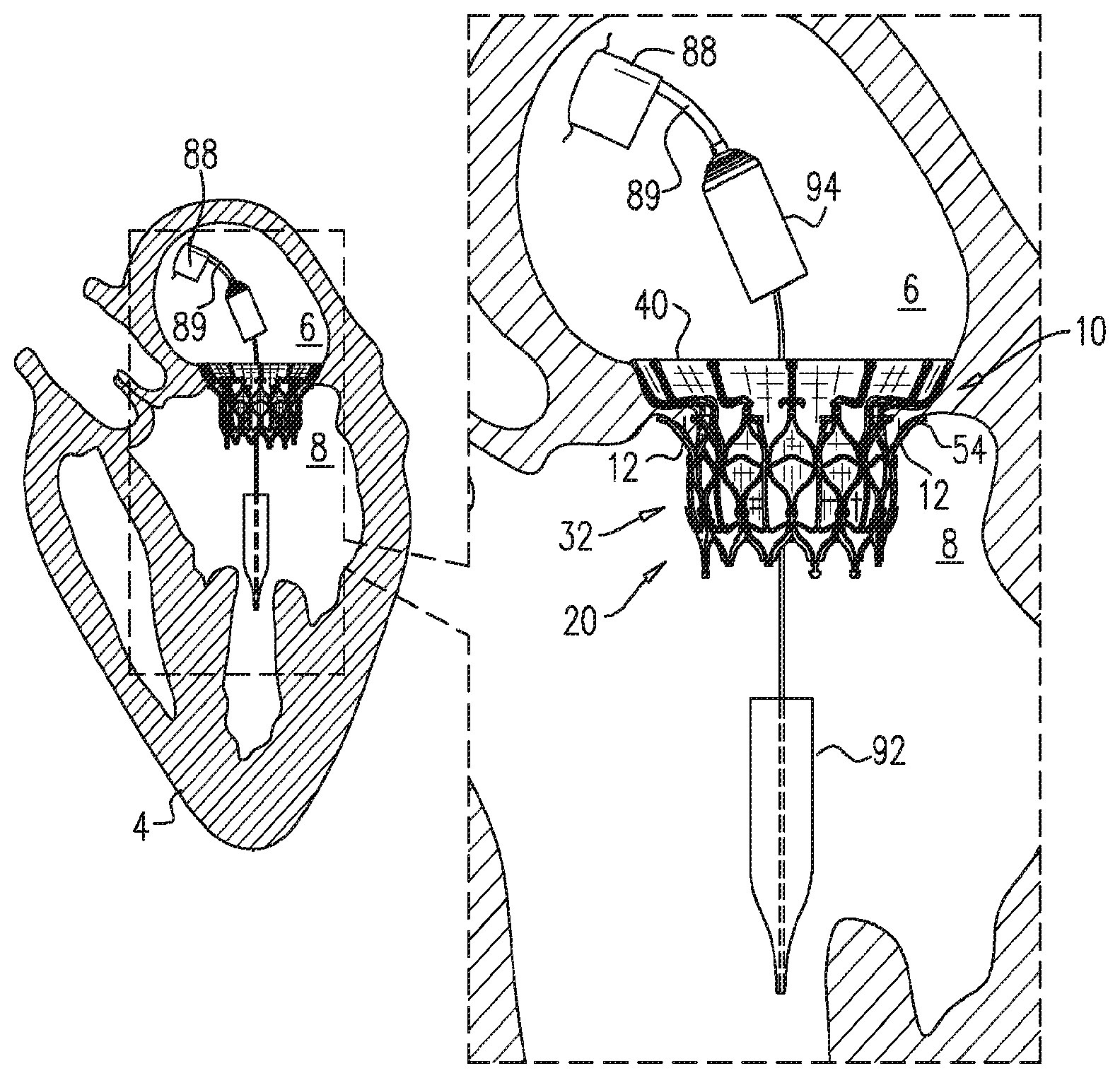
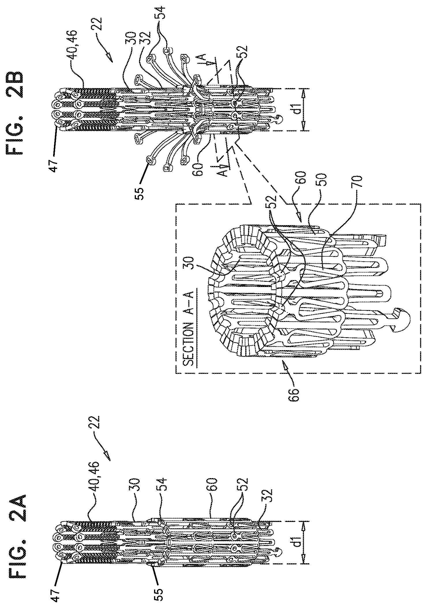
[0094] Prosthetic valve 20 further includes a valve member 58 (e.g., one or more prosthetic leaflets) disposed within lumen 38, and configured to facilitate one-way liquid flow through the lumen from atrial end 34 to ventricular end 36 (e.g., thereby defining the orientation of the atrial and ventricular ends of inner frame tubular portion 32). FIG. 1A shows prosthetic valve 20 in a fully-expanded state, in which frame assembly 22 is in a fully-expanded state. FIG. 1B shows an exploded view of frame assembly 22 in its fully-expanded state. FIGS. 2A-E show respective states of prosthetic valve 20, which will be discussed in more detail hereinbelow with respect to the implantation of the prosthetic valve and the anatomy in which the prosthetic valve is implanted. FIG. 2A shows prosthetic valve 20 in a compressed state in which frame assembly 22 is in a compressed state for percutaneous delivery of the prosthetic valve to the heart of the subject. As illustrated in FIGS. 4A and 4B, frame assembly 22 may be in the compressed state when it is constrained within delivery device 89 during delivery to the heart; thus, the compressed state of frame assembly 22 illustrated in FIG. 2A may also constitute a contracted delivery configuration of the frame assembly 22. In some embodiments, in the contracted delivery configuration, ventricular anchor support 50 (including ventricular anchoring leg 54 thereof) is in a radially constrained state in which the ventricular anchoring leg is generally parallel with axis ax1. For example, ventricular anchor support 50 (including ventricular anchoring leg 54) may be in the delivery configuration and extending in an upstream, atrial direction towards atrium 6 when radially constrained within delivery device 89, as illustrated in FIG. 4A. Further in some embodiments, in the contracted delivery configuration, upstream support portion 40 is generally tubular, collinear with inner frame tubular portion 32 (e.g., extending collinearly from the inner frame tubular portion), and disposed around axis ax1. For example, upstream support portion 40 may be in the delivery configuration when radially constrained within delivery device 89, as illustrated in FIG. 4A.
[0095] The term "atrial direction" may refer to a direction extending upstream from prosthetic valve 20, towards an atrium of the heart. For example, in FIGS. 4A-4E, an "atrial direction" may refer to a direction extending upstream from the valve towards left atrium 6. The term "ventricular direction" may refer to a direction extending downstream from prosthetic valve 20, towards a ventricle of the heart. In some embodiments, an "atrial direction" may be angled radially inward or outward from prosthetic valve 20, so long as it also is angled upstream (towards an atrium) and not downstream (towards a ventricle); that is, an "atrial direction" need not necessarily be parallel to longitudinal axis ax1, although it may be parallel to longitudinal axis ax1 in some embodiments. Similarly, a "ventricular direction" may be angled radially inward or outward from prosthetic valve 20, so long as it also is angled downstream, towards a ventricle. For example, in FIGS. 4A-4F, a "ventricular direction" may refer to a direction extending downstream (downwards in FIGS. 4A-4F) from the valve towards the left ventricle. A "ventricular direction" need not necessarily be parallel to longitudinal axis ax1, although it may be parallel to longitudinal axis ax1 in some embodiments.
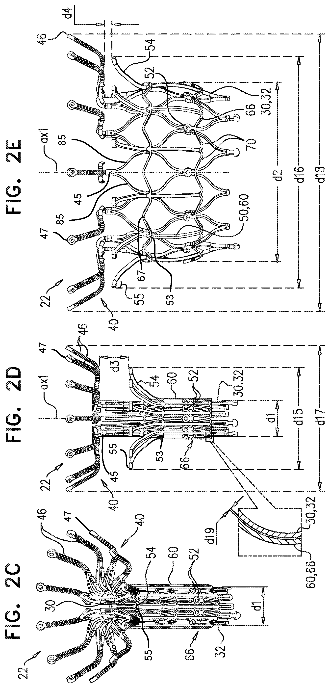
[0096] FIG. 2B shows a state of prosthetic valve 20 in which ventricular anchoring leg 54 of each ventricular anchor support 50, including terminal ends 55 thereof, extends radially away from axis ax1 (e.g., radially away from inner frame tubular portion 32) in an unconstrained configuration. FIG. 2C shows a state of prosthetic valve 20 in which upstream support portion 40 (including the terminal ends 47 of atrial anchoring arms 46) extends radially away from axis ax1 (and thereby radially away from inner frame tubular portion 32) in an unconstrained configuration. FIG. 2D shows a state of prosthetic valve 20 in which both ventricular anchoring leg 54 and upstream support portion 40 extend away from axis ax1 in their respective unconstrained configurations. In the fully-expanded state (FIGS. 1A-B) (that is, an unconstrained configuration of annular valve body 25) both upstream support portion 40 and ventricular anchoring leg 54 extend radially away from axis ax1. In some embodiments, frame assembly 22 is biased (e.g., shape-set) to assume its unconstrained configuration, which is shown in FIG. 2E. Transitioning of prosthetic valve 20 between the respective configurations may be controlled by a delivery apparatus, such as by constraining the prosthetic valve in a contracted delivery configuration within a delivery tube and/or against a control rod, and selectively releasing portions of the prosthetic valve to allow them to expand. As also illustrated in FIGS. 2D and 2E, expansion of annular valve body 25 from the contracted delivery configuration (FIG. 2D) to the fully-expanded, unconstrained configuration (FIG. 2E) may shift points of connection 45 and 53 radially outward.
[0097] In the contracted delivery configuration of frame assembly 22, inner frame tubular portion 32 has a diameter d1, and in the unconstrained configuration, the inner frame tubular portion has a diameter d2 that is greater that diameter d1. For some embodiments, diameter d1 is 4-15 mm, (e.g., 5-11 mm) and diameter d2 is 20-50 mm, (e.g., 23-33 mm). Frame assembly 22 is configured such that increasing the diameter of inner frame tubular portion 32 (e.g., from d1 to d2) causes longitudinal movement of ventricular anchoring leg 54 away from coupling point 52. In the same way, reducing the diameter of inner frame tubular portion 32 (e.g., from d2 to d1) causes longitudinal movement of ventricular anchoring leg 54 toward coupling point 52. It is to be noted that the term "longitudinal movement" (including the specification and the claims) means movement parallel with central longitudinal axis ax1. Therefore longitudinal movement of ventricular anchoring leg 54 away from coupling point 52 means increasing a distance, measured parallel with longitudinal axis ax1, between ventricular anchoring leg 54 and coupling point 52. An example of such a configuration is described in more detail with respect to FIG. 3A.
[0098] Thus, expansion of inner frame tubular portion 32 from its contracted delivery configuration toward its unconstrained configuration increases a circumferential distance between each of coupling points 52 and its adjacent coupling points (e.g., between each of outer-frame coupling elements 61 and its adjacent outer-frame coupling elements) (e.g., from d8 to d9), and moves ventricular anchor supports 50 in a longitudinally upstream direction with respect to the inner frame tubular portion (that is, in an atrial direction).
[0099] In some embodiments, frame assembly 22 is configured such that increasing the diameter of inner frame tubular portion 32 also causes longitudinal movement of upstream support portion 40 toward coupling point 52, e.g., as described in more detail with respect to FIGS. 3B-C. In some embodiments, frame assembly 22 is configured such that increasing the diameter of inner frame tubular portion 32 also causes longitudinal movement of atrial end 34 of inner frame tubular portion 32 toward coupling point 52. In the same way, reducing the diameter of inner frame tubular portion 32 causes longitudinal movement of atrial end 34 away from coupling point 52.
[0100] For some embodiments, upstream support portion 40 includes a plurality of atrial anchoring arms 46 that each extends radially outward from inner frame tubular portion 32 (e.g., from atrial end 34 of the inner frame tubular portion 32). In particular, and as illustrated in FIGS. 1B and 3C, each atrial anchoring arm 46 may extend from junction 45 of inner frame 30. Junction 45 may be the intersection between atrial anchoring arm 46 and struts 85. Thus, junction 45 may form a point of connection between atrial anchoring arm 46 and inner frame 30. In some embodiments, and as illustrated in FIG. 2C, the terminal ends 47 of the arms may deflect radially outward from annular valve body 25 when the atrial anchoring arms 46 assume the unconstrained configuration. Atrial anchoring arms 46 may be flexible. For some such embodiments, atrial anchoring arms 46 are coupled to inner frame tubular portion 32 such that each atrial anchoring arm 46 may deflect independently of adjacent atrial anchoring arms during implantation (e.g., due to anatomical topography).
[0101] For some embodiments, upstream support portion 40 includes a plurality of barbs 48 that extend out of a ventricular surface of the upstream support portion 40. For example, each atrial anchoring arm 46 may include one or more of barbs 48. Barbs 48 press into tissue upstream of the native valve (e.g., into the valve annulus), thereby inhibiting downstream movement of prosthetic valve 20 (in addition to inhibition of downstream movement provided by the geometry of upstream support portion 40).
[0102] One or more surfaces of frame assembly 22 are covered with a covering 23, which may include a flexible sheet, such as a fabric, e.g., including polyester. In some embodiments, covering 23 covers at least part of inner frame tubular portion 32, in some embodiments lining an inner surface of the inner frame tubular portion, and thereby defining lumen 38.
[0103] Further in some embodiments, upstream support portion 40 is covered with covering 23, e.g., extending between atrial anchoring arms 46 to form an annular shape. It is hypothesized that this reduces a likelihood of paravalvular leakage. For such embodiments, excess covering 23 may be provided between atrial anchoring arms 46 of upstream support portion 40, so as to facilitate their independent movement. Although FIG. 1A shows covering 23 covering an atrial side of upstream support portion 40, the covering may additionally or alternatively cover the ventricular side of the upstream support portion. For example, covering 23 may extend over the terminal ends 47 of atrial anchoring arms 46 and down the outside of the atrial anchoring arms 46, or a separate piece of covering may be provided on the ventricular side of the upstream support portion 40.
[0104] Alternatively, each atrial anchoring arm 46 may be individually covered in a sleeve of covering 23, thereby facilitating independent movement of the atrial anchoring arms 46.
[0105] For some embodiments, at least part of ventricular anchor supports 50 (e.g., ventricular anchoring legs 54 thereof) is covered with covering 23.
[0106] In some embodiments, frame assembly 22 includes a plurality of ventricular anchor supports 50 (e.g., two or more supports, e.g., 2-16 supports, such as 4-12 supports, such as 6-12 supports), arranged circumferentially around inner frame 30 (e.g., around the outside of inner frame tubular portion 32). In some embodiments, frame assembly 22 includes a plurality of coupling points 52 at which the ventricular anchor supports 50 are coupled to inner frame 30.
[0107] As described in more detail hereinbelow (e.g., with reference to FIG. 3A), each ventricular anchor support 50 may be coupled to a coupling point 52 via a strut 70. For some embodiments, each ventricular anchor support 50 is coupled to a plurality of (e.g., two) coupling points 52 via a respective plurality of (e.g., two) struts 70. For some such embodiments, frame assembly 22 is arranged such that, in the unconstrained configuration of the frame assembly, ventricular anchor support 50 is disposed, circumferentially with respect to inner frame tubular portion 32, between two struts, and each of the two struts are disposed, circumferentially with respect to the inner frame tubular portion 32, between the ventricular anchor support 50 and a respective coupling point 52.
[0108] For some embodiments, a plurality of (e.g., two) ventricular anchor supports 50 are coupled to each coupling point 52 via a respective plurality of (e.g., two) struts 70. For some such embodiments, frame assembly 22 is arranged such that, in the unconstrained configuration of the frame assembly, coupling point 52 is disposed, circumferentially with respect to inner frame tubular portion 32, between two struts 70, and each of the two struts are disposed, circumferentially with respect to the inner frame tubular portion 32, between the coupling point 52 and a respective ventricular anchor support 50.
[0109] For some embodiments, frame assembly 22 includes an outer frame 60 that circumscribes inner frame tubular portion 32, includes (or defines) the plurality of ventricular anchor supports 50 and the plurality of struts 70, and is coupled to inner frame 30 at the plurality of coupling points 52, such that the plurality of ventricular anchor supports 50 are distributed circumferentially around the inner frame tubular portion. For such embodiments, outer frame 60 includes a ring 66 that is defined by a pattern of alternating peaks 64 and troughs 62, and that in some embodiments circumscribes inner frame tubular portion 32. For example, the ring may include struts 70, extending between the peaks 64 and troughs 62. Peaks 64 are longitudinally closer to atrial end 34 of inner frame tubular portion 32 than to ventricular end 36, and troughs 62 are longitudinally closer to the ventricular end than to the atrial end. (It is to be noted that throughout this disclosure, the term "longitudinally" means with respect to longitudinal axis ax1. For example, "longitudinally closer" means closer along axis ax1 (whether positioned on axis ax1 or lateral to axis ax1), and "longitudinal movement" means a change in position along axis ax1 (which may be in additional to movement toward or away from axis ax1).) Therefore, peaks 64 are closer than troughs 62 to atrial end 34, and troughs 62 are closer than peaks 64 to ventricular end 36. As illustrated in FIG. 1B, outer frame 60 may include multiple rings 66; in embodiments depicted in FIG. 1B, outer frame 60 includes two rings 66 connected by ventricular anchor supports 50. Rings 66 and ventricular anchor supports 50 may form an annular outer frame tubular portion 65. Outer frame tubular portion 65 may have an atrial end 67 and a ventricular end 69, and may circumscribe axis ax1. In some embodiments, atrial end 67 may constitute a portion of the most upstream ring 66 and ventricular end 69 may constitute a portion of the most downstream ring 66. As also illustrated in FIG. 1B, ventricular anchoring legs 54 may extend from outer frame tubular portion 65. For embodiments in which frame 60 includes ring 66, each ventricular anchor support 50 is coupled to the ring (or defined by frame 60) at a respective trough 62.
[0110] In the embodiment shown, the peaks and troughs are defined by ring 66 having a generally zig-zag shape. However, the scope of the disclosure includes ring 66 having another shape that defines peaks and troughs, such as a serpentine or sinusoid shape.
[0111] In some embodiments, inner frame tubular portion 32 and outer frame tubular portion 65 may form annular valve body 25. Annular valve body 25 may circumscribe axis ax1, and atrial anchoring arms 46 and ventricular anchoring legs 54 may extend from annular valve body 25. Annular valve body 25 may have an atrial end, a ventricular end, and an intermediate portion extending between the atrial end and the ventricular end. For example, in embodiments depicted in FIG. 1A, atrial end 34 and ventricular end 36 of inner frame tubular portion 32 may constitute the atrial and ventricular ends of annular valve body 25, respectively. According to such embodiments, the intermediate portion of annular valve body 25 may include portions of annular valve body 25 positioned between atrial end 34 and ventricular end 36. However, one of ordinary skill will understand that this embodiment is merely exemplary, and that other portions of annular valve body 25 may form the atrial and ventricular ends of annular valve body 25. In some embodiments, and as illustrated in FIGS. 1A and 2E, inner frame 30 may extend upstream in an atrial direction beyond the atrial end 67 of outer frame 60.
[0112] For embodiments in which frame assembly 22 has a plurality of coupling points 52, the coupling points (and therefore coupling elements 31 and 61) are disposed circumferentially around the frame assembly (e.g., around axis ax1), in some embodiments on a transverse plane that is orthogonal to axis ax1. This transverse plane is illustrated by the position of section A-A in FIG. 2B. Alternatively, coupling points 52 may be disposed at different longitudinal heights of frame assembly 22, e.g., such that different ventricular anchoring legs 54 are positioned and/or moved differently to others. In some embodiments, coupling points 52 (and therefore coupling elements 31 and 61) are disposed longitudinally between atrial end 24 and ventricular end 26 of frame assembly 22, but not at either of these ends. Further in some embodiments, coupling points 52 are disposed longitudinally between atrial end 34 and ventricular end 36 of inner frame tubular portion 32, but not at either atrial end 34 or ventricular end 36. For example, the coupling points may be more than 3 mm (e.g., 4-10 mm) both from atrial end 34 and from ventricular end 36. It is hypothesized that this advantageously positions the coupling points at a part of inner frame tubular portion 32 that is more rigid than atrial end 34 or ventricular end 36.
[0113] It is to be noted that ventricular anchor support 50 may be expandable into its unconstrained configuration (e.g., a released-leg state) such that ventricular anchoring leg 54 extends away from axis ax1, independently of increasing the diameter of inner frame tubular portion 32 and outer frame tubular portion 65 (e.g., as shown in FIGS. 2B & 2D). Similarly, upstream support portion 40 may be expandable into its unconstrained configuration (e.g., a released-arm state) such that it (e.g., atrial anchoring arms 46 thereof) extends away from axis ax1, independently of increasing the diameter of inner frame tubular portion 32 and outer frame tubular portion 65 (e.g., as shown in FIGS. 2C & 2D). The state shown in FIG. 2D may be considered to be an intermediate state. Therefore, prosthetic valve 20 may be configured such that ventricular anchor supports 50 (e.g., ventricular anchoring legs 54 thereof) and upstream support portion 40 are expandable such that they both extend away from axis ax1, while retaining a distance d3 therebetween. This distance is subsequently reducible to a distance d4 by expanding inner frame tubular portion 32 and outer frame tubular portion 65 (e.g., shown in FIG. 2E).
[0114] For some embodiments, while inner frame tubular portion 32 remains in its contracted delivery configuration, ventricular anchoring leg 54 can extend away from axis ax1 over 40 percent (e.g., 40-80 percent, such as 40-70 percent) of the distance that it extends from the axis subsequent to the expansion of the inner frame tubular portion. For example, for embodiments in which prosthetic valve 20 includes a ventricular anchoring leg on opposing sides of the prosthetic valve, a span d15 of the ventricular anchoring legs while inner frame tubular portion 32 is in its contracted delivery configuration may be at least 40 percent (e.g., 40-80 percent, such as 40-70 percent) as great as a span d16 of the ventricular anchoring legs subsequent to the expansion of the inner frame tubular portion. For some embodiments, span d15 is greater than 15 mm and/or less than 50 mm (e.g., 20-30 mm). For some embodiments, span d16 is greater than 30 mm and/or less than 60 mm (e.g., 40-50 mm). It is to be noted that ventricular anchoring leg 54 is effectively fully expanded, with respect to other portions of ventricular anchor support 50 and/or with respect to inner frame tubular portion 32, before and after the expansion of the inner frame tubular portion.
[0115] Similarly, for some embodiments, while inner frame tubular portion 32 remains in its contracted delivery configuration, upstream support portion 40 (e.g., atrial anchoring arms 46) can extend away from axis ax1 over 30 percent (e.g., 30-70 percent) of the distance that it extends from the axis subsequent to the expansion of the inner frame tubular portion. That is, for some embodiments, a span d17 of the upstream support portion while inner frame tubular portion 32 is in its contracted delivery configuration may be at least 30 percent (e.g., 30-70 percent) as great as a span d18 of the upstream support portion subsequent to the expansion of the inner frame tubular portion. For some embodiments, span d17 is greater than 16 mm (e.g., greater than 20 mm) and/or less than 50 mm (e.g., 30-40 mm). For some embodiments, span d18 is greater than 40 mm and/or less than 65 mm (e.g., 45-56 mm, such as 45-50 mm). It is to be noted that upstream support portion 40 is effectively fully expanded, with respect to inner frame tubular portion 32, before and after the expansion of the inner frame tubular portion.
[0116] It is to be noted that when inner frame tubular portion 32 is expanded, ventricular anchoring legs 54 may translate radially outward from span d15 to span d16 (e.g., without deflecting). In some embodiments upstream support portion 40 behaves similarly (e.g., atrial anchoring arms 46 translated radially outward from span d17 to span d18, e.g., without deflecting). That is, an orientation of each ventricular anchoring leg 54 and/or each atrial anchoring arm 46 with respect to inner frame tubular portion 32 and/or axis ax1 is in some embodiments the same in the state shown in FIG. 2D as it is in the state shown in FIG. 2E. Similarly, in some embodiments an orientation of each ventricular anchoring leg 54 with respect to upstream support portion 40 (e.g., with respect to one or more atrial anchoring arms 46 thereof) is the same before and after expansion of inner frame tubular portion 32.
[0117] For some embodiments, increasing the diameter of inner frame tubular portion 32 from d1 to d2 causes greater than 1 mm and/or less than 20 mm (e.g., 1-20 mm, such as 1-10 mm or 5-20 mm) of longitudinal movement of ventricular anchoring leg 54 away from coupling point 52. For some embodiments, increasing the diameter of inner frame tubular portion 32 from d1 to d2 causes greater than 1 mm and/or less than 20 mm (e.g., 1-20 mm, such as 1-10 mm or 5-20 mm) of longitudinal movement of upstream support portion 40 toward coupling point 52. For some embodiments, distance d3 is 7-30 mm. For some embodiments, distance d4 is 0-15 mm (e.g., 2-15 mm). For some embodiments, increasing the diameter of inner frame tubular portion 32 from d1 to d2 reduces the distance between the upstream support portion and ventricular anchoring legs 54 by more than 5 mm and/or less than 30 mm, such as 5-30 mm (e.g., 10-30 mm, such as 10-20 mm or 20-30 mm). For some embodiments, the difference between d3 and d4 is generally equal to the difference between d1 and d2. For some embodiments, the difference between d3 and d4 is more than 1.2 and/or less than 3 times (e.g., 1.5-2.5 times, such as about 2 times) greater than the difference between d1 and d2.
[0118] For some embodiments, ventricular anchoring legs 54 curve such that a terminal end 55 of each ventricular anchoring leg 54 is disposed at a shallower angle with respect to inner region 42 of upstream support portion 40, than are portions of ventricular anchor support 50 that are closer to ventricular end 26 of frame assembly 22. For some such embodiments, a terminal end 55 of each ventricular anchoring leg 54 may be generally parallel with inner region 42. For some such embodiments, while inner frame tubular portion 32 is in its unconstrained configuration, a terminal end 55 of each ventricular anchoring leg 54 that extends from the terminal end of the ventricular anchoring leg 54 at least 2 mm along the ventricular anchoring leg 54, is disposed within 2 mm of upstream support portion 40. Thus, for some embodiments, while inner frame tubular portion 32 is in its unconstrained configuration, for at least 5 percent (e.g., 5-8 percent, or at least 8 percent) of span 18 of upstream support portion 40, the upstream support portion is disposed within 2 mm of a ventricular anchoring leg 54.
[0119] For some embodiments, in the absence of any obstruction (such as tissue of the valve or covering 23) between ventricular anchoring leg 54 and upstream support portion 40, increasing the diameter of inner frame tubular portion 32 from d1 to d2 causes the ventricular anchoring leg and the upstream support portion to move past each other (e.g., the ventricular anchoring leg 54 may move between atrial anchoring arms 46 of the upstream support portion), such that the ventricular anchoring leg 54 is closer to the atrial end of prosthetic valve 20 than is the upstream support portion, e.g., as shown hereinbelow for frame assemblies 122 and 222, mutatis mutandis. (For embodiments in which upstream support portion 40 is covered by covering 23, ventricular anchoring legs 54 may not pass the covering. For example, in the absence of any obstruction, ventricular anchoring legs 54 may pass between atrial anchoring arms 46, and press directly against covering 23.) It is hypothesized that in some embodiments this configuration applies greater force to the valve tissue being sandwiched, and thereby further facilitates anchoring of the prosthetic valve. That is, for some embodiments, distance d3 is smaller than the sum of distance d5 and a distance d14 (described with reference to FIG. 3C). For some embodiments, increasing the diameter of inner frame tubular portion 32 from d1 to d2 advantageously causes ventricular anchoring legs 54 and upstream support portion 40 to move greater than 3 mm and/or less than 25 mm (e.g., greater than 5 mm and/or less than 15 mm, e.g., 5-10 mm, such as about 7 mm) with respect to each other (e.g., toward each other and then past each other).
[0120] For some embodiments, in the unconstrained configuration of frame assembly 22, upstream support portion 40 has an inner region (e.g., an inner ring) 42 that extends radially outward at a first angle with respect to axis ax1 (and in some embodiments with respect to inner frame tubular portion 32), and an outer region (e.g., an outer ring) 44 that extends, from the inner region, further radially outward from the inner frame tubular portion 32 at a second angle with respect to the inner frame tubular portion 32, the second angle being smaller than the first angle. For example, in some embodiments inner region 42 extends radially outward at an angle alpha_1 of 60-120 degrees (e.g., 70-110 degrees) with respect to axis ax1, and outer region 44 extends radially outward at an angle alpha_2 of 5-70 degrees (e.g., 10-60 degrees) with respect to axis ax1.
[0121] It is to be noted that angles alpha_1 and alpha_2 are measured between the respective region support portion 40, and the portion of axis ax1 that extends in an upstream, atrial direction from the level of frame assembly 22 at which the respective region begins to extend radially outward.
[0122] In some embodiments in which prosthetic valve 20 is configured to be placed at an atrioventricular valve (e.g., a mitral valve or a tricuspid valve) of the subject, region 42 is configured to be placed against the upstream surface of the annulus of the atrioventricular valve, and region 44 is configured to be placed against the walls of the atrium upstream of the valve.
[0123] For some embodiments, outer region 44 is more flexible than inner region 42. For example, and as shown, each atrial anchoring arm 46 may have a different structure in region 44 than in region 42. It is hypothesized that the relative rigidity of region 42 provides resistance against ventricular migration of prosthetic valve 20, while the relative flexibility of region 44 facilitates conformation of upstream support portion 40 to the atrial anatomy.
[0124] For some embodiments, two or more of atrial anchoring arms 46 are connected by a connector (not shown), reducing the flexibility, and/or the independence of movement of the connected atrial anchoring arms relative to each other. For some embodiments, atrial anchoring arms 46 are connected in particular sectors of upstream support portion 40, thereby making these sectors more rigid than sectors in which the atrial anchoring arms 46 are not connected. For example, a relatively rigid sector may be provided to be placed against the posterior portion of the mitral annulus, and a relatively flexible sector may be provided to be placed against the anterior side of the mitral annulus, so as to reduce forces applied by upstream support portion 40 on the aortic sinus.
[0125] For some embodiments, and as shown, coupling points 52 are disposed closer to ventricular end 26 of frame assembly 22 than are ventricular anchoring legs 54, or is upstream support portion 40.
[0126] As described in more detail with respect to FIGS. 4A-F, the movement of ventricular anchoring leg 54 away from coupling point 52 (and movement of upstream support portion 40 toward the coupling point) facilitates the sandwiching of tissue of the native valve (e.g., leaflet and/or annulus tissue) between the ventricular anchoring leg and the upstream support portion, thereby securing prosthetic valve 20 at the native valve.
[0127] In some embodiments, in the contracted delivery configuration of inner frame tubular portion 32, a ventricular end of each ventricular anchor support 50 is longitudinally closer than valve-frame coupling elements 31 to ventricular end 36, and ventricular anchoring leg 54 of each ventricular anchor support 40 is disposed longitudinally closer than the valve-frame coupling elements to atrial end 34. In some embodiments, this is also the case in the unconstrained configuration of inner frame tubular portion 32.
[0128] FIGS. 3A-C show structural changes in frame assembly 22 during transitioning of the assembly between its contracted delivery configuration and unconstrained configuration, in accordance with some embodiments of the disclosure. FIGS. 3A-C each show a portion of the frame assembly, the structural changes thereof being representative of the structural changes that occur in other portions of the frame assembly. FIG. 3A shows a ventricular anchor support 50 and struts 70 (e.g., a portion of outer frame 60), and illustrates the structural changes that occur around outer frame 60. FIG. 3B shows a portion of inner frame 30, and illustrates the structural changes that occur around the inner frame. FIG. 3C shows inner frame 30 as a whole. In each of FIGS. 3A-C, state (A) illustrates the structure while frame assembly 22 (and in particular inner frame tubular portion 32) is in its contracted delivery configuration, and state (B) illustrates the structure while the frame assembly (and in particular inner frame tubular portion 32) is in its unconstrained configuration.
[0129] FIG. 3A shows structural changes in the coupling of ventricular anchor supports 50 to coupling point 52 (e.g., structural changes of outer frame 60) during the transitioning of frame assembly 22 (and in particular inner frame tubular portion 32) between its contracted delivery configuration and unconstrained configuration. Each ventricular anchor support 50 is coupled to inner frame 30 via at least one strut 70, which connects the ventricular anchor support 50 to coupling point 52. In some embodiments, each ventricular anchor support 50 is coupled to inner frame 30 via a plurality of struts 70. A first end 72 of each strut 70 is coupled to ventricular anchor support 50, and a second end 74 of each strut is coupled to a coupling point 52. As described hereinabove, for embodiments in which frame 60 includes ring 66, each ventricular anchor support 50 is coupled to the ring at a respective trough 62. Ring 66 may include struts 70, extending between the peaks and troughs, with each first end 72 at (or close to) a trough 62, and each second end 74 at (or close to) a peak 64.
[0130] In the contracted delivery configuration of frame assembly 22 (and in particular of inner frame tubular portion 32), each strut 70 is disposed at a first angle in which first end 72 is disposed closer than second end 74 to the ventricular end of the frame assembly. Expansion of frame assembly 22 (and in particular of inner frame tubular portion 32) toward its unconstrained configuration causes strut 70 to deflect to a second angle. This deflection moves first end 72 away from the ventricular end of frame assembly 22. That is, in the unconstrained configuration of frame assembly 22, first end 72 is further from the ventricular end of the frame assembly than it is when the frame assembly is in its contracted delivery configuration. This movement is shown as a distance d5 between the position of end 72 in state (A) and its position in state (B). This movement causes the above-described movement of ventricular anchoring legs 54 away from coupling points 52. As shown, ventricular anchoring legs 54 may move the same distance d5 in response to expansion of frame assembly 22.
[0131] For embodiments in which outer frame 60 includes ring 66, the pattern of alternating peaks and troughs may be described as having an amplitude longitudinally between the peaks and troughs, i.e., measured parallel with central longitudinal axis ax1 of frame assembly 22, and the transition between the contracted delivery configuration and unconstrained configuration may be described as follows: In the contracted delivery configuration of frame assembly 22 (and in particular of inner frame tubular portion 32), the pattern of ring 66 has an amplitude d20. In the unconstrained configuration, frame assembly 22 (and in particular of inner frame tubular portion 32), the pattern of ring 66 has an amplitude d21 that is lower than amplitude d20. Because it is at peaks 64 that ring 66 is coupled to inner frame 30 at coupling points 52, and it is at troughs 62 that ring 66 is coupled to ventricular anchor supports 50, this reduction in the amplitude of the pattern of ring 66 moves ventricular anchor supports 50 (e.g., ventricular anchoring legs 54 thereof) longitudinally further from the ventricular end of the frame assembly. The magnitude of this longitudinal movement (e.g., the difference between magnitudes d20 and d21) is equal to d5.
[0132] In some embodiments, distance d5 is the same distance as the distance that ventricular anchoring leg 54 moves away from coupling point 52 during expansion of the frame assembly. That is, a distance between ventricular anchoring leg 54 and the portion of ventricular anchor support 50 that is coupled to strut 70, in some embodiments remains constant during expansion of the frame assembly. For some embodiments, the longitudinal movement of ventricular anchoring leg 54 away from coupling point 52 is a translational movement (e.g., a movement that does not include rotation or deflection of the ventricular anchoring leg 54).
[0133] For some embodiments, a distance d6, measured parallel to axis ax1 of frame assembly 22, between coupling point 52 and first end 72 of strut 70 while assembly 22 is in its contracted delivery configuration, is 3-15 mm. For some embodiments, a distance d7, measured parallel to axis ax1, between coupling point 52 and first end 72 of strut 70 while assembly 22 is in its unconstrained configuration, is 1-5 mm (e.g., 1-4 mm).
[0134] For some embodiments, amplitude d20 is 2-10 mm (e.g., 4-7 mm). For some embodiments, amplitude d21 is 4-9 mm (e.g., 5-7 mm).
[0135] For some embodiments, and as shown, in the unconstrained configuration, first end 72 of strut 70 is disposed closer to the ventricular end of frame assembly 22 than is coupling point 52. For some embodiments, in the unconstrained configuration, first end 72 of strut 70 is disposed further from the ventricular end of frame assembly 22 than is coupling point 52.
[0136] For embodiments in which frame assembly 22 includes a plurality of ventricular anchor supports 50 and a plurality of coupling points 52 (e.g., for embodiments in which the frame assembly includes outer frame 60) expansion of the frame assembly increases a circumferential distance between adjacent coupling points 52, and an increase in a circumferential distance between adjacent ventricular anchor supports 50. FIG. 3A shows such an increase in the circumferential distance between adjacent coupling points 52, from a circumferential distance d8 in the contracted delivery configuration to a circumferential distance d9 in the unconstrained configuration. For some embodiments, distance d8 is 1-6 mm. For some embodiments, distance d9 is 3-15 mm.
[0137] For some embodiments, in addition to being coupled via ring 66 (e.g., struts 70 thereof) ventricular anchor supports 50 are also connected to each other via connectors 78. Connectors 78 allow the described movement of ventricular anchor supports 50 during expansion of frame assembly 22, but may stabilize ventricular anchor supports 50 relative to each other while the frame assembly is in its unconstrained configuration. For example, connectors 78 may bend and/or deflect during expansion of the frame assembly.
[0138] FIGS. 3B-C show structural changes in inner frame 30 during the transitioning of frame assembly 22 between its contracted delivery configuration and unconstrained configuration. Inner frame tubular portion 32 of inner frame 30 is defined by a plurality of cells 80, which are defined by the repeating pattern of the inner frame. When frame assembly 22 is expanded from its contracted delivery configuration toward its unconstrained configuration, cells 80 widen from a width d10 to a width d11 (measured orthogonal to axis ax1 of the frame assembly), and shorten from a height d12 to a height d13 (measured parallel to axis ax1 of the frame assembly). This shortening reduces the overall height (i.e., a longitudinal length between atrial end 34 and ventricular end 36) of inner frame tubular portion 32 from a height d22 to a height d23, and thereby causes the above-described longitudinal movement of upstream support portion 40 toward coupling points 52 by a distance d14 (shown in FIG. 3C). For some embodiments, and as shown, coupling points 52 are disposed at the widest part of each cell.
[0139] Due to the configurations described herein, the distance by which ventricular anchoring legs 54 move with respect to (e.g., toward, or toward-and-beyond) upstream support portion 40 (e.g., atrial anchoring arms 46 thereof), may be greater than the reduction in the overall height of inner frame tubular portion 32 (e.g., more than 20 percent greater, such as more than 30 percent greater, such as more than 40 percent greater). That is, prosthetic valve 20 includes an inner frame 30 that includes an inner frame tubular portion 32 that circumscribes a longitudinal axis ax1 of the inner frame so as to define a lumen 38 along the axis, the inner frame tubular portion 32 having an atrial end 34, a ventricular end 36, a longitudinal length therebetween, and a diameter (e.g., d1 or d2) transverse to the longitudinal axis; a valve member 58, coupled to the inner frame tubular portion 32, disposed within the lumen, and arranged to provide unidirectional upstream-to-downstream (i.e. atrial-to-ventricular) flow of blood through the lumen; an upstream support portion 40, coupled to the inner frame tubular portion 32; and an outer frame 60, coupled to the inner frame tubular portion 32, and including a ventricular anchoring leg 54, wherein the prosthetic valve 20 has a first state (e.g., as shown in FIG. 2D and FIG. 4D) and a second state (e.g., as shown in FIG. 2E and FIG. 4E), in both the first state and the second state, the upstream support portion 40 extends radially outward from the inner frame tubular portion 32, and the ventricular anchoring leg 54 extends radially outward from the inner frame tubular portion 32, and the inner frame tubular portion 32, the upstream support portion 40, and the outer frame 60 are arranged such that transitioning of the prosthetic valve 20 from the first state toward the second state increases the diameter of the inner frame tubular portion 32 by a diameter-increase amount (e.g., the difference between d1 and d2), decreases the length of the inner frame tubular portion 32 by a length-decrease amount (e.g., the difference between d22 and d23), and moves the ventricular anchoring leg 54 a longitudinal distance with respect to (e.g., toward or toward-and-beyond) the upstream support portion 40 (e.g., the difference between d3 and d4), this distance being greater than the length-decrease amount.
[0140] As shown in the figures, inner frame 30 may be coupled to outer frame 60 by coupling between a valve-frame coupling element 31 defined by inner frame 30, and an outer-frame coupling element 61 defined by outer frame 60 (e.g., an outer-frame coupling element is coupled to end 74 of each strut). In some embodiments, elements 31 and 61 are fixed with respect to each other. Each coupling point 52 may therefore be defined as the point at which a valve-frame coupling element and a corresponding outer-frame coupling element 61 are coupled (e.g., are fixed with respect to each other). For some embodiments, and as shown, elements 31 and 61 are eyelets configured to be coupled together by a connector, such as a pin or suture. For some embodiments, elements 31 and 61 are soldered or welded together.
[0141] In some embodiments, and as shown, valve-frame coupling elements 31 are defined by inner frame tubular portion 32, and are disposed circumferentially around central longitudinal axis ax1. Outer-frame coupling elements 61 are coupled to ring 66 (or defined by frame 60, such as by ring 66) at respective peaks 64.
[0142] As shown (e.g., in FIGS. 2A-E), inner frame 30 (e.g., inner frame tubular portion 32 thereof) and outer frame 60 (e.g., ring 66 thereof) are arranged in a close-fitting coaxial arrangement, in both the unconstrained configuration and contracted delivery configuration of frame assembly 22. Ignoring spaces due to the cellular structure of the frames, a radial gap d19 between inner frame 30 (e.g., inner frame tubular portion 32 thereof) and outer frame 60 (e.g., ring 66 thereof) may be less than 2 mm (e.g., less than 1 mm), in both the contracted delivery configuration and unconstrained configuration, and during the transition therebetween. This is facilitated by the coupling between frames 30 and 60, and the behavior, described hereinabove, of frame 60 in response to changes in the diameter of inner frame tubular portion 32 (e.g., rather than solely due to delivery techniques and/or tools). For some embodiments, more than 50 percent (e.g., more than 60 percent) of ring 66 is disposed within 2 mm of inner frame tubular portion 32 in both the contracted delivery configuration and unconstrained configuration, and during the transition therebetween. For some embodiments, more than 50 percent (e.g., more than 60 percent) of outer frame 60, except for ventricular anchoring legs 54, is disposed within 2 mm of inner frame tubular portion 32 in both the contracted delivery configuration and unconstrained configuration, and during the transition therebetween. As illustrated in FIGS. 2A and 2C, ventricular anchoring legs 54 may be substantially flush with inner frame 30 when in the contracted delivery configuration. This may be, at least in part, due to the small distance d19 (illustrated in FIG. 2D) between inner frame 30 and outer frame 60, and due to the fact that ventricular anchoring legs 54 are arranged parallel with axis ax1 when in the contracted delivery configuration (as explained above).
[0143] The structural changes to frame assembly 22 (e.g., to outer frame 60 thereof) are described hereinabove as they occur during (e.g., as a result of) expansion of the frame assembly (in particular inner frame tubular portion 32 thereof). This is the natural way to describe these changes because, as described hereinbelow with respect to FIGS. 4A-6, frame assembly 22 is in its contracted delivery configuration during percutaneous delivery to the implant site, and is subsequently expanded. However, the nature of prosthetic valve 20 may be further understood by describing structural changes that occur during compression of the frame assembly 22 (e.g., a transition from the unconstrained configuration in FIG. 2E to the intermediate state in FIG. 2D), in particular inner frame tubular portion 32 thereof (including if inner frame tubular portion 32 were compressed by application of compressive force to the inner frame tubular portion 32, and not to frame 60 except via the inner frame tubular portion 32 pulling frame 60 radially inward). Such descriptions may also be relevant because prosthetic valve 20 may be compressed (i.e., "crimped") soon before its percutaneous delivery, and therefore these changes may occur while prosthetic valve 20 is in the care of the operating physician.
[0144] For some embodiments, the fixation of peaks 64 to respective sites of inner frame tubular portion 32 is such that compression of the inner frame tubular portion 32 from its unconstrained configuration toward its contracted delivery configuration such that the respective sites of the inner frame tubular portion 32 pull the peaks radially inward via radially-inward tension on coupling points 52 reduces a circumferential distance between each coupling point 52 and its adjacent coupling points 52 (e.g., from d9 to d8), and increases the amplitude of the pattern of ring 66 (e.g., from d21 to d20).
[0145] For some embodiments, the fixation of outer-frame coupling elements 61 to valve-frame coupling elements 31 is such that compression of inner frame tubular portion 32 from its unconstrained configuration toward its contracted delivery configuration such that the valve-frame coupling elements 31 pull the outer-frame coupling elements 61 radially inward reduces a circumferential distance between each outer-frame coupling element 61 and its adjacent outer-frame coupling elements 61 (e.g., from d9 to d8), and increases the amplitude of the pattern of ring 66 (e.g., from d21 to d20).
[0146] For some embodiments, the fixation of peaks 64 to the respective sites of inner frame tubular portion 32 is such that compression of the inner frame tubular portion 32 from its unconstrained configuration toward its contracted delivery configuration pulls the peaks radially inward via radially-inward pulling of the respective sites of the inner frame tubular portion 32 on the peaks, reduces a circumferential distance between each of coupling points 52 and its adjacent coupling points 52 (e.g., from d9 to d8), and increases the amplitude of the pattern of ring 66 (e.g., from d21 to d20), without increasing radial gap d19 between inner frame 30 (e.g., inner frame tubular portion 32 thereof) and the ring 66 by more than 1.5 mm.
[0147] For some embodiments, the fixation of outer-frame coupling elements 61 with respect to valve-frame coupling elements 31 is such that compression of inner frame tubular portion 32 from its unconstrained configuration toward its contracted delivery configuration pulls outer-frame coupling elements 61 radially inward via radially-inward pulling of valve-frame coupling elements 31 on outer-frame coupling elements 61, reduces a circumferential distance between each of the outer-frame coupling elements 61 and its adjacent outer-frame coupling elements 61 (e.g., from d9 to d8), and increases the amplitude of the pattern of ring 66 (e.g., from d21 to d20), without increasing radial gap d19 between inner frame 30 (e.g., inner frame tubular portion 32 thereof) and the ring 66 by more than 1.5 mm.
[0148] Reference is made to FIGS. 4A-F, which are schematic illustrations of implantation of prosthetic valve 20 at a native valve 10 of a heart 4 of a subject, in accordance with some embodiments of the disclosure. Valve 10 is shown as a mitral valve of the subject, disposed between a left atrium 6 and a left ventricle 8 of the subject. However prosthetic valve 20 may be implanted at another heart valve of the subject, mutatis mutandis. Similarly, although FIGS. 4A-F show prosthetic valve 20 being delivered transseptally via a sheath 88, the prosthetic valve 20 may alternatively be delivered by any other suitable route, such as transatrially, or transapically.
[0149] Prosthetic valve 20 is delivered, in its contracted delivery configuration, to native valve 10 using a delivery tool 89 that is operable from outside the subject (FIG. 4A). In some embodiments, prosthetic valve 20 is delivered within a delivery capsule 90 of tool 89, which retains the prosthetic valve 20 in its contracted delivery configuration. A transseptal approach, such as a transfemoral approach, is shown. In some embodiments, prosthetic valve 20 is positioned such that at least ventricular anchoring legs 54 are disposed downstream of (that is, in a ventricular direction from) the native valve (i.e., within ventricle 8). At this stage, frame assembly 22 of prosthetic valve 20 is as shown in FIG. 2A.
[0150] Subsequently, ventricular anchoring legs 54 are allowed to protrude radially outward into their unconstrained configuration, as described hereinabove, e.g., by releasing them from capsule 90 (FIG. 4B), for example within ventricle 8. For example, and as shown, capsule 90 may include a distal capsule-portion 92 and a proximal capsule-portion 94, and the distal capsule-portion may be moved distally with respect to prosthetic valve 20, so as to expose ventricular anchoring legs 54. At this stage, frame assembly 22 of prosthetic valve 20 is as shown in FIG. 2B, in which annular valve body 25 and upstream support portion 40 remain in their contracted delivery configurations.
[0151] Subsequently, prosthetic valve 20 is moved upstream in an atrial direction, such that upstream support portion 40, in its contracted delivery configuration, is disposed upstream of (that is, in an atrial direction from) leaflets 12 (i.e., within atrium 6). For some embodiments, the upstream movement of prosthetic valve 20 causes ventricular anchoring legs 54 to engage the ventricular side of leaflets 12. However, because of the relatively large distance d3 provided by prosthetic valve 20 (described hereinabove), in some embodiments it may not be necessary to move the prosthetic valve 20 so far upstream that ventricular anchoring legs 54 tightly engage leaflets 12 and/or pull the leaflets upstream of the valve annulus. Upstream support portion 40 is then allowed to expand such that it protrudes radially outward into its unconstrained configuration, as described hereinabove, e.g., by releasing it from capsule 90 (FIG. 4D), for example within atrium 6. For example, and as shown, proximal capsule-portion 94 may be moved proximally with respect to prosthetic valve 20, so as to expose upstream support portion 40. At this stage, frame assembly 22 of prosthetic valve 20 is as shown in FIG. 2D, in which distance d3 exists between upstream support portion 40 and ventricular anchoring legs 54, the ventricular anchoring legs have span d15, the upstream support portion has span d17, and (iv) inner frame tubular portion 32 has diameter d1. Put another way, annular valve body 25 remains in the contracted delivery configuration.
[0152] In some embodiments, expansion of frame assembly 22 is inhibited by distal capsule-portion 92 (e.g., by inhibiting expansion of inner frame tubular portion 32), and/or by another portion of delivery tool 89 (e.g., a portion of the delivery tool that is disposed within lumen 38).
[0153] Subsequently, prosthetic valve 20 is allowed to expand toward its unconstrained configuration, as illustrated in FIG. 4E, while upstream support portion 40 is positioned within atrium 6 and ventricular anchoring legs 54 are positioned within ventricle 8. As a result, annular valve frame 25 radially expands and inner frame tubular portion 32 widens to diameter d2, and the distance between upstream support portion 40 and ventricular anchoring legs 54 reduces to distance d4 (FIG. 4E). This sandwiches tissue of valve 10 (in some embodiments including annular tissue and/or leaflets 12) between upstream support portion 40 and ventricular anchoring legs 54, thereby securing prosthetic valve 20 at the valve. FIG. 4F shows delivery capsule 90 having been removed from the body of the subject, leaving prosthetic valve 20 in place at valve 10.
[0154] As described hereinabove, prosthetic valve 20 is configured such that when inner frame tubular portion 32 is expanded, ventricular anchoring legs 54 and upstream support portion 40 move a relatively large distance toward each other. This enables distance d3 to be relatively large, while distance d4 is sufficiently small to provide effective anchoring. As also described hereinabove, prosthetic valve 20 is configured such that ventricular anchoring legs 54 and upstream support portion 40 can extend radially outward a relatively large distance while inner frame tubular portion 32 remains compressed. It is hypothesized that for some embodiments, these configurations (independently and/or together) facilitate effective anchoring of prosthetic valve 20, by facilitating placement of a relatively large proportion of valve tissue (e.g., leaflets 12) between the ventricular anchoring legs 54 and the upstream support portion prior to expanding inner frame tubular portion 32 and sandwiching the valve tissue.
[0155] It is further hypothesized that the relatively great radially-outward extension of ventricular anchoring legs 54 and upstream support portion 40 prior to expansion of inner frame tubular portion 32, further facilitates the anchoring/sandwiching step by reducing radially-outward pushing of the valve tissue (e.g., leaflets 12) during the expansion of the inner frame tubular portion 32, and thereby increasing the amount of valve tissue that is sandwiched.
[0156] It is yet further hypothesized that this configuration of prosthetic valve 20 facilitates identifying correct positioning of the prosthetic valve 20 (i.e., with upstream support portion 40 upstream of leaflets 12 and ventricular anchoring legs 54 downstream of the leaflets) prior to expanding inner frame tubular portion 32 and sandwiching the valve tissue.
[0157] As shown in FIG. 1A, for some embodiments, in the unconstrained configuration of frame assembly 22, prosthetic valve 20 defines a toroidal space 49 between ventricular anchoring legs 54 and upstream support portion 40 (e.g., a space that is wider than distance d4). For example, space 49 may have a generally triangular cross-section. It is hypothesized that for some such embodiments, in addition to sandwiching tissue of the native valve between upstream support portion 40 and ventricular anchoring legs 54 (e.g., the terminal ends 55 of the ventricular anchoring legs 54), space 49 advantageously promotes tissue growth therewithin (e.g., between leaflet tissue and covering 23), which over time further secures prosthetic valve 20 within the native valve 10.
[0158] Reference is now made to FIG. 5, which is a schematic illustration of a step in the implantation of prosthetic valve 20, in accordance with some embodiments of the disclosure. Whereas FIGS. 4A-F show an implantation technique in which ventricular anchoring legs 54 are expanded prior to upstream support portion 40, in some embodiments the upstream support portion is expanded prior to the ventricular anchoring legs 54. FIG. 5 shows a step in such an application.
[0159] Reference is again made to FIGS. 2A-5. As noted hereinabove, prosthetic valve 20 may be implanted by causing ventricular anchoring legs 54 to radially protrude before causing upstream support portion 40 to radially protrude, or may be implanted by causing the upstream support portion to protrude before causing the ventricular anchoring legs 54 to protrude. For some embodiments, prosthetic valve 20 is thereby configured to be deliverable in a downstream, ventricular direction (e.g., transseptally, as shown, or transapically) or in an upstream, atrial direction (e.g., transapically or via the aortic valve). Thus, for some embodiments, an operating physician may decide which delivery route is preferable for a given application (e.g., for a given subject, and/or based on available equipment and/or expertise), and prosthetic valve 20 is responsively prepared for the chosen delivery route (e.g., by loading the prosthetic valve into an appropriate delivery tool).
[0160] It is to be noted that for some embodiments, downstream delivery of prosthetic valve 20 may be performed by expanding ventricular anchoring legs 54 first (e.g., as shown in FIGS. 4A-F) or by expanding upstream support portion 40 first (e.g., as shown in FIG. 5). Similarly, in some embodiments upstream delivery of prosthetic valve 20 may be performed by upstream support portion 40 first, or by expanding ventricular anchoring legs 54 first.
[0161] Reference is now made to FIG. 6, which is a schematic illustration of prosthetic valve 20, in the state and position shown in FIG. 4D, in accordance with some embodiments of the disclosure. For some embodiments, while prosthetic valve 20 is in the state and position shown in FIG. 4D, leaflets 12 of valve 10 are able to move, at least in part in response to beating of the heart. Frame (A) shows leaflets 12 during ventricular systole, in which the atrial side 12a of the leaflets 12 may contact the unconstrained atrial anchoring arms 46. Frame (B) shows the leaflets during ventricular diastole, in which the ventricular side 12v of the leaflets 12 may contact the unconstrained ventricular anchoring legs 54. For some such embodiments, blood is thereby able to flow from atrium 6 to ventricle 8, between leaflets 12 and prosthetic valve 20. It is hypothesized that this advantageously facilitates a more relaxed implantation procedure, e.g., facilitating retaining of prosthetic valve 20 in this state and position for a duration of greater than 8 minutes. During this time, imaging techniques may be used to verify the position of prosthetic valve 20, and/or positioning of leaflets 12 between upstream support portion 40 and ventricular anchoring legs 54.
[0162] Reference is made to FIGS. 7A-B and 8A-B, which are schematic illustrations of frame assemblies 122 and 222 of respective prosthetic valves, in accordance with some embodiments of the disclosure. Except where noted otherwise, frame assemblies 122 and 222 may be identical to frame assembly 22, mutatis mutandis. Elements of frame assemblies 122 and 222 share the name of corresponding elements of frame assembly 22. Additionally, except where noted otherwise, the prosthetic valves to which frame assemblies 122 and 222 belong are similar to prosthetic valve 20, mutatis mutandis.
[0163] Frame assembly 122 includes an inner frame 130 that includes an inner frame tubular portion 132 and an upstream support portion 140 that may include a plurality of atrial anchoring arms 146, and an outer frame 160 that circumscribes the inner frame, and includes a plurality of ventricular anchor supports 150 that each include a ventricular anchoring leg 154. In some embodiments, outer frame 160 includes a ring 166 to which ventricular anchor supports 150 are coupled. Ring 166 is defined by a pattern of alternating peaks and troughs, the peaks being fixed to frame 130 at respective coupling points 152, e.g., as described hereinabove for frame assembly 22, mutatis mutandis.
[0164] Frame assembly 222 includes an inner frame 230 that includes an inner frame tubular portion 232 and an upstream support portion 240 that may include a plurality of atrial anchoring arms 246, and an outer frame 260 that circumscribes the inner frame, and includes a plurality of ventricular anchor supports 250 that each include a ventricular anchoring leg 254. In some embodiments, outer frame 260 includes a ring 266 to which ventricular anchor supports 250 are coupled. Ring 266 is defined by a pattern of alternating peaks and troughs, the peaks being fixed to frame 230 at respective coupling points 252, e.g., as described hereinabove for frame assembly 22, mutatis mutandis.
[0165] Whereas atrial anchoring arms 46 of frame assembly 22 are shown as extending from atrial end 34 of inner frame tubular portion 32, atrial anchoring arms 146 and 246 of frame assemblies 122 and 222, respectively, extend from sites further downstream. (This difference may also be made to frame assembly 22, mutatis mutandis.) Inner frame tubular portions 32, 132 and 232 are each defined by a repeating pattern of cells that extends around the central longitudinal axis. In some embodiments, and as shown, inner frame tubular portions 32, 132 and 232 are each defined by two stacked, tessellating rows of cells. In the unconstrained configuration of each inner frame tubular portion, these cells may be narrower at their atrial and ventricular extremities than midway between these extremities. For example, and as shown, the cells may be roughly diamond or astroid in shape. In frame assembly 22, each atrial anchoring arm 46 is attached to and extends from a site 35 that is at the atrial extremity of cells of the atrial row. In contrast, in frame assemblies 122 and 222, each atrial anchoring arm 146 or 246 is attached to and extends from a site 135 (assembly 122) or 235 (assembly 222) that is at the connection between two adjacent cells of the atrial row (alternatively described as being at the atrial extremity of cells of the ventricular row).
[0166] It is hypothesized by the inventors that this lower (that is, further downstream) position of the atrial anchoring arms 146, 246, while maintaining the length of the lumen of the inner frame tubular portion 132, 232, advantageously reduces the distance that the inner frame tubular portion 132, 232 (i.e., the ventricular end thereof) extends into the ventricle of the subject, and thereby reduces a likelihood of inhibiting blood flow out of the ventricle through the left ventricular outflow tract. It is further hypothesized that this position of the atrial anchoring arms 146, 246 reduces radial compression of the inner frame tubular portion 132, 232 by movement of the heart, due to greater rigidity of the inner frame tubular portion 132, 232 at sites 135 and 235 (which is supported by two adjacent cells) than at site 35 (which is supported by only one cell).
[0167] As shown, in the unconstrained configuration of frame assemblies 22, 122 and 222, the ventricular anchor supports (50, 150 and 250, respectively) are circumferentially staggered with the atrial anchoring arms of the upstream support portion (46, 146 and 246, respectively). This allows the ventricular anchor supports to move in an upstream, atrial direction between the atrial anchoring arms during expansion of the inner frame tubular portion (32, 132 and 232, respectively), facilitating application of greater sandwiching force on tissue of the native valve. The lower position of the atrial anchoring arms of assemblies 122 and 222 includes circumferentially shifting the position of the atrial anchoring arms by the width of half a cell. In order to maintain the circumferential staggering of the atrial anchoring arms and ventricular anchor supports, rings 166 and 266 (and thereby ventricular anchor supports 150 and 250) are circumferentially shifted correspondingly. As a result, whereas the peaks of ring 66 generally align with connections between adjacent cells of the ventricular row of cells of inner frame tubular portion 32 (and are fixed to these sites), the peaks of rings 166 and 266 are generally aligned midway between these sites (i.e., at spaces of the cellular structure of the inner frame tubular portion). An appendages 168 (for assembly 122) or 268 (for assembly 222) facilitate fixing of the peak with respect to the tubular structure.
[0168] For assembly 122, appendages 168 are defined by inner frame 130 (e.g., by inner frame tubular portion 132 thereof) and extend (in a downstream direction) to the peaks of ring 166, to which they are fixed. For example, each appendage 168 may define a valve-frame coupling element 131 that is fixed to a respective outer-frame coupling element 161 defined by outer frame 260. In some embodiments, appendages 168 extend from sites 135. In some embodiments, appendages 168 are integral with inner frame tubular portion 132 and/or in-plane with the inner frame tubular portion (e.g., are part of its tubular shape).
[0169] For assembly 222, appendages 268 are defined by outer frame 260, and extend (e.g., in an upstream, atrial direction) from the peaks of ring 266. In some embodiments, appendages 268 extend to sites 235, to which they are fixed. For example, each appendage 268 may define an outer-frame coupling element 261 that is fixed to a respective valve-frame coupling element 231 defined by inner frame 230 (e.g., by inner frame tubular portion 232 thereof). In some embodiments, appendages 268 are integral with outer frame 260 and/or in-plane with adjacent portions of outer frame 260, such as ring 266.
[0170] Therefore, frame assembly 122 defines a hub at site 135, and frame assembly 222 defines a hub at site 235. For some embodiments, apparatus therefore includes a plurality of prosthetic valve leaflets; and a frame assembly, including an inner frame tubular portion 132, 232 defined by a repeating pattern of cells, the inner frame tubular portion extending circumferentially around longitudinal axis ax1 so as to define a longitudinal lumen, the prosthetic valve leaflets coupled to the inner frame and disposed within the lumen; an outer frame 160, 260 including a plurality of ventricular anchor supports 150, 250 distributed circumferentially around the inner frame tubular portion, each ventricular anchor support 50 having a ventricular anchoring leg 154, 254; an upstream support portion 140, 240 that includes a plurality of atrial anchoring arms 146, 246 that extend radially outward from the inner frame tubular portion; and a plurality of appendages 168, 268, each having a first end that defines a coupling element 161, 261 via which the inner frame tubular portion is coupled to the outer frame, and a second end; wherein the frame assembly defines a plurality of hubs 135, 235 distributed circumferentially around the longitudinal axis on a plane that is transverse to longitudinal axis ax1, each hub defined by convergence and connection of, two adjacent cells of the inner frame tubular portion, an atrial anchoring arm of the plurality of atrial anchoring arms, and an appendage of the plurality of appendages.
[0171] Reference is made to FIGS. 9A-C, which are schematic illustrations of a prosthetic valve 320 including a frame assembly 322, in accordance with some embodiments of the disclosure. Except where noted otherwise, frame assembly 322 is identical to frame assembly 122, and prosthetic valve 300 is identical to the prosthetic valve to which frame assembly 122 belongs, mutatis mutandis. FIG. 9A is a side-view of prosthetic valve 320, and FIG. 9B is an isometric bottom-view of the prosthetic valve.
[0172] Frame assembly 122 includes an inner frame 330 that includes an inner frame tubular portion 332 and an upstream support portion 340 that may include a plurality of atrial anchoring arms 346, and an outer frame 360 that circumscribes the inner frame, and includes a plurality of ventricular anchor supports 350 that each include a ventricular anchoring leg 354. In some embodiments, outer frame 360 includes a ring 366 to which ventricular anchor supports 350 are coupled. Ring 366 is defined by a pattern of alternating peaks and troughs, the peaks being fixed to frame 330 at respective coupling points 352, e.g., as described hereinabove for frame assembly 22 and/or frame assembly 122, mutatis mutandis.
[0173] Frame assembly 322 includes an annular upstream support portion 340 that has an inner portion 342 that extends radially outward from the upstream portion (e.g., the atrial end) of inner frame tubular portion 332. Upstream support portion 340 further includes one or more fabric pockets 344 disposed circumferentially around inner portion 342, each pocket of the one or more pockets having an opening that faces a downstream, ventricular direction (i.e., generally toward the ventricular end of prosthetic valve 320). In the figures, upstream support portion 340 has a single toroidal pocket 344 that extends circumferentially around inner portion 342.
[0174] In some embodiments, a covering 323 (e.g., similar to covering 23, described hereinabove, mutatis mutandis) is disposed over atrial anchoring arms 346, thereby forming pocket 344. Further in some embodiments, atrial anchoring arms 346 are shaped to form pocket 344 from covering 323. For example, and as shown, atrial anchoring arms 346 may curve to form a hook-shape.
[0175] For some embodiments, portion 340 has a plurality of separate pockets 344, e.g., separated at atrial anchoring arms 346. For some such embodiments, covering 323 is loosely-fitted (e.g., baggy) between radially-outward parts of atrial anchoring arms 346, e.g., compared to inner portion 342, in which the covering is more closely-fitted between radially-inward parts of the atrial anchoring arms.
[0176] FIG. 9C shows prosthetic valve 320 implanted at native valve 10. Pocket 344 is in some embodiments shaped and arranged to billow in response to perivalvular flow 302 of blood in an upstream, atrial direction. If ventricular systole forces blood in ventricle 8 between prosthetic valve 320 and native valve 10, that blood inflates pocket 344 and presses it (e.g., covering 323 and/or the radially-outward part of atrial anchoring arm 346) against tissue of atrium 6 (e.g., against the atrial wall), thereby increasing sealing responsively. It is hypothesized by the inventors that the shape and orientation of pocket 344 (e.g., the hook-shape of atrial anchoring arms 346) facilitates this pressing radially-outward in response to the pocket's receipt of upstream-flowing blood.
[0177] Pocket(s) 344 may be used in combination with any of the prosthetic valves described herein, mutatis mutandis.
[0178] Reference is again made to FIGS. 1A-9C. It is to be noted that unless specifically stated otherwise, the term "radially outward" (e.g., used to describe upstream support portion 40 and ventricular anchoring legs 54) means portions of the element are disposed progressively further outward from a central point (such as longitudinal axis ax1 or inner frame tubular portion 32), but does not necessarily mean disposed at 90 degrees with respect to longitudinal axis ax1. For example, ventricular anchoring legs 54 may extend radially outward at 90 degrees with respect to longitudinal axis ax1, but may alternatively extend radially outward at a shallower angle with respect to the longitudinal axis.
[0179] It will be appreciated by persons skilled in the art that the present disclosure is not limited to what has been particularly shown and described hereinabove. Rather, the scope of the present disclosure includes both combinations and subcombinations of the various features described hereinabove, as well as variations and modifications thereof that are not in the prior art, which would occur to persons skilled in the art upon reading the foregoing description.
* * * * *
D00000
D00001
D00002
D00003
D00004
D00005
D00006
D00007
D00008
D00009
D00010
D00011
D00012
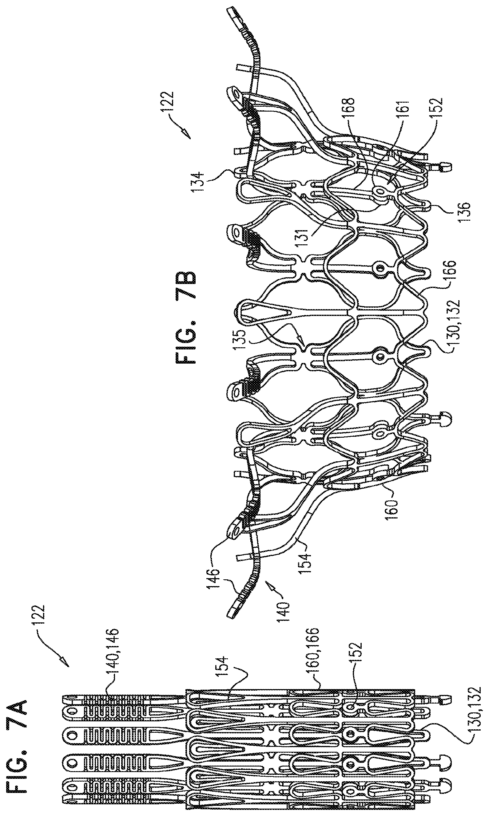
D00013
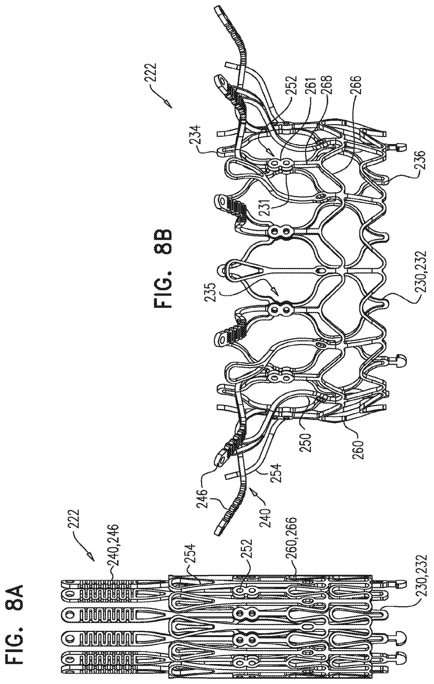
D00014
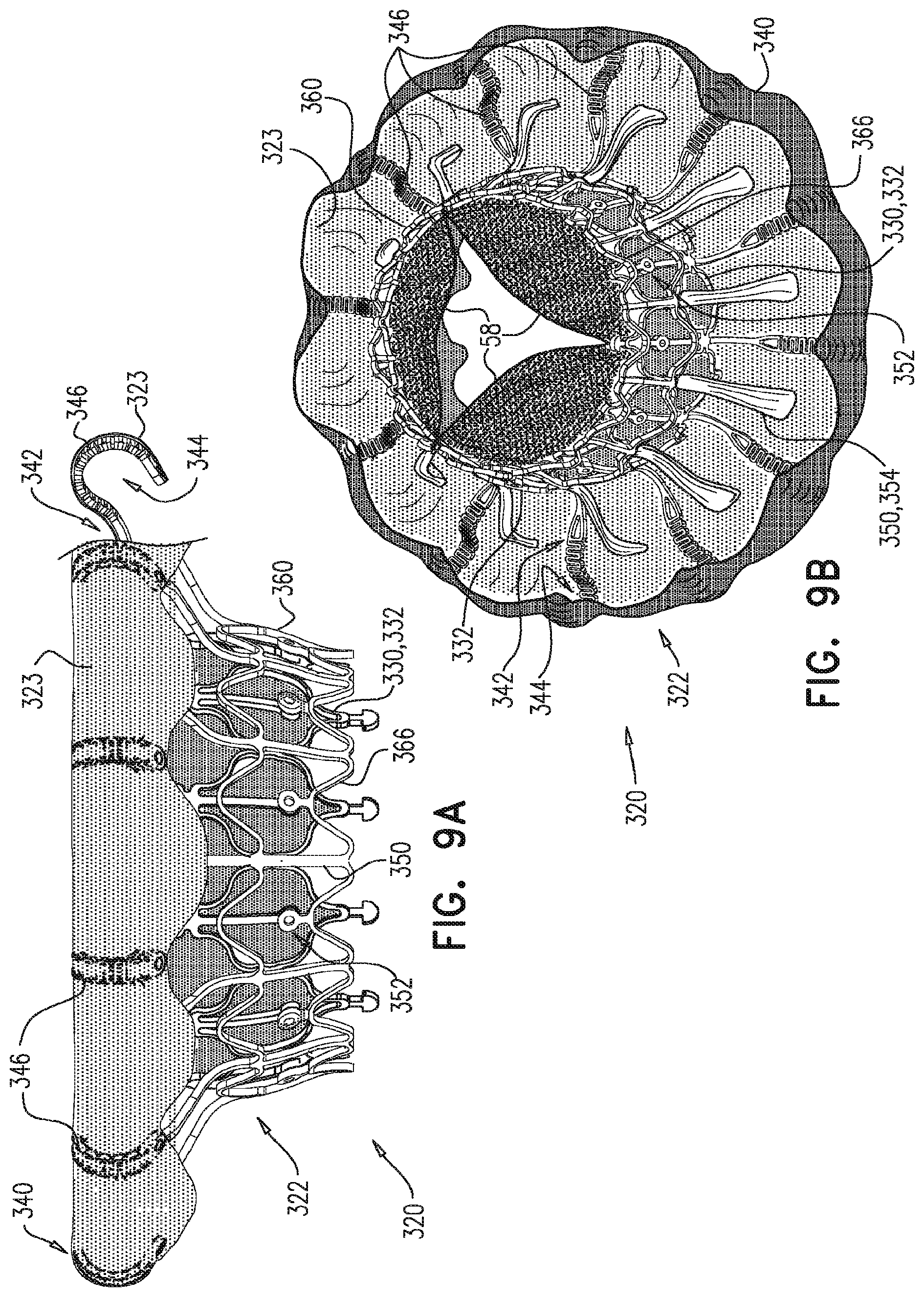
D00015
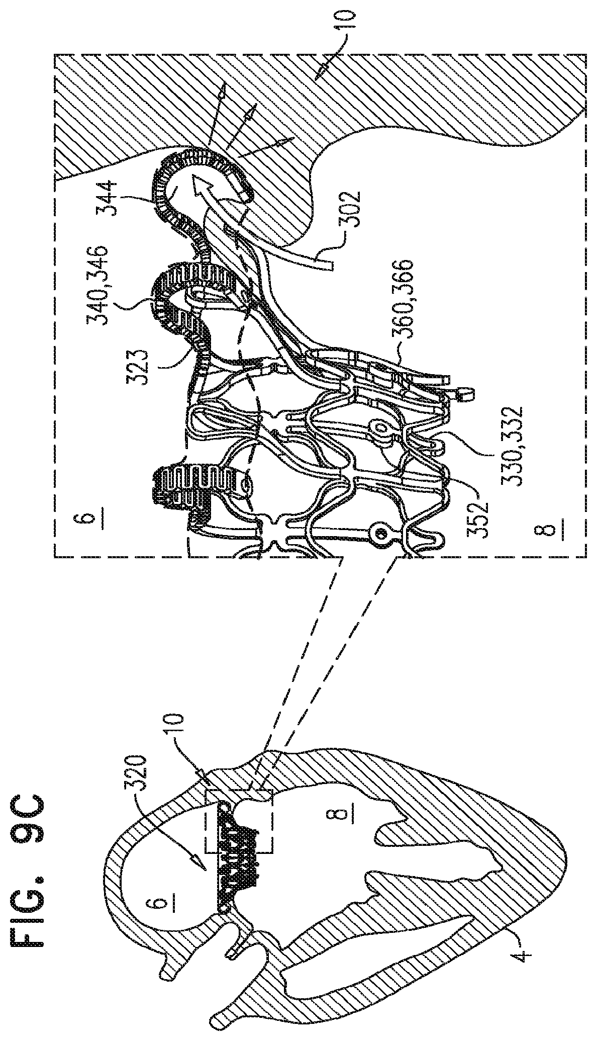
XML
uspto.report is an independent third-party trademark research tool that is not affiliated, endorsed, or sponsored by the United States Patent and Trademark Office (USPTO) or any other governmental organization. The information provided by uspto.report is based on publicly available data at the time of writing and is intended for informational purposes only.
While we strive to provide accurate and up-to-date information, we do not guarantee the accuracy, completeness, reliability, or suitability of the information displayed on this site. The use of this site is at your own risk. Any reliance you place on such information is therefore strictly at your own risk.
All official trademark data, including owner information, should be verified by visiting the official USPTO website at www.uspto.gov. This site is not intended to replace professional legal advice and should not be used as a substitute for consulting with a legal professional who is knowledgeable about trademark law.