Feedback Mechanisms For Handle Assemblies
Baril; Jacob C. ; et al.
U.S. patent application number 16/419123 was filed with the patent office on 2020-02-13 for feedback mechanisms for handle assemblies. The applicant listed for this patent is Covidien LP. Invention is credited to Ernest A. Addi, Jacob C. Baril, Brian J. Creston, Amy Kung, Matthew Malavenda, Christopher M. Meehan, Thomas A. Zammataro.
| Application Number | 20200046443 16/419123 |
| Document ID | / |
| Family ID | 67587663 |
| Filed Date | 2020-02-13 |


View All Diagrams
| United States Patent Application | 20200046443 |
| Kind Code | A1 |
| Baril; Jacob C. ; et al. | February 13, 2020 |
FEEDBACK MECHANISMS FOR HANDLE ASSEMBLIES
Abstract
A handle assembly for actuating an end effector includes a feedback mechanism for providing an audible and/or tactical response to indicate to the user that the handle assembly is fully actuated. The feedback mechanism may include a hammer member configured to strike a surface of the handle assembly to create the audible and/or tactical response.
| Inventors: | Baril; Jacob C.; (Norwalk, CT) ; Meehan; Christopher M.; (New Haven, CT) ; Creston; Brian J.; (West Haven, CT) ; Addi; Ernest A.; (Middletown, CT) ; Malavenda; Matthew; (West Haven, CT) ; Zammataro; Thomas A.; (Hamden, CT) ; Kung; Amy; (Milford, CT) | ||||||||||
| Applicant: |
|
||||||||||
|---|---|---|---|---|---|---|---|---|---|---|---|
| Family ID: | 67587663 | ||||||||||
| Appl. No.: | 16/419123 | ||||||||||
| Filed: | May 22, 2019 |
Related U.S. Patent Documents
| Application Number | Filing Date | Patent Number | ||
|---|---|---|---|---|
| 62717023 | Aug 10, 2018 | |||
| Current U.S. Class: | 1/1 |
| Current CPC Class: | A61B 17/00 20130101; A61B 17/00234 20130101; A61B 2017/2919 20130101; A61B 34/76 20160201; A61B 2017/00115 20130101; A61B 2017/0042 20130101; A61B 2090/0811 20160201; A61B 2017/0046 20130101; A61B 17/1285 20130101 |
| International Class: | A61B 34/00 20060101 A61B034/00; A61B 17/00 20060101 A61B017/00 |
Claims
1. A handle assembly, comprising: a housing defining a longitudinal axis; a trigger operably coupled to the housing and movable to cause actuation of the handle assembly; a drive member movable within the housing from an initial position to an advanced position in response to actuation of the trigger; and a feedback mechanism in operable engagement with the trigger, the feedback mechanism including a torsion spring having a hammer portion, wherein upon complete actuation of the handle assembly the hammer portion of the torsion spring strikes a surface to create at least one of an audible or a tactile response.
2. The handle assembly of claim 1, wherein the housing includes a body portion and a trigger portion.
3. The handle assembly of claim 2, wherein the feedback mechanism includes a ramp portion.
4. The handle assembly of claim 3, wherein the hammer portion of the torsion spring engages the ramp portion during actuation of the handle assembly to transition the torsion spring to a loaded condition.
5. The handle assembly of claim 4, wherein upon complete actuation of the handle assembly, the hammer portion of the torsion spring disengages the ramp portion to unload the torsion spring.
6. The handle assembly of claim 5, wherein upon unloading of the torsion spring, the hammer portion strikes the surface to create the at least one audible or tactile response.
7. The handle assembly of claim 1, wherein a first end of the torsion spring is secured relative to the trigger.
8. The handle assembly of claim 7, wherein the torsion spring includes a spring portion, the spring portion being received about a pivot pin secured to the trigger.
9. The handle assembly of claim 1, wherein an end of the torsion spring is secured to the housing.
10. The handle assembly of claim 9, wherein the torsion spring includes a spring portion, the spring portion being received about a pivot pin secured to the housing.
11. The handle assembly of claim 1, wherein the torsion spring is moved to a loaded condition during actuation of the handle assembly.
12. A handle assembly, comprising: a housing defining a longitudinal axis; a trigger operably coupled to the housing and movable to cause actuation of the handle assembly; a drive member movable within the housing from an initial position to an advanced position in response to actuation of the trigger, the drive member including a ramp portion; and a feedback mechanism including a hammer member in selective engagement with the ramp portion of the drive member, wherein upon complete actuation of the handle assembly, the hammer member disengages from the ramp portion and strikes a first pin to create at least one of an audible or a tactile response.
13. The handle assembly to claim 12, wherein movement of the drive member from the initial position to the advanced position causes the hammer member to move from a first position to a second position and back to the first position.
14. The handle assembly of claim 13, wherein return of the hammer member to the first position creates the at least one audible or tactile response.
15. The handle assembly of claim 13, wherein the feedback mechanism further includes a tension spring, the tension spring being secured to the hammer member and configured to bias the hammer member to the first position.
16. The handle assembly of claim 13, wherein return of the drive member to the initial position reengages the hammer member with the ramp portion.
17. A handle assembly, comprising: a housing defining a longitudinal axis; a trigger operably coupled to the housing and movable to cause actuation of the handle assembly; a drive member movable within the housing from an initial position to an advanced position in response to actuation of the trigger, the drive member including a ramp portion; and a feedback mechanism including first and second pins disposed within the housing, and a spring member secured to the drive member, wherein the spring member is configured to engage the first pin during the actuation of the handle assembly and disengage from the first pin upon complete actuation of the handle assembly.
18. The handle assembly of claim 17, wherein the spring member is configured to engage the second pin upon disengagement from first pin to create a least one of an audible or a tactile response.
19. The handle assembly of claim 17, wherein the spring member includes a torsion spring.
20. The handle assembly of claim 17, wherein the spring member transitions to a loaded condition during movement of the drive member from the initial position to the advanced position.
Description
CROSS-REFERENCE TO RELATED APPLICATION
[0001] This application claims the benefit of and priority to U.S. Provisional Patent Application No. 62/717,023 filed Aug. 10, 2018, the entire disclosure of which is incorporated by reference herein.
BACKGROUND
Technical Field
[0002] The present disclosure relates to handle assemblies for surgical instruments. More particularly, the present disclosure relates to mechanisms for providing feedback to a user to indicate full or complete actuation of the handle assembly.
Description of Related Art
[0003] Reusable handle assemblies are known in the art medical and are used for a number of distinct and useful surgical procedures. In the case of a laparoscopic surgical procedure, access to the interior of an abdomen is achieved through narrow tubes or cannulas that are releasably secured to the reusable handles inserted through a small entrance incision in the skin. Minimally invasive procedures performed elsewhere in the body are often generally referred to as endoscopic procedures.
[0004] During, for example, a surgical procedure using a clip applier, clip formation occurs upon completion of a firing stroke. To ensure clip formation, it would be beneficial to have a handle assembly with an audible and/or tactile feedback mechanism to signal to a user when the actuation stroke is complete.
SUMMARY
[0005] A handle assembly for actuating an end effector is provided. The handle assembly includes a housing defining a longitudinal axis, a trigger operably coupled to the housing and movable to cause actuation of the handle assembly, a drive member movable within the housing from an initial position to an advanced position in response to actuation of the trigger, and a feedback mechanism in operable engagement with the trigger. The feedback mechanism includes a torsion spring having a hammer portion. Upon full actuation of the handle assembly, the hammer portion of the torsion spring strikes a surface to create at least one of an audible or a tactile response.
[0006] In embodiments, the housing includes a body portion and a trigger portion. The feedback mechanism may include a ramp portion. The hammer portion of the torsion spring may engage the ramp portion during actuation of the handle assembly to transition the torsion spring to a loaded condition. Upon complete actuation of the handle assembly, the hammer portion of the torsion spring may disengage the ramp portion to unload the torsion spring. Upon unloading of the torsion spring, the hammer portion may strike the surface to create the at least one audible or tactile response.
[0007] A first end of the torsion spring may be secured relative to the trigger. When secured relative to the trigger, the torsion spring may include a spring portion which may be received about a pivot pin secured to the trigger. An end of the torsion spring may be secured to the housing. When secured to the housing, the torsion spring may include a spring portion which may be received about a pivot pin secured to the housing. The torsion spring may be moved to a loaded condition during actuation of the handle assembly.
[0008] Another handle assembly for actuating an end effector is provided. The handle assembly includes a housing defining a longitudinal axis, a trigger operably coupled to the housing and movable to cause actuation of the handle assembly, and a drive member movable within the housing from an initial position to an advanced position in response to actuation of the trigger. The drive member includes a ramp portion. The handle assembly further includes a feedback mechanism including a hammer member in selective engagement with the ramp portion of the drive member. Upon complete actuation of the handle assembly, the hammer member disengages from the ramp portion and strikes a first pin to create at least one of an audible or a tactile response.
[0009] Movement of the drive member from the initial position to the advanced position may cause the hammer member to move from a first position to a second position and back to the first position. Return of the hammer member to the first position may create the at least one audible or tactile response. The feedback mechanism further includes a tension spring, the tension spring being secured to the hammer member and configured to bias the hammer member to the first position. Return of the drive member to the initial position may reengage the hammer member with the ramp portion.
[0010] Another handle assembly for actuating an end effector is provided. The handle assembly includes a housing defining a longitudinal axis, a trigger operably coupled to the housing and movable to cause actuation of the handle assembly, and a drive member movable within the housing from an initial position to an advanced position in response to actuation of the trigger. The drive member includes a ramp portion. The handle assembly further includes a feedback mechanism having first and second pins disposed within the housing, and a spring member secured to the drive member. The spring member is configured to engage the first pin during the actuation of the handle assembly and disengage from the first pin upon full actuation of the handle assembly.
[0011] In embodiments, the spring member is configured to engage the second pin upon disengagement from first pin to create a least one of an audible or tactile response. The spring member may include a torsion spring. The spring member may transition to a loaded condition during movement of the drive member from the initial position to the advanced position.
BRIEF DESCRIPTION OF THE DRAWINGS
[0012] Aspects and features of the present disclosure are described in detail with reference to the drawing figures wherein like reference numerals identify similar or identical structural elements and:
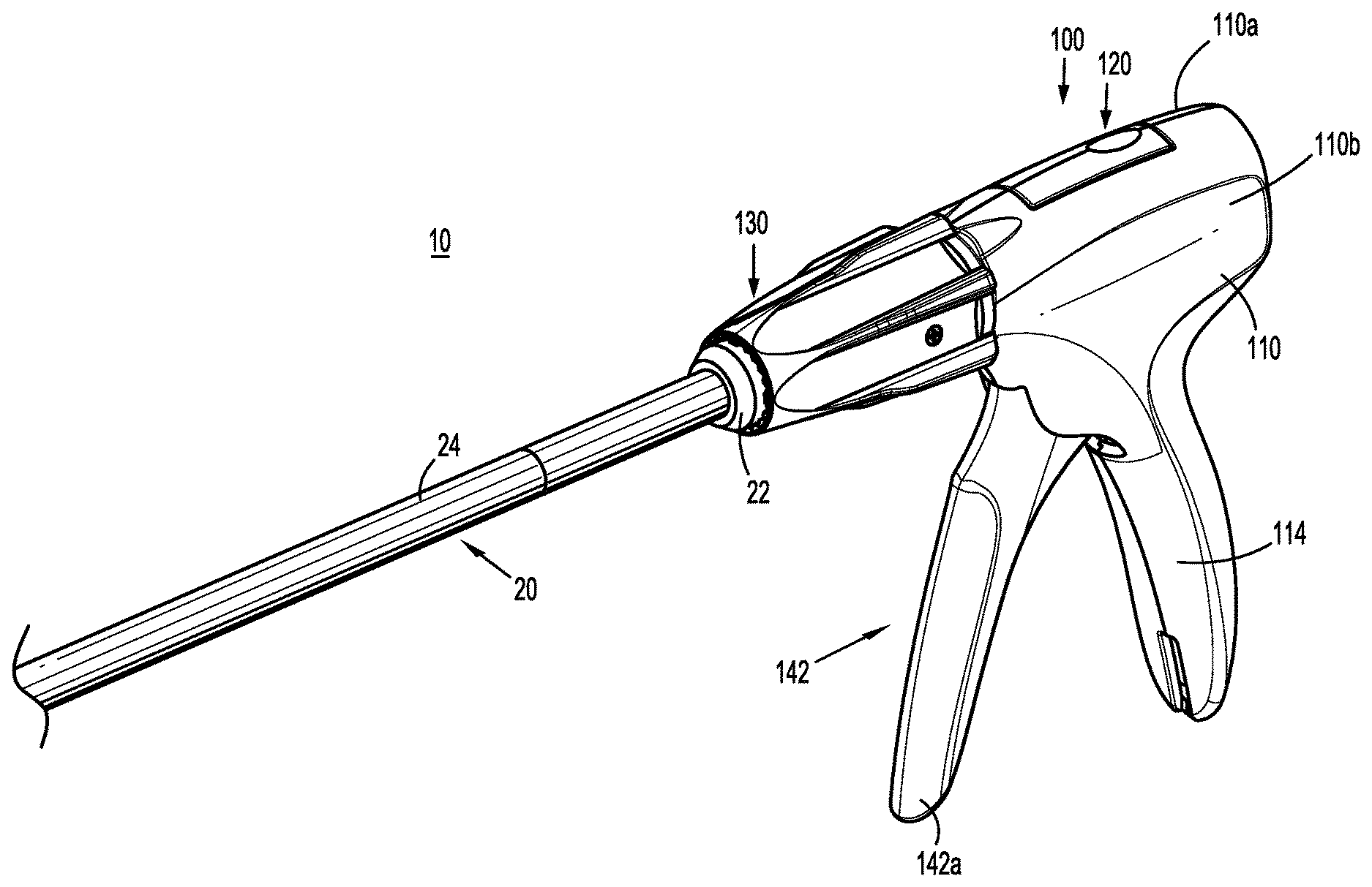
[0013] FIG. 1 is a front, perspective view of a surgical clip applier according to an embodiment of the present disclosure including a handle assembly having an elongated assembly engaged therewith;
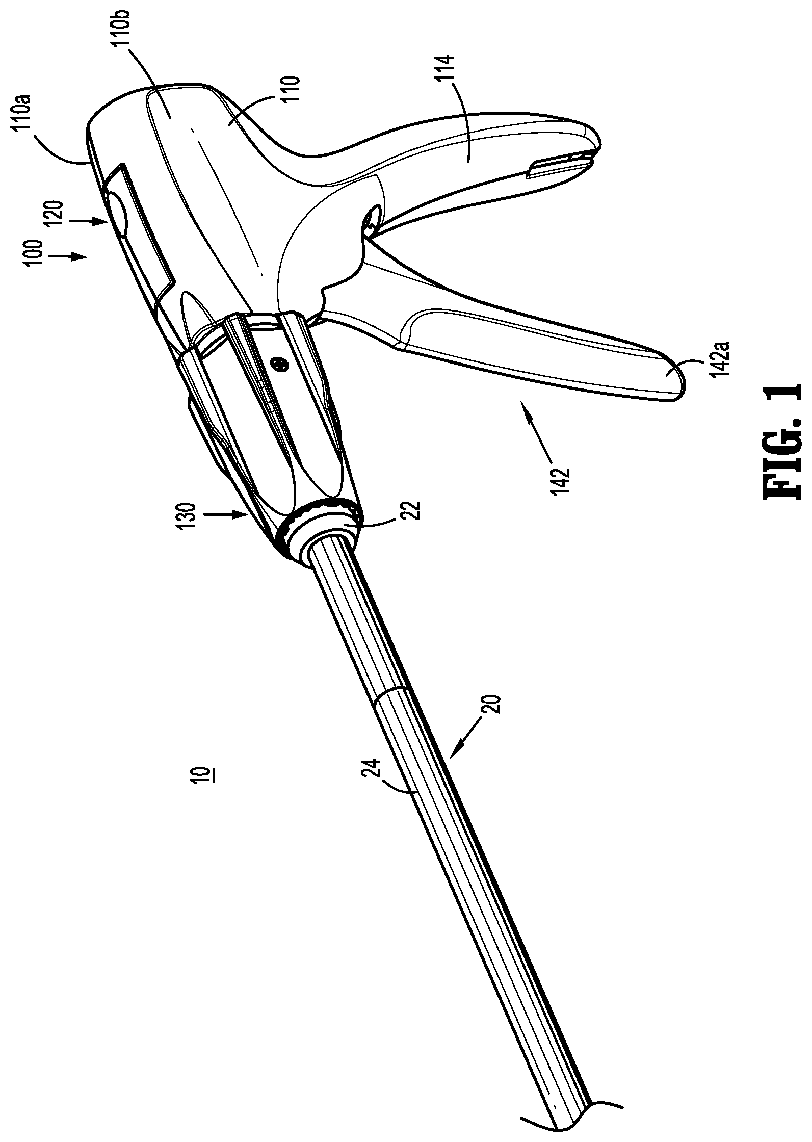
[0014] FIG. 2 is front, perspective view of the surgical clip applier with the elongated assembly removed from the handle assembly;
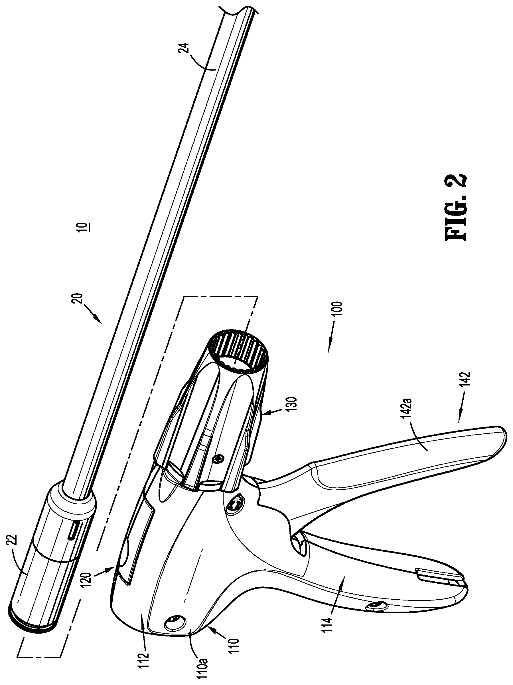
[0015] FIG. 3 is a side perspective view of the handle assembly of the surgical clip applier shown in FIGS. 1 and 2, with a housing half removed exposing an actuation assembly including a trigger and a feedback mechanism;
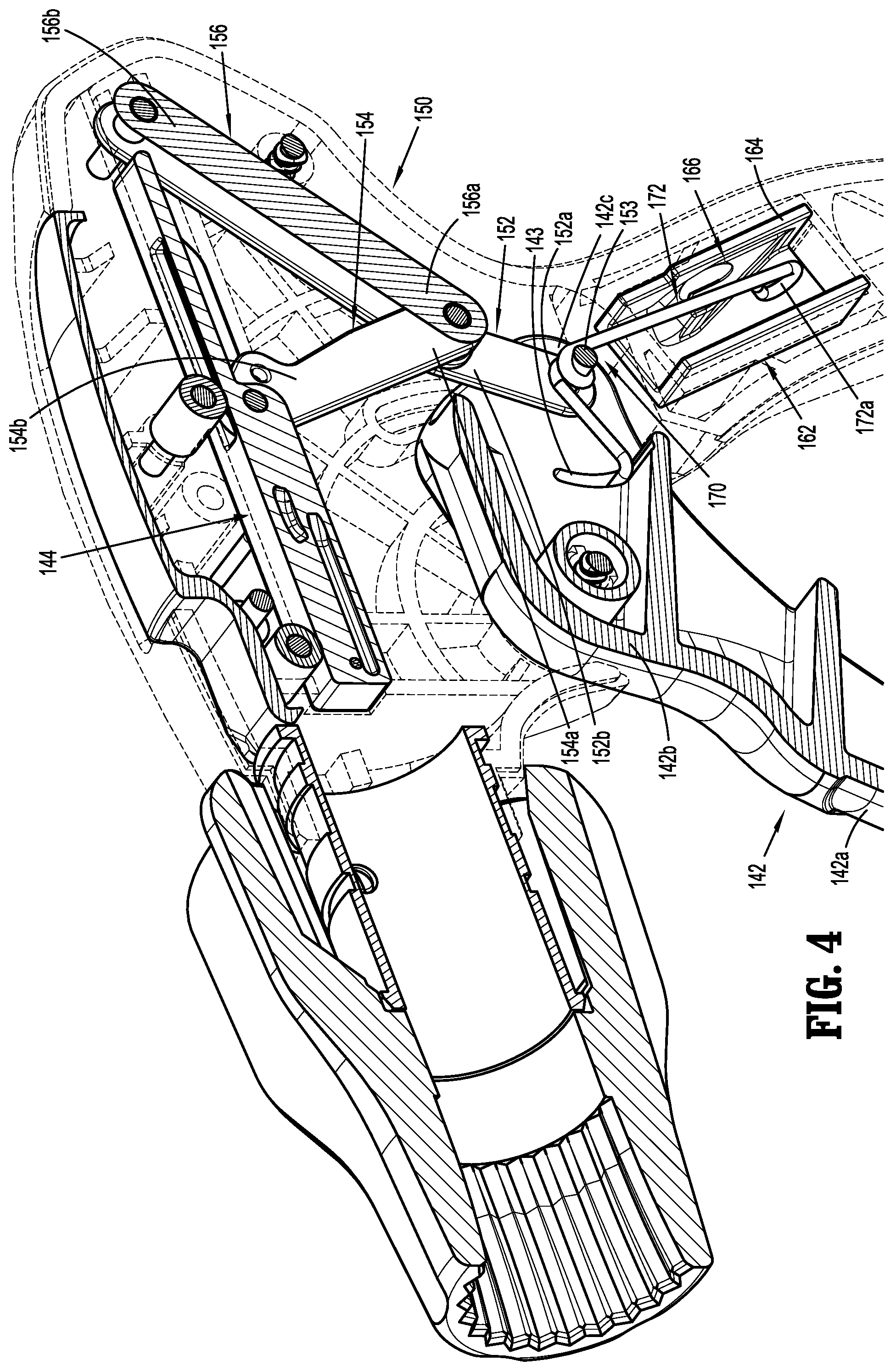
[0016] FIG. 4 is a cross-sectional perspective view taken along line 4-4 shown in FIG. 3;
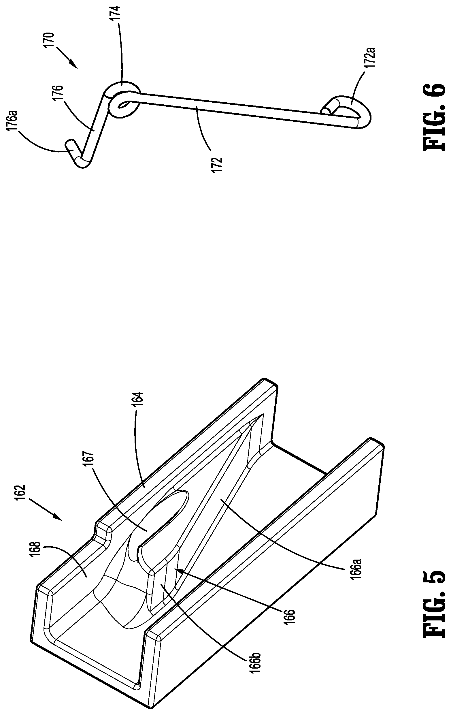
[0017] FIG. 5 is a side perspective view of a base member of the feedback mechanism shown in FIG. 3;
[0018] FIG. 6 is a side perspective view of a torsion spring of the feedback mechanism shown in FIG. 3;
[0019] FIG. 7 is a cross-sectional side view taken along line 4-4 shown in FIG. 3, with a trigger in a first or initial position;
[0020] FIG. 8 is a cross-sectional side view taken along line 4-4 shown in FIG. 3 of the handle assembly shown in FIG. 3 with the trigger in a partially actuated position;
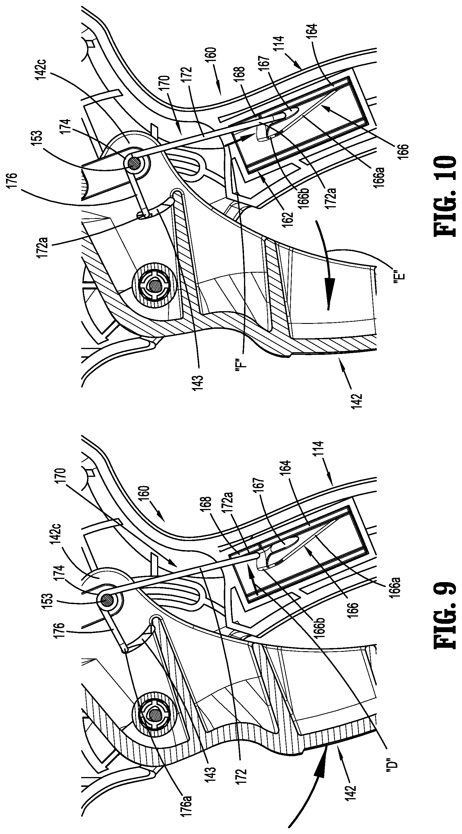
[0021] FIG. 9 is a cross-sectional side view taken along line 4-4 shown in FIG. 3 of the handle assembly shown in FIG. 3 with the trigger in a fully actuated position;
[0022] FIG. 10 is a cross-sectional perspective view taken along line 4-4 shown in FIG. 3 of the handle assembly shown in FIG. 3 with the trigger in a partially returned position;
[0023] FIG. 11 is a perspective end view of a handle assembly including a feedback mechanism according to another embodiment of the present disclosure;
[0024] FIG. 12 is an enlarged view of the indicated area of detail shown in FIG. 11;
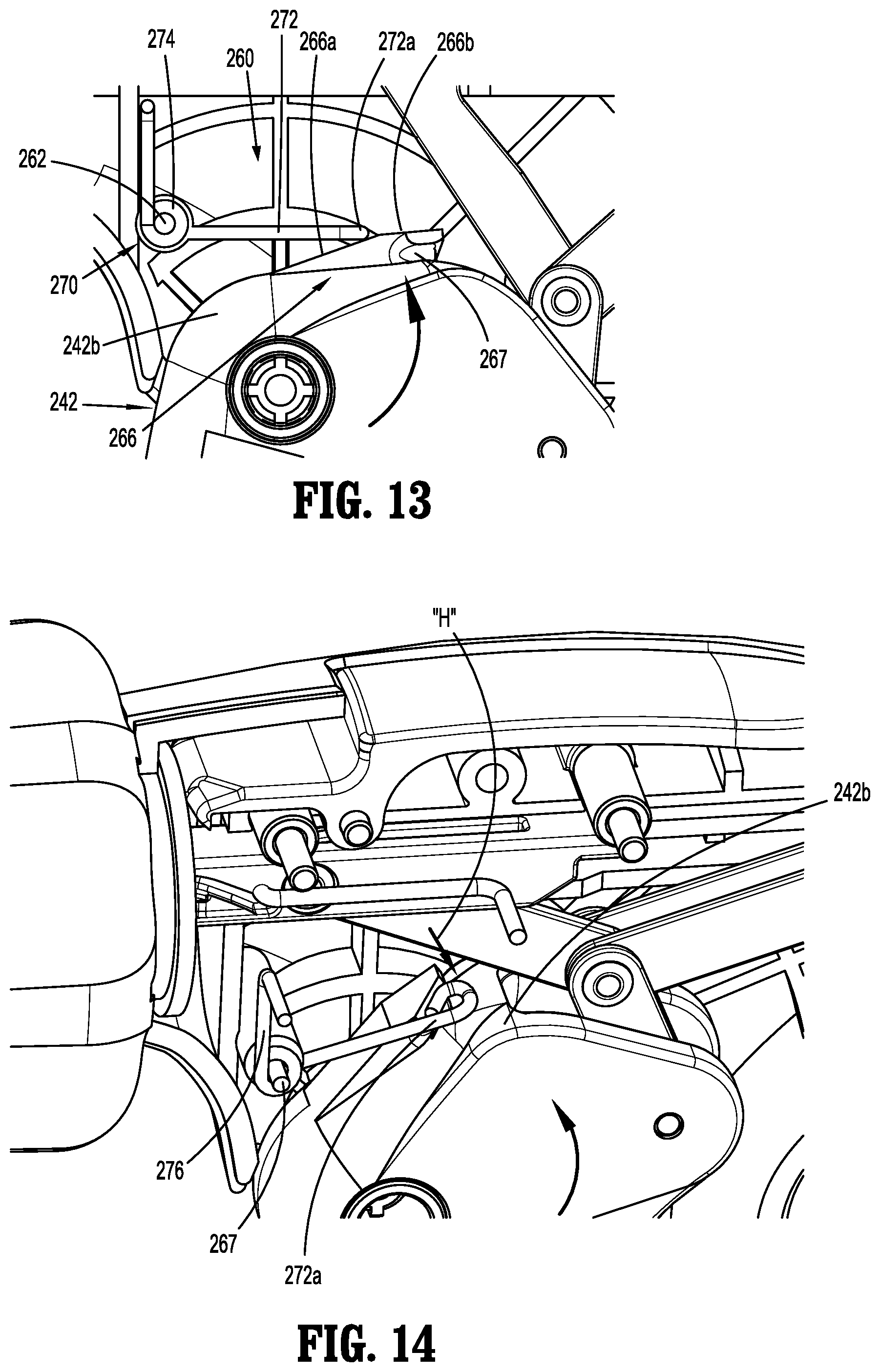
[0025] FIG. 13 is an enlarged side view of the feedback mechanism shown in FIG. 11 with a trigger in a partially actuated position;
[0026] FIG. 14 is a side perspective view of the feedback mechanism shown in FIG. 11 with the trigger in a fully actuated position;
[0027] FIG. 15 is an enlarged side perspective view of the feedback mechanism shown in FIG. 11 with the trigger in a partially returned position;
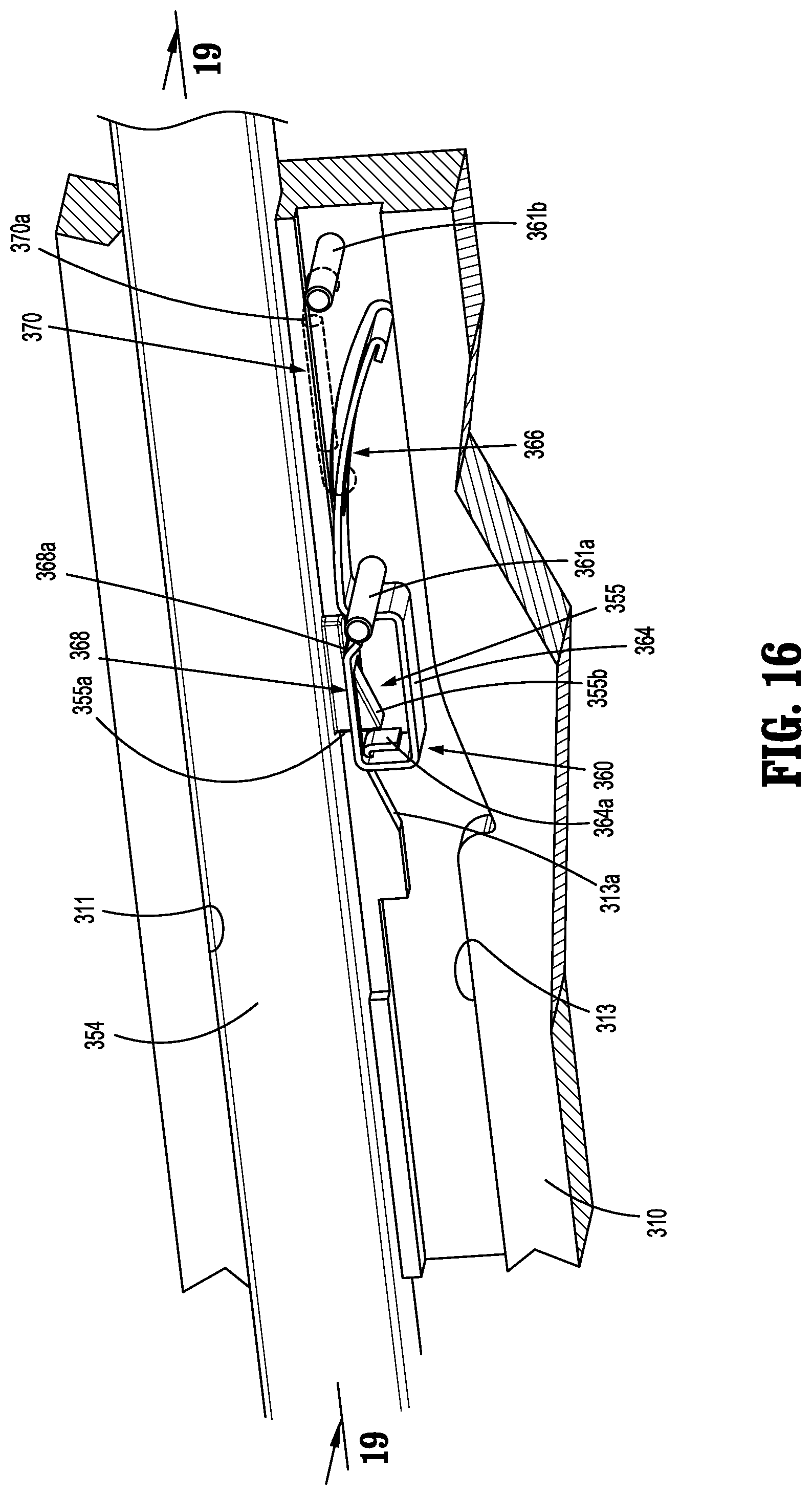
[0028] FIG. 16 is a side perspective view of a feedback mechanism according to another embodiment of the present disclosure;
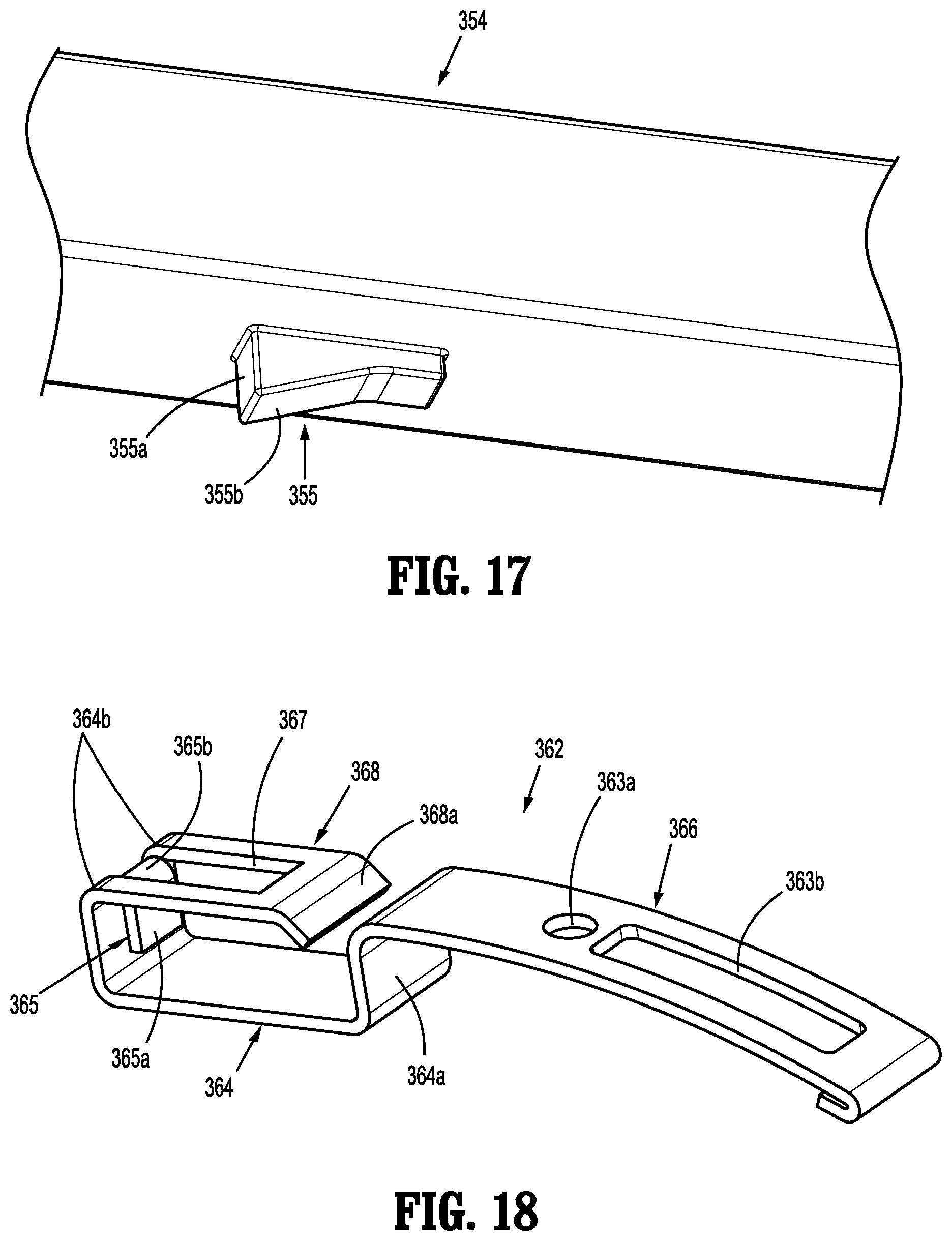
[0029] FIG. 17 is a side perspective view of a hammer member of the feedback mechanism shown in FIG. 16;
[0030] FIG. 18 is an enlarged side perspective view of a ramp of the feedback mechanism shown in FIG. 16 extending from a drive bar;
[0031] FIG. 19 is a cross-sectional side view taken along line 19-19 shown in FIG. 16, with the drive bar in a first or fully retracted position;
[0032] FIG. 20 is a cross-sectional side view taken along line 19-19 shown in FIG. 16, with the drive bar in a partially advanced position;
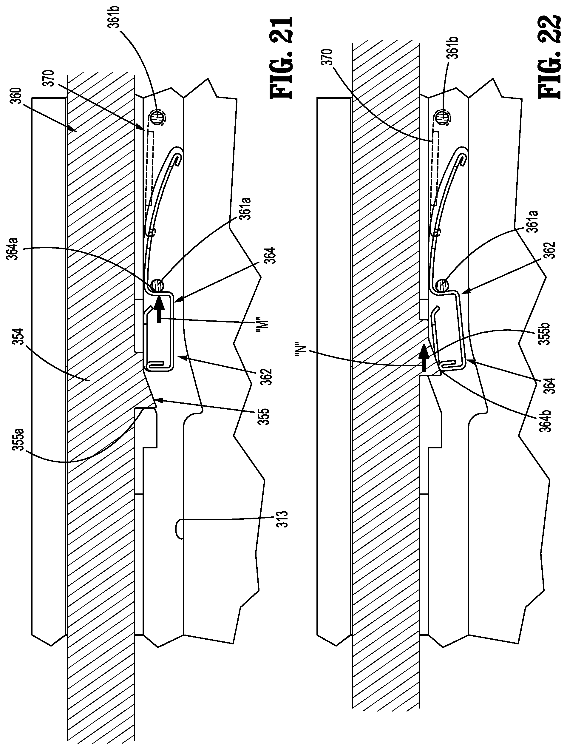
[0033] FIG. 21 is a cross-sectional side view taken along line 19-19 shown in FIG. 16, with the drive bar in a fully advanced position;
[0034] FIG. 22 is a cross-sectional side view taken along line 19-19 shown in FIG. 16, with the drive bar in a partially retracted position;
[0035] FIG. 23 is a perspective view of a feedback mechanism according to yet another embodiment of the present disclosure;
[0036] FIG. 24 is a perspective view of a spring member of the feedback mechanism shown in FIG. 23;
[0037] FIG. 25 is a side view of the feedback mechanism shown in FIG. 23 with a drive bar in a first or fully retracted position;
[0038] FIG. 26 is a side view of the feedback mechanism shown in FIG. 23 with the drive bar in a partially advanced position;
[0039] FIG. 27 is a side view of the feedback mechanism shown in FIG. 23 with the drive bar in a fully advanced position; and
[0040] FIG. 28 is a perspective view of a feedback mechanism according to still another embodiment of the present disclosure.
DETAILED DESCRIPTION
[0041] As detailed herein and shown in the drawing figures, as is traditional when referring to relative positioning on a surgical instrument, the term "proximal" refers to the end of the apparatus or component thereof which is closer to the user and the term "distal" refers to the end of the apparatus or component thereof which is farther away from the user. Further, to the extent consistent, any or all of the aspects and features detailed herein may be used in conjunction with any or all of the other aspects and features detailed herein.
[0042] The present disclosure provides feedback mechanisms for handle assemblies of surgical instruments. Although detailed herein as incorporated into handle assemblies for surgical clip appliers, the feedback mechanism of the present disclosure may be incorporated into any suitable surgical instrument.
[0043] Turning to FIGS. 1 and 2, a surgical clip applier according to aspects of the present disclosure is shown generally as clip applier 10. The clip applier 10 generally includes a handle assembly 100 and an adapter assembly 20 selectively connectable to the handle assembly 100. The handle assembly 100 is configured to operate the adapter assembly 20 upon connection of the adapter assembly 20 to the handle assembly 100, and may be configured as a sterilizable, reusable component such that handle assembly 100 may be repeatedly used with different and/or additional elongated assemblies (not shown) during the course of one or more surgical procedures. The adapter assembly 20 may be configured as a single-use disposable component, limited-use disposable components, or reusable components, depending upon a particular purpose and/or the configuration of the particular adapter assembly. In either configuration, the need for multiple handle assemblies 100 is obviated and, instead, the surgeon need only select an appropriate adapter assembly, and connect that adapter assembly to the handle assembly 100 in preparation for use.
[0044] The handle assembly 100 includes a housing 110, a latch assembly 120 (FIG. 3) operably disposed within housing 110, a rotation knob assembly 130 disposed on a distal end of the housing 110, and an actuation mechanism 140 operably disposed within the housing 110. The housing 110 supports and/or encloses the operating components of handle assembly 100. The latch mechanism 120 is configured to facilitate releasable locking engagement of the adapter assembly 20 with the handle assembly 100. The rotation knob assembly 130 enables the selective rotation of the attached adapter assembly 20 relative to the housing 110. The actuation mechanism 140 is configured to enable selective firing of one or more surgical clips (not shown) from an end effector (not shown) of the attached adapter assembly 20.
[0045] The handle assembly 100 will only be described to the extent necessary to fully disclose the aspects of the present disclosure. For a detailed description of the operation and function of an exemplary handle assembly, including exemplary latch and rotation knob assemblies, please refer to commonly owned U.S. Prov. Pat. App. Ser. No. 62/581,144, filed Nov. 3, 2017, the content of which is incorporated herein by reference in its entirety. Other exemplary embodiments of handle assemblies may be found in commonly owned Intl. Pat. App. Nos. PCT/CN2016/096666 and PCT/CN2016/071178, filed on Aug. 26, 2016 and Jan. 18, 2016, respectively, the content of each is hereby incorporated herein by reference in its entirety.
[0046] Referring still to FIGS. 1 and 2, the adapter assembly 20 of the clip applier 10 generally includes a proximal hub 22, an elongated shaft 24 extending distally from the proximal hub 22, an end effector (not shown) disposed towards a distal end portion of the elongated shaft 24, and an inner drive assembly (not shown) operably coupled between the handle assembly 100 and the end effector when adapter assembly 20 is engaged with the handle assembly 100, to enable the sequential firing of at least one surgical clip (not shown) about tissue. The end effector of the adapter assembly 20 may be configured to fire surgical clips similar to those shown and described in U.S. Pat. No. 7,819,886 or 7,905,890, the content of each of which is hereby incorporated herein by reference in its entirety.
[0047] With additional reference to FIG. 3, the housing 110 of the handle assembly 100 may be formed from first and second housing halves 110a, 110b (FIG. 1) that cooperate to define a body portion 112, and a fixed handle portion 114 depending from the body portion 112. A proximal end portion of the proximal hub 22 of the adapter assembly 20 is configured to extend at least partially through an opening in a distal nose 112a of the housing 110 when the adapter assembly 20 (FIG. 1) is engaged with the handle assembly 100. The body portion 112 of housing 110 further includes an internal pivot post 116 extending transversely within body portion 112.
[0048] The actuation mechanism 140 of the handle assembly 100 is operably supported by the housing 110 and includes a trigger member 142, a drive bar 144 operably connected to the trigger member 142 by a linkage assembly 150, and a feedback mechanism 160 operably connected to the trigger member 142. As described below, the feedback mechanism 160 produces an audible and/or or tactile response during actuation of the handle assembly 100 to indicate completion of a firing or actuation stroke of the handle assembly 100.
[0049] The trigger member 142 of the actuation mechanism 140 includes a grasping portion 142a, an intermediate pivot portion 142b, and a proximal extension 142c. The grasping portion 142a of the trigger member 142 extends downwardly from the body portion 112 of the housing 110 in opposed relation relative to the fixed handle portion 114 of the housing 110. The grasping portion 142a is configured to facilitate grasping and manipulation of the trigger member 142.
[0050] The intermediate pivot portion 142b of the trigger member 142 is at least partially disposed within the housing 110 and defines a pivot aperture 151 that is configured to receive the pivot post 116 of the housing 110 so as to enable pivoting of the trigger member 142 about the pivot post 116 and relative to the housing 110, e.g., between an initial or pre-actuated position (FIG. 3), wherein the grasping portion 142a of the trigger member 142 is spaced-apart from the fixed handle portion 114, and a fully actuated position (FIG. 9), wherein the grasping portion 142a of the trigger member 142 is approximated relative to the fixed handle portion 114.
[0051] The proximal extension 142c of the trigger member 142 is disposed on an opposite side of the intermediate pivot portion 142b and, thus, opposite the pivot post 116, as compared to the grasping portion 142a of the trigger member 142. As such, pivoting of the grasping portion 142a to rotate in one direction, e.g., proximally towards the fixed handle portion 114, pivots the proximal extension 142c to rotate in the opposite direction, e.g., distally. As described in detail below, the proximal extension 142c of the trigger member 142 defines an arcuate slot 143 for receiving an engagement portion 176 of a torsion spring 170 of the feedback mechanism 160.
[0052] The linkage assembly 150 of the actuation assembly 140 includes a first linkage member 152, a second linkage member 154, and a third linkage member 156. A first portion 152a of the first linkage member 152 is pivotally coupled to the proximal extension 142c of the trigger member 142 by a pivot pin 153. The second and third linkages 154, 156, respectively, are each pivotally coupled to a second portion 152b of the first linkage member 152 at respective first portions 154a, 156a of the respective second and third linkages 154, 156. A second portion 154b of the second linkage member 154 is pivotally coupled to the drive bar 144, while a second portion 156b of the third linkage member 156 is pivotally coupled to the body portion 112 of the housing 110. Thus, the pivot point between the first linkage member 152 and the proximal extension 142c of the trigger member 142, the pivot point between the first linkage member 152 and second and third linkages 154, 156, respectively, and the pivot point between the second linkage member 154 and the drive bar 144 are movable pivot points (e.g., movable relative to the housing 110), while the pivot point between the third linkage member 156 and the housing 110 is a fixed pivot point (e.g., fixed relative to the housing 110).
[0053] The feedback mechanism 160 of the handle assembly 100 includes a base member 162 and a torsion spring 170. The base member 162 is disposed within the fixed trigger portion 114 of the housing 110 and the torsion spring 170 is operably received about the pivot pin 153 that secures the first linkage 152 to the proximal extension 142c of the trigger member 142. In embodiments, the base member 162 operates in conjunction with the torsion spring 170 to produce an audible sound and/or tactile response/feedback when the trigger member 142 completes a firing stroke.
[0054] With particular reference to FIG. 5, the base member 162 of the feedback mechanism 160 includes a substantially U-shaped body 164 supported within the fixed trigger portion 114 of the housing 110. A ramp portion 166 is disposed within the U-shaped body 164 of the base member 162. The ramp portion 166 includes an inclined surface 166a and an edge surface 166b. The base member 162 includes a sounding surface 168 disposed adjacent the edge surface 166b of the ramp portion 166. As will be described below, a hammer portion 172a of the torsion spring 170 rides along the inclined surface 166a of the ramp portion 166 during actuation of the handle assembly 100, and slides off of the edge surface 166b of the ramp portion 166 and into engagement with the sounding surface 168 upon completion of the firing stroke. The ramp portion 166 of the base member 162 defines a cam track 167 for repositioning the hammer portion 172 of the torsion spring following actuation of the handle assembly 100.
[0055] The base member 162 may be formed of metal or plastic. In embodiments, the base member 162 is formed by metal injected molding (MIM).
[0056] Turning now to FIG. 6, the torsion spring 170 of the feedback mechanism includes an elongate body 172 having the hammer portion 172a on a first, free end and a spring portion 174 on a second end. A flange portion 176 extends from the spring portion 174 and includes an engagement portion 176a formed on a free end of the flange portion 176.
[0057] With additional reference to FIGS. 7-9, the spring portion 174 of the torsion spring 170 of the feedback mechanism 160 is received about the pivot pin 153 that secures the first linkage 152 of the linkage assembly 150 to the proximal extension 142c of the trigger member 142. The elongate portion 172 of the torsion spring 170 is operably received within the base member 162 of the feedback mechanism 160 and the engagement portion 176a of the torsion spring 170 is received within the arcuate slot 143 in the proximal extension 142c of the trigger member 142.
[0058] With particular reference to FIG. 8, upon actuation of the trigger member 142, e.g., proximal pivoting of the grasping portion 142a of the trigger member 142 toward the fixed handle portion 114 of the housing 110, as indicated by arrow "A", the proximal extension 142c is moved in a counter-clockwise direction. The counter-clockwise movement of the proximal extension 142c of the trigger member 142 effects movement of the hammer portion 172 on the free end of the elongate body 172 of the torsion spring 170 along the inclined surface 166a of the ramp portion 166 of the base member 162, as indicated by arrow "B". During actuation of the trigger member 142, the engagement portion 176a on the free end of the flange portion 176 of the torsion spring 170 rides along the slot 143 in the proximal extension 142c of the trigger member 142, as indicated by arrow "C", and flexes to cam the spring portion 174 of the torsion spring 170 to a loaded condition.
[0059] Turning to FIG. 9, the ramp portion 166 of the base member 162 and the torsion spring 170 of the feedback mechanism 160 are configured such that at the end of the actuation stroke, the hammer portion 172a of the torsion spring 170 disengages from the edge surface 166b of the ramp portion 166. As noted above, during actuation of the trigger member 142, the spring portion 174 is cammed to the loaded condition. In this manner, when the hammer portion 172a of the torsion spring 170 disengages from the edge surface 166b of the ramp portion 166, the hammer portion 172a snaps against the sounding surface 168 of the base member 162, as indicated by arrow "D", thereby producing an audible sound. It is envisioned that the contact of the hammer portion 172a of the torsion spring 170 with the sounding surface 168 may also produce a tactile response, e.g. vibration.
[0060] With reference to FIG. 10, as the trigger member 142 returns to its initial position, as indicated by arrow "E", the elongate body 172 of the torsion spring 170 advances within the base member 162, as indicated by arrow "F", such that the hammer portion 172a of the torsion spring engages the cam track 167 of the ramp portion 166. As the hammer portion 172a engages the cam track 167 of the ramp portion 166, the hammer portion 172a is guided past the ramp portion 166 to return to its initial position disposed along the inclined surface 166a of the ramp portion 166, thereby resetting the feedback mechanism 160, and readying the handle assembly 100 for further use.
[0061] With reference now to FIGS. 11-15, a reusable handle assembly including a feedback mechanism according to another embodiment of the present disclosure is shown generally as handle assembly 200. The handle assembly 200 is substantially similar to the handle assembly 100 described hereinabove and will only be described in detail as relates to the differences therebetween.
[0062] The handle assembly 200 includes a housing 210, a latch assembly 220 operably disposed within the housing 210, a rotation knob assembly 230 dispose on a distal nose 212a of a body portion 212 of the housing 210, and an actuation mechanism 240 operably supported within the housing 210. First and second housing halves 210a (only one shown) of the housing 210 cooperate to define the body portion 212 and a fixed handle portion 214 depending from the body portion 212. The body portion 212 of housing 210 includes an internal pivot post 216 extending transversely within body portion 212.
[0063] The actuation mechanism 240 of the handle assembly 200 includes a trigger member 242, a drive bar 244 operably connected to the trigger member 242 by a linkage assembly 250, and a feedback mechanism 260 operably connected to the trigger member 242 to signal completion of a firing stroke. As described below, the feedback mechanism 250 produces an audible and/or or tactile feedback during actuation of the handle assembly 200 upon completion of an actuation stroke, e.g., full clip formation.
[0064] The trigger member 242 of the actuation mechanism 240 includes a grasping portion 242a, an intermediate pivot portion 242b, and a proximal extension 242c. The intermediate pivot portion 242b of the trigger member 242 is at least partially disposed within the housing 210 and defines a pivot aperture 251 that is configured to receive the pivot post 216 of the housing 210. The trigger member 242 pivots about the pivot post 216 and relative to the housing 210, e.g., between an initial or pre-actuated position (FIG. 11), wherein the grasping portion 242a of the trigger member 242 is spaced-apart relative to the fixed handle portion 214, and an actuated position (FIG. 14), wherein the grasping portion 242a of the trigger member 242 is approximated relative to the fixed handle portion 214.
[0065] The feedback mechanism 260 is operably disposed within the body portion 212 of the housing 210 of the handle assembly 200 and includes a ramp portion 266 and a torsion spring 270. More particularly, the ramp portion 266 is formed on an outer surface of the intermediate pivot portion 242b of the trigger member 242 of the actuation assembly 240. The ramp portion 266 includes an inclined surface 266a and an edge surface 266b, and defines a cam track 267. As will be detailed below, during a firing stroke of the handle assembly 200, the ramp portion 266 directs a hammer portion 272a of the torsion spring 270 into a snapping engagement with an outer surface of the intermediate pivot portion 242b of the trigger member 242 to provide an audible and/or tactile response that the handle assembly 200 firing stroke is complete, e.g., the actuation assembly 240 is fully actuated. The ramp portion 266 is configured to reset the hammer portion 272a of the torsion spring 270 as the trigger member 242 returns to its pre-actuated position to permit subsequent firing of the handle assembly 200.
[0066] The torsion spring 270 includes an elongate body 272 with the hammer portion 272a disposed on a first, free end and a spring portion 274 on a second end. A flange portion 276 extends from the spring portion 274 and includes an engagement portion 276a formed on a free end of the flange portion 276.
[0067] The spring portion 274 of the torsion spring 270 of the feedback mechanism 260 is received by a pivot pin 262 that is supported within the body portion 212 of the housing 210. The elongate portion 272 of the torsion spring 270 extends towards the intermediate pivot portion 242b of the trigger member 242 such that the hammer portion 272a of the torsion spring 270 engages the inclined portion 266a of the ramp portion 266 of the feedback mechanism 260. The engagement portion 276a of the torsion spring 270 engages the body portion 112 of the housing 210 and remains in a fixed position.
[0068] With particular reference to FIG. 13, upon actuation of the trigger member 242, e.g., proximal pivoting of the grasping portion 242a of the trigger member 242 toward the fixed handle portion 214 of the housing 210, the intermediate pivot portion 242b of the trigger member 242 moves in a counter-clockwise direction, as indicated by arrow "G". The counter-clockwise movement of the intermediate pivot portion 242b of the trigger member 242 causes the hammer portion 272a on the free end of the elongate body 272 of the torsion spring 270 to ride along the inclined surface 266a of the ramp portion 266 of the feedback mechanism 260. During actuation of the trigger member 242, the engagement portion 276a on the free end of the flange portion 276 of the torsion spring 270 remains in a fixed position. The movement of the hammer portion 272a of the torsion spring 270 along the inclined surface 266a of the ramp portion 266 cams the spring portion 274 of the torsion spring 270 to a loaded condition.
[0069] Turning to FIG. 14, the ramp portion 266 and the torsion spring 270 of the feedback mechanism 260 are configured such that at the end of the actuation stroke, the hammer portion 272a of the torsion spring 270 disengages from the edge surface 266b of the ramp portion 266. As noted above, during actuation of the trigger member 242, the spring portion 274 is cammed to the loaded condition. In this manner, when the hammer portion 272a of the torsion spring 270 disengages from the edge surface 266b of the ramp 262, the hammer portion 272a snaps against the outer surface of the intermediate pivot portion 242b of the trigger member 242, as indicated by arrow "H", thereby producing an audible response. It is envisioned that the contact of the hammer portion 272a of the torsion spring 270 may also produce a tactile response, e.g., vibration.
[0070] With reference to FIG. 15, as the trigger member 242 returns to its initial position, as indicated by arrow "I", the elongate body 272 of the torsion spring 270 advances relative to the ramp portion 266 such that the hammer portion 272a of the torsion spring 270 engages the cam track 267 of the ramp portion 266. As the hammer portion 272a engages the cam track 267 of the ramp portion 266, the hammer portion 272a is guided around the ramp portion 266, as indicated by arrow "J", to return to its initial position disposed along the inclined surface 266a of the ramp portion 266, thereby resetting the feedback mechanism 260, and readying the handle assembly 200 for further use.
[0071] With reference now to FIGS. 16-22, a feedback mechanism according to another embodiment of the present disclosure is shown generally as feedback mechanism 360. The feedback mechanism 360 is slidably supported within a longitudinal channel 311 of a housing 310 of a handle assembly (not shown) relative to a drive bar 354. The drive bar 354 is substantially similar in structure and operation to the drive bars 154, 254 of the respective handle assembly 100, 200 described hereinabove, advancing from an initial position during a firing stroke and retracting to the initial position following the firing stroke.
[0072] The feedback mechanism 360 includes a hammer member 362 and a tension spring 370. The hammer member 362 is slidably supported within a longitudinal cutout 313 of the housing 310 between a first pin 361a disposed within the housing 310 and the drive bar 354. A first end 370a of the tension spring 370 is secured to a second pin 361b disposed within the housing 310 and a second end 370b of the tension spring 370 is secured to the hammer member 362. As will be described below, the feedback mechanism 360 is configured such that advancement of the drive bar 354 during a firing stroke causes simultaneous advancement of the hammer member 362. A ramped portion 313a of the housing 310 extends within the longitudinal cutout 313 and is configured to deflect the C-shaped body portion 364 of the hammer member 362 away from a ramp portion 355 of the drive bar 354 as the drive bar 354 and the hammer member 362 are advanced.
[0073] With particular reference to FIG. 17, the ramp portion 355 of the drive bar 354 includes a contact surface 355a and an inclined surface 355b. The contact surface 355a of the ramp portion 355 engages the hammer member 362 during a firing stroke to cause distal movement of the hammer member 362 along with the drive bar 354. The inclined surface 355b of the ramp portion 355 facilitates resetting of the hammer member 362 subsequent to the completion of the firing stroke.
[0074] Referring to FIG. 18, the hammer member 362 of the feedback mechanism 360 includes a C-shaped body portion 364, a proximal spring attachment portion 366 extending from a first side of the C-shaped body portion 364, and a flange portion 368 extending from a second side of the C-shaped body portion 364. The C-shaped body portion 364 includes a pin engagement surface 364a configured to engage the first pin 361a in the housing 310 to create an audible and/or tactile response upon completion of the firing stroke and a return of the hammer member 362 to its initial position. The proximal spring attachment portion 366 of the hammer member 362 defines an aperture 363a and a slot 363b. The apertures 363a and the slot 363b facilitate engagement of the tension spring 370 with the hammer member 362. The flange portion 368 of the hammer member 362 extends proximally towards the proximal spring attachment portion 366 and includes a bent free end 368a.
[0075] With continued reference to FIG. 18, the flange portion 368 of the hammer member 362 defines an opening 367 through which the ramp portion 355 extending from the drive bar 354 is received. A tab portion 365 extends from the C-shaped body portion 364 of the hammer member 362 adjacent the opening 367 in the flange portion 368. A proximal facing surface 365a of the tab portion 365 engages the contact surface 355a of the ramp portion 355 during a firing stroke. Top surfaces 364b of the C-shaped body portion 364 are configured to engage the ramped portions 313a of the housing 310 as the hammer member 362 is advanced by the drive bar 354 through longitudinal cutout 313 of housing 310 to deflect the C-shaped body portion 364 away from the ramp portion 355 to cause the hammer member 362 to disengage from the ramp portion 355.
[0076] Turning to FIG. 19, when the handle assembly (not shown) is in an initial or pre-actuated condition, the contact surface 355a of the ramp portion 355 of the drive bar 354 engages the proximal facing surface 365a of the tab portion 365 of the C-shaped body portion 364 of the hammer member 362, and the pin engagement surface 364a of the C-shaped body portion 364 engages the first pin 361a. As the drive bar 354 is advanced, as indicated by arrow "K" shown in FIG. 20, the hammer member 362 is also advanced.
[0077] Turning to FIG. 20, as noted above, as the drive bar 354 is advanced, the hammer member 362 is simultaneously advanced. As the hammer member 362 is advanced, the top surfaces 364b of the C-shaped body portion 364 engage the ramped portions 313a of the housing 310. Continued advancement of the hammer member 362 relative to the ramped portions 313a of the housing 310 causes the C-shaped body portion 364 of the hammer member 362 to deflect away from the ramp portion 355 of the drive member 354, as indicated by arrow "L", to cause the hammer member 362 to disengage from the ramp portion 355 of the drive member 354 upon completion of the firing stroke. Advancement of the hammer member 362 also cause the tension spring 370 to stretch to a loaded condition.
[0078] With reference to FIG. 21, when the hammer member 362 disengages from the ramped portion 313a of the housing 310, the hammer member 362 snaps back to its initial position, as indicated by arrow "M", as the tension spring 270 returns to its initial or unloaded condition. As the hammer member 362 snaps back to its initial position, the contact portion 364a of the C-shaped body portion 364 engages the first pin 361 creating an audible response. As noted above, it is envisioned that the engagement of the hammer member 362 with the first pin 361 may also produce a tactile response, e.g., vibration.
[0079] Turning to FIG. 22, following the completion of the actuation stroke, the drive bar 354 retracts to its initial position to reset and prepare the handle assembly (not shown) for a subsequent firing. As the drive bar 354 retracts relative to the hammer member 362, as indicated by arrow "N", the top surface 365b of the tab portion 365 of the hammer member 362 engages the inclined surface 355b of the ramp portion 355 of the drive bar 354. As the ramp portion 355 engages the hammer member 362, the C-shaped body portion 364 of the hammer member 362 is guided over the ramp portion 355 to facilitate resetting of the feedback mechanism 360.
[0080] With reference now to FIGS. 23-27, another embodiment of a feedback mechanism according to the present disclosure is shown generally as feedback mechanism 460. With initial reference to FIGS. 23 and 24, the feedback mechanism 460 includes a spring member 462 secured to a drive bar 454 supported with a housing 410 of a handle assembly (not shown). The flexible member 462 includes a substantially L-shaped body 464 having an anchor portion 466 and an engagement portion 468. The anchor portion 466 of the flexible member 462 is received in a longitudinal slot 455a in the drive bar 454 and the engagement portion 468 is received in and extends from a transverse slot 455b in the drive bar 454.
[0081] With reference to FIG. 25, the engagement portion 468 of the flexible member 262 of the feedback mechanism 460 is positioned to engage a first pin 470 disposed within the housing 410 during advancement of the drive bar 454, e.g., as the handle assembly (not shown) is actuated.
[0082] Turning to FIG. 26, continued advancement of the drive bar 454 causes the engagement portion 468 of the flexible member 462 to flex, e.g., transition to a loaded condition.
[0083] With reference to FIG. 27, the flexible member 462 is position such that at the completion of the firing stroke, the drive bar 454 has advanced sufficiently enough to cause the engagement portion 468 of the flexible member 462 to disengage from the first pin 470. The snapping action of the engagement portion 468 of the flexible member 462 caused by the unflexing or straightening of the flexed flexible member 462 results in the engagement portion 468 striking a second pin 472 disposed within the housing 410. The striking of the flexible member 462 against the second pin 472 causes an audible response.
[0084] Return of the drive bar 454 to its original position resets the feedback mechanism 460.
[0085] Turning to FIG. 28, a feedback mechanism according another embodiment of the present disclosure is shown generally as feedback mechanism 560. The feedback mechanism 560 is substantially similar to the feedback mechanism 460 described above. The feedback mechanism 560 includes a flexible member 562 in the form of a torsion spring 564 supported on a drive bar 554 by pivot member 555. The torsion spring 564 includes a spring portion 566 and an engagement portion 568.
[0086] Similar to the flexible member 462 described above, advancement of the drive bar 554 during a firing stroke of the handle assembly (not shown) causes the engagement portion 568 of the torsion spring 564 to engage a first pin 470 (FIG. 25). Continued advancement of the drive bar 554 causes the engagement portion 568 of the torsion spring 564 to flex. Upon completion of the firing stroke, e.g., distal most advancement of the drive bar 554, the engagement portion 568 of the torsion spring 564 disengages from the first pin 470 and strikes against the second pin 472 (FIG. 27) causing an audible and/or tactile response. Return of the drive bar 554 to its initial position resets the feedback mechanism 460.
[0087] It should be understood that the foregoing description is only illustrative of the present disclosure. Various alternatives and modifications can be devised by those skilled in the art without departing from the disclosure. Accordingly, the present disclosure is intended to embrace all such alternatives, modifications and variances. The embodiments described with reference to the attached drawing figures are presented only to demonstrate certain examples of the disclosure. Other elements, steps, methods and techniques that are insubstantially different from those described above and/or in the appended claims are also intended to be within the scope of the disclosure.
* * * * *
D00000
D00001
D00002
D00003
D00004
D00005
D00006
D00007
D00008
D00009
D00010
D00011
D00012
D00013

D00014
D00015

D00016

D00017

XML
uspto.report is an independent third-party trademark research tool that is not affiliated, endorsed, or sponsored by the United States Patent and Trademark Office (USPTO) or any other governmental organization. The information provided by uspto.report is based on publicly available data at the time of writing and is intended for informational purposes only.
While we strive to provide accurate and up-to-date information, we do not guarantee the accuracy, completeness, reliability, or suitability of the information displayed on this site. The use of this site is at your own risk. Any reliance you place on such information is therefore strictly at your own risk.
All official trademark data, including owner information, should be verified by visiting the official USPTO website at www.uspto.gov. This site is not intended to replace professional legal advice and should not be used as a substitute for consulting with a legal professional who is knowledgeable about trademark law.