Rotation Knob Assemblies And Surgical Instruments Including Same
Baril; Jacob C. ; et al.
U.S. patent application number 16/433017 was filed with the patent office on 2020-02-13 for rotation knob assemblies and surgical instruments including same. The applicant listed for this patent is Covidien LP. Invention is credited to Jacob C. Baril, Brian J. Creston, Matthew A. Dinino, Thomas A. Zammataro.
| Application Number | 20200046367 16/433017 |
| Document ID | / |
| Family ID | 67614470 |
| Filed Date | 2020-02-13 |


| United States Patent Application | 20200046367 |
| Kind Code | A1 |
| Baril; Jacob C. ; et al. | February 13, 2020 |
ROTATION KNOB ASSEMBLIES AND SURGICAL INSTRUMENTS INCLUDING SAME
Abstract
A rotation knob assembly for a surgical instrument includes an outer knob, an intermediate collar, an inner sleeve, a retaining clip, and screws. The outer knob defines a knob lumen extending longitudinally therethrough and longitudinal apertures disposed in radially spaced relation relative to a distal lumen portion of the knob lumen. The intermediate collar is disposed within the knob lumen and defines a collar lumen extending longitudinally therethrough. The inner sleeve is disposed within the knob lumen and extends through the collar lumen. The retaining clip includes a curved body disposed within an annular groove defined in an exterior surface the inner sleeve and prongs disposed at opposed ends of the curved body that are aligned with the longitudinal apertures of the outer knob. The screws extend through the prongs and into the longitudinal apertures to secure the outer knob and the inner sleeve with one another.
| Inventors: | Baril; Jacob C.; (Norwalk, CT) ; Creston; Brian J.; (West Haven, CT) ; Zammataro; Thomas A.; (Hamden, CT) ; Dinino; Matthew A.; (Newington, CT) | ||||||||||
| Applicant: |
|
||||||||||
|---|---|---|---|---|---|---|---|---|---|---|---|
| Family ID: | 67614470 | ||||||||||
| Appl. No.: | 16/433017 | ||||||||||
| Filed: | June 6, 2019 |
Related U.S. Patent Documents
| Application Number | Filing Date | Patent Number | ||
|---|---|---|---|---|
| 62717983 | Aug 13, 2018 | |||
| Current U.S. Class: | 1/1 |
| Current CPC Class: | A61B 2017/0046 20130101; A61B 2017/00464 20130101; A61B 2017/2929 20130101; A61B 2017/00407 20130101; A61B 17/1285 20130101 |
| International Class: | A61B 17/128 20060101 A61B017/128 |
Claims
1. A rotation knob assembly for a surgical instrument, the rotation knob assembly comprising: an outer knob defining a knob lumen extending longitudinally therethrough and longitudinal apertures disposed in radially spaced relation relative to a distal lumen portion of the knob lumen; an intermediate collar disposed within the knob lumen, the intermediate collar defining a collar lumen extending longitudinally therethrough; an inner sleeve disposed within the knob lumen and extending through the collar lumen of the intermediate collar, the inner sleeve including an annular groove defined in an exterior surface thereof; a retaining clip including a curved body and prongs disposed at opposed ends of the curved body, the curved body disposed within the annular groove of the inner sleeve and the prongs aligned with the longitudinal apertures of the outer knob; and screws extending through the prongs of the retaining clip and into the longitudinal apertures of the outer knob to secure the outer knob and the inner sleeve with one another such that the outer knob and the inner sleeve are together rotatable relative to the intermediate collar.
2. The rotation knob assembly according to claim 1, wherein a proximal lumen portion of the knob lumen has a diameter greater than a diameter of the distal lumen portion of the knob lumen.
3. The rotation knob assembly according to claim 2, wherein the outer knob includes a transverse wall at the interface between the proximal and distal lumen portions of the knob lumen, the transverse wall facing proximally into the proximal lumen portion.
4. The rotation knob assembly according to claim 3, wherein the longitudinal apertures of the outer knob each includes an opening defined in the transverse wall, the longitudinal apertures extending distally from the openings along axes parallel to a longitudinal axis defined through the knob lumen.
5. The rotation knob assembly according to claim 1, wherein the longitudinal apertures of the outer knob include non-threaded inner walls and the screws are thread-forming screws configured to form mating threads in the non-threaded inner walls of the longitudinal apertures.
6. The rotation knob assembly according to claim 1, wherein the distal lumen portion of the knob lumen includes a ridge extending from an interior surface thereof, and the inner sleeve includes a cut-out defined in a distal end portion thereof configured to engage the ridge.
7. The rotation knob assembly according to claim 1, wherein the intermediate collar is disposed within a proximal lumen portion of the knob lumen, and the inner sleeve extends distally beyond the intermediate collar into the distal lumen portion of the knob lumen.
8. The rotation knob assembly according to claim 7, wherein the intermediate collar includes a body portion and a proximal collar extension extending proximally from the body portion, and the inner sleeve includes an outwardly-extending annular lip disposed at a proximal end portion thereof, the annular lip disposed within the proximal collar extension.
9. The rotation knob assembly according to claim 1, wherein the intermediate collar includes proximal and distal annular protrusions extending outwardly from an exterior surface thereof, the proximal and distal annular protrusions defining bearing surfaces about which the outer knob rotates.
10. A handle assembly of a surgical instrument comprising: a housing defining a body portion including a distal nose defining a distal opening therethrough; and a rotation knob assembly coupled to the distal nose of the housing, the rotation knob assembly including: an outer knob defining a knob lumen extending longitudinally therethrough and longitudinal apertures disposed in radially spaced relation relative to a distal lumen portion of the knob lumen; an intermediate collar disposed within the knob lumen, the intermediate collar defining a collar lumen extending longitudinally therethrough; an inner sleeve disposed within the knob lumen and extending through the collar lumen of the intermediate collar, the inner sleeve including an annular groove defined in an exterior surface thereof; a retaining clip including a curved body and prongs disposed at opposed ends of the curved body, the curved body disposed within the annular groove of the inner sleeve and the prongs aligned with the longitudinal apertures of the outer knob; and screws extending through the prongs of the retaining clip and into the longitudinal apertures of the outer knob to secure the outer knob and the inner sleeve with one another such that the outer knob and the inner sleeve are together rotatable relative to the intermediate collar.
11. The handle assembly according to claim 10, wherein a proximal lumen portion of the knob lumen has a diameter greater than a diameter of the distal lumen portion of the knob lumen.
12. The handle assembly according to claim 11, wherein the outer knob includes a transverse wall at the interface between the proximal and distal lumen portions of the knob lumen, the transverse wall facing proximally into the proximal lumen portion.
13. The handle assembly according to claim 12, wherein the longitudinal apertures of the outer knob each includes an opening defined in the transverse wall, the longitudinal apertures extending distally from the openings along axes parallel to a longitudinal axis defined through the knob lumen.
14. The handle assembly according to claim 10, wherein the distal lumen portion of the knob lumen includes a ridge extending from an interior surface thereof, and the inner sleeve includes a cut-out defined in a distal end portion thereof configured to engage the ridge.
15. The handle assembly according to claim 10, wherein the intermediate collar is disposed within a proximal lumen portion of the knob lumen, and the inner sleeve extends distally beyond the intermediate collar into the distal lumen portion of the knob lumen.
16. The handle assembly according to claim 15, wherein the intermediate collar includes a body portion and a proximal collar extension extending proximally from the body portion, and the inner sleeve includes an outwardly-extending annular lip disposed at a proximal end portion thereof, the annular lip disposed within the proximal collar extension.
17. The handle assembly according to claim 16, wherein the distal nose of the housing includes an annular recess defined in an interior surface thereof surrounding the distal opening, the proximal collar extension of the intermediate collar disposed within the annular recess to fixedly engage the intermediate collar with the housing.
18. A surgical instrument comprising: the handle assembly according to claim 10; and an elongated assembly releasably coupled to the rotation knob assembly of the handle assembly, the elongated assembly supporting an end effector assembly at a distal end portion thereof.
19. The surgical instrument according to claim 18, wherein the distal lumen portion of the outer knob includes grooves defined in an interior surface thereof, the grooves configured to receive corresponding indexing protrusions of a proximal hub of the elongated assembly to rotationally fix the elongated assembly to the outer knob.
20. The surgical instrument according to claim 18, wherein the housing includes a latch assembly including a latch lever having an engagement tooth configured to releasably engage an annular channel defined in a proximal hub of the elongated assembly.
Description
CROSS-REFERENCE TO RELATED APPLICATION
[0001] This application claims the benefit of and priority to U.S. Provisional Patent Application No. 62/717,983 filed Aug. 13, 2018, the entire disclosure of which is incorporated by reference herein.
BACKGROUND
Technical Field
[0002] The present disclosure relates to rotation knob assemblies for surgical instruments. More particularly, the present disclosure relates to rotation knob assemblies for handle assemblies of endoscopic surgical instruments.
Description of Related Art
[0003] Surgical instruments, such as surgical staplers and surgical clip appliers, are known in the art and are used for a number of distinct and useful surgical procedures. In the case of laparoscopic surgical procedures, access to the interior of an abdomen is achieved through narrow tubes or cannulas inserted through a small entrance incision in the skin. Minimally invasive procedures performed elsewhere in the body are often generally referred to as endoscopic procedures. Typically, a tube or cannula device is extended into a patient's body through an entrance incision to provide an access port. The access port allows a surgeon to insert a number of different surgical instruments therethrough using a trocar for performing surgical procedures far removed from the incision.
[0004] To facilitate orienting an end effector of a surgical instrument relative to the target tissue without rotating an entire handle assembly of the surgical instrument, an endoscopic portion of the surgical instrument is rotatably coupled to the handle assembly by a rotation knob assembly. The rotation knob assembly facilitates rotation of the end effector about a longitudinal axis of the endoscopic portion relative to the handle assembly.
SUMMARY
[0005] A rotation knob assembly for a surgical instrument in accordance with aspects of the present disclosure includes an outer knob, an intermediate collar, an inner sleeve, a retaining clip, and screws. The outer knob defines a knob lumen extending longitudinally therethrough and longitudinal apertures disposed in radially spaced relation relative to a distal lumen portion of the knob lumen. The intermediate collar is disposed within the knob lumen and defines a collar lumen extending longitudinally therethrough. The inner sleeve is disposed within the knob lumen and extends through the collar lumen. The inner sleeve includes an annular groove defined in an exterior surface thereof. The retaining clip includes a curved body and prongs disposed at opposed ends of the curved body. The curved body is disposed within the annular groove of the inner sleeve and the prongs are aligned with the longitudinal apertures of the outer knob. The screws extend through the prongs of the retaining clip and into the longitudinal apertures of the outer knob to secure the outer knob and the inner sleeve with one another such that the outer knob and the inner sleeve are together rotatable relative to the intermediate collar.
[0006] In aspects, the knob lumen of the outer knob includes a proximal lumen portion having a diameter greater than a diameter of the distal lumen portion of the knob lumen. In some aspects, the outer knob includes a transverse wall at the interface between the proximal and distal lumen portions of the knob lumen, the transverse wall facing proximally into the proximal lumen portion. The longitudinal apertures of the outer knob may each include an opening defined in the transverse wall. The longitudinal apertures may extend distally from the openings along axes parallel to a longitudinal axis defined through the knob lumen.
[0007] The longitudinal apertures of the outer knob may include non-threaded inner walls and the screws may be thread-forming screws configured to form mating threads in the non-threaded inner walls of the longitudinal apertures.
[0008] The distal lumen portion of the knob lumen may include a ridge extending from an interior surface thereof, and the inner sleeve may include a cut-out defined in a distal end portion thereof configured to engage the ridge.
[0009] In aspects, the intermediate collar is disposed within a proximal lumen portion of the knob lumen, and the inner sleeve extends distally beyond the intermediate collar into the distal lumen portion of the knob lumen. In some aspects, the intermediate collar includes a body portion and a proximal collar extension extending proximally from the body portion, and the inner sleeve includes an outwardly-extending annular lip disposed at a proximal end portion thereof, the annular lip disposed within the proximal collar extension.
[0010] The intermediate collar may include proximal and distal annular protrusions extending outwardly from an exterior surface thereof that define bearing surfaces about which the outer knob rotates.
[0011] A handle assembly of a surgical instrument in accordance with aspects of the present disclosure includes a housing defining a body portion including a distal nose defining a distal opening therethrough, and a rotation knob assembly coupled to the distal nose of the housing. The rotation knob assembly includes an outer knob, an intermediate collar, an inner sleeve, a retaining clip, and screws. The outer knob defines a knob lumen extending longitudinally therethrough and longitudinal apertures disposed in radially spaced relation relative to a distal lumen portion of the knob lumen. The intermediate collar is disposed within the knob lumen and defines a collar lumen extending longitudinally therethrough. The inner sleeve is disposed within the knob lumen and extends through the collar lumen. The inner sleeve includes an annular groove defined in an exterior surface thereof. The retaining clip includes a curved body and prongs disposed at opposed ends of the curved body. The curved body is disposed within the annular groove of the inner sleeve and the prongs are aligned with the longitudinal apertures of the outer knob. The screws extend through the prongs of the retaining clip and into the longitudinal apertures of the outer knob to secure the outer knob and the inner sleeve with one another such that the outer knob and the inner sleeve are together rotatable relative to the intermediate collar.
[0012] In aspects, the knob lumen of the outer knob of the rotation knob assembly includes a proximal lumen portion having a diameter greater than a diameter of the distal lumen portion of the knob lumen. In some aspects, the outer knob includes a transverse wall at the interface between the proximal and distal lumen portions of the knob lumen, the transverse wall facing proximally into the proximal lumen portion. The longitudinal apertures of the outer knob may each include an opening defined in the transverse wall, the longitudinal apertures extending distally from the openings along axes parallel to a longitudinal axis defined through the knob lumen.
[0013] The distal lumen portion of the knob lumen may include a ridge extending from an interior surface thereof, and the inner sleeve may include a cut-out defined in a distal end portion thereof configured to engage the ridge.
[0014] In aspects, the intermediate collar is disposed within a proximal lumen portion of the knob lumen, and the inner sleeve extends distally beyond the intermediate collar into the distal lumen portion of the knob lumen. In some aspects, the intermediate collar includes a body portion and a proximal collar extension extending proximally from the body portion, and the inner sleeve includes an outwardly-extending annular lip disposed at a proximal end portion thereof, the annular lip disposed within the proximal collar extension.
[0015] The nose portion of the housing may include an annular recess defined in an interior surface thereof surrounding the distal opening, and the proximal collar extension of the intermediate collar may be disposed within the annular recess to fixedly engage the intermediate collar with the housing.
[0016] A surgical instrument in accordance with aspects of the present disclosure includes a handle assembly and an elongated assembly. The handle assembly includes a housing defining a body portion including a distal nose defining a distal opening therethrough, and a rotation knob assembly coupled to the distal nose of the housing. The rotation knob assembly includes an outer knob, an intermediate collar, an inner sleeve, a retaining clip, and screws. The outer knob defines a knob lumen extending longitudinally therethrough and longitudinal apertures disposed in radially spaced relation relative to a distal lumen portion of the knob lumen. The intermediate collar is disposed within the knob lumen and defines a collar lumen extending longitudinally therethrough. The inner sleeve is disposed within the knob lumen and extends through the collar lumen. The inner sleeve includes an annular groove defined in an exterior surface thereof. The retaining clip includes a curved body and prongs disposed at opposed ends of the curved body. The curved body is disposed within the annular groove of the inner sleeve and the prongs are aligned with the longitudinal apertures of the outer knob. The screws extend through the prongs of the retaining clip and into the longitudinal apertures of the outer knob to secure the outer knob and the inner sleeve with one another such that the outer knob and the inner sleeve are together rotatable relative to the intermediate collar. The elongated assembly is releasably coupled to the rotation knob assembly of the handle assembly. The elongated assembly supports an end effector assembly at a distal end portion thereof.
[0017] The distal lumen portion of the outer knob may include grooves defined in an interior surface thereof configured to receive corresponding indexing protrusions of a proximal hub of the elongated assembly to rotationally fix the elongated assembly to the outer knob.
[0018] The housing of the handle assembly may include a latch assembly including a latch lever having an engagement tooth configured to releasably engage an annular channel defined in a proximal hub of the elongated assembly.
BRIEF DESCRIPTION OF THE DRAWINGS
[0019] Aspects and features of the present disclosure are described in detail with reference to the drawing figures wherein like reference numerals identify similar or identical structural elements and:
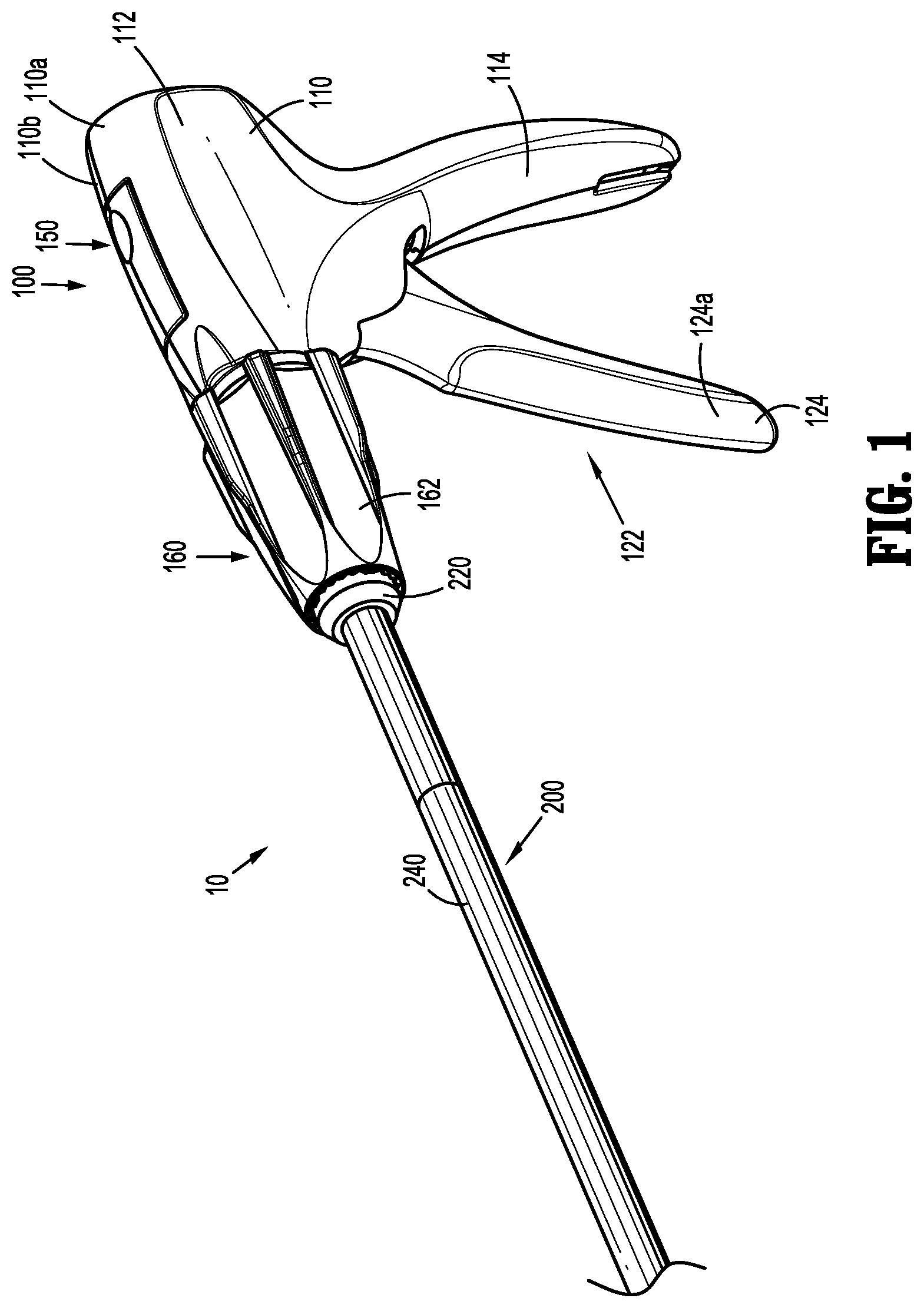
[0020] FIG. 1 is a front, perspective view of a surgical clip applier in accordance with aspects of the present disclosure including a handle assembly and an elongated assembly engaged therewith;
[0021] FIG. 2 is front, perspective view of the surgical clip applier shown in FIG. 1, with the elongated assembly removed from the handle assembly;
[0022] FIG. 3A is a side, perspective view of a distal end portion of the elongated assembly of FIGS. 1 and 2, configured to apply surgical clips;
[0023] FIG. 3B is a side, perspective view of a distal end portion of another elongated assembly configured for use with the handle assembly of FIG. 1, configured to apply surgical clips or fasteners;
[0024] FIG. 4 is a longitudinal, cross-sectional view of a portion of the handle assembly of the surgical clip applier of FIG. 1, including the elongated assembly of FIG. 1 engaged therewith;
[0025] FIG. 5 is a transverse, cross-sectional view taken across section line 5-5 of FIG. 4;
[0026] FIG. 6 is a rear, perspective view of a rotation knob assembly of the handle assembly of the surgical clip applier of FIG. 1;
[0027] FIG. 7 is an exploded, perspective view of the rotation knob assembly of FIG. 6; and
[0028] FIG. 8 is a longitudinal, partial cross-sectional view of the rotation knob assembly of FIG. 6.
DETAILED DESCRIPTION
[0029] The present disclosure provides rotation knob assemblies for surgical instruments. Although the rotation knob assemblies are discussed herein below as incorporated into surgical clip appliers, the rotation knob assemblies of the present disclosure may be incorporated into any suitable surgical instrument. Throughout this description, as is traditional when referring to relative positioning of a surgical instrument, the term "proximal" refers to a portion of the surgical instrument, or a component thereof, which is closer to a user, and the term "distal" refers to a portion of the surgical instrument or a component thereof which is further away from the user.
[0030] Turning to FIGS. 1-5, a surgical clip applier in accordance with aspects of the present disclosure is shown generally as clip applier 10. The clip applier 10 includes a handle assembly 100 and a plurality of elongated assemblies 200, 300 selectively connectable to the handle assembly 100. The handle assembly 100 is configured to operate each of the plurality of elongated assemblies 200, 300 upon connection thereto, and may be configured as a sterilizable, reusable component such that the handle assembly 100 may be repeatedly used with different and/or additional elongated assemblies 200, 300 during the course of one or more surgical procedures. The elongated assemblies 200, 300 may be configured as single-use disposable components, limited-use disposable components, or reusable components, depending upon a particular purpose and/or the configuration of the particular elongated assembly. In either configuration, the need for multiple handle assemblies is obviated and, instead, a user (e.g., a surgeon) need only select an appropriate elongated assembly 200, 300 and connect that elongated assembly 200, 300 to the handle assembly 100 in preparation for use.
[0031] The clip applier 10 will only be described to the extent necessary to fully disclose aspects of the present disclosure. For a detailed description of the structure and function of exemplary clip appliers (e.g., handle and elongated assemblies, and components thereof) suitable for use with the rotation knob assemblies of the present disclosure, reference may be made to Intl. Patent Appl. Publication Nos. WO/2017/059587, filed on Oct. 10, 2015, WO/2018/035796, filed on Aug. 26, 2016, and WO/2017/124217, filed on Jan. 18, 2016, and U.S. Patent Appl. Publication No. 2017-0128071, filed on Nov. 2, 2016, the entire contents of each of which are hereby incorporated herein by reference. It should be appreciated that the principles of the present disclosure are equally applicable to surgical instruments having other configurations such as, for example, powered surgical devices and/or different end effector assemblies (e.g., staplers, graspers, scissors, knives, etc.).
[0032] The handle assembly 100 is configured for use with different elongated assemblies such as, for example, elongated assembly 200 (FIGS. 1-3A) and elongated assembly 300 (FIG. 3B). The handle assembly 100, more specifically, is configured for both ratcheting use, e.g., in connection with elongated assembly 200 (FIGS. 1-3A), and non-ratcheting use, e.g., in connection with elongated assembly 300 (FIG. 3B).
[0033] As shown in FIGS. 1-3A, the elongated assembly 200 generally includes a proximal hub 220, an elongated shaft 240 extending distally from the proximal hub 220, an end effector assembly 260 disposed towards a distal end portion 240a of the elongated shaft 240, and an inner drive assembly (not shown) operably coupled between the handle assembly 100 and the end effector assembly 260 when the elongated assembly 200 is engaged with the handle assembly 100 to enable the sequential firing of at least one surgical clip (not shown) from the end effector assembly 260 about tissue. The end effector assembly 260 may be integrally formed with the elongated assembly 200 or may be a separate component releasably secured to the elongated assembly 200. The end effector assembly 260 of the elongated assembly 200 may be configured to fire surgical clips similar to those shown and described in U.S. Pat. Nos. 7,819,886 or 7,905,890, the entire contents of each of which are hereby incorporated herein by reference.
[0034] The proximal hub 220 of the elongated assembly 200 defines a plurality of indexing protrusions 222 annularly disposed thereabout towards a distal end portion 220a thereof, an annular channel 224 defined therein towards a proximal end portion 220b thereof, and a proximal tube extension 226 (FIG. 4) extending proximally from the proximal hub 220. The indexing protrusions 222 are configured for slidable receipt within longitudinally-extending grooves 168 defined within an outer knob 162 of a rotation knob assembly 160 of the clip applier 10 to rotationally fix the proximal hub 220 of the elongated assembly 200 relative to the rotation knob assembly 160 upon insertion of the proximal hub 220 therethrough (see also FIGS. 4 and 5). As such, in use, rotation of the outer knob 162 of the rotation knob assembly 160 relative to a housing 110 of the handle assembly 100 effects corresponding rotation of the elongated assembly 200 relative to the housing 110 of the handle assembly 100.
[0035] As shown in FIG. 3B, in conjunction with FIGS. 1 and 2, the elongated assembly 300 generally includes a proximal hub (not shown), an elongated shaft 340 extending distally from the proximal hub, an end effector assembly 360 disposed towards a distal end portion 340a of the elongated shaft 340, and an inner drive assembly (not shown) operably coupled between the handle assembly 100 and the end effector assembly 360 when the elongated assembly 300 is engaged with the handle assembly 100 to enable grasping and/or manipulation of tissue, retrieval of a surgical clip, and firing of a surgical clip about tissue. The end effector assembly 360 may be integrally formed with the elongated assembly 300 or may be a separate component releasably secured to the elongated assembly 300. The end effector assembly 360 of the elongated assembly 300 may be configured to fire surgical clips similar to those shown and described in U.S. Pat. No. 4,834,096, the entire contents of which are hereby incorporated herein by reference.
[0036] The proximal hub (not shown) of the elongated assembly 300 includes indexing protrusions and an annular channel similarly as described above with respect to the proximal hub 220 of the elongated assembly 200 and, in contrast to the proximal hub 220, does not include a proximal tube extension extending therefrom. The indexing protrusions rotationally fix the elongated assembly 300 relative to the rotation knob assembly 160 of the handle assembly 100 upon insertion of the proximal hub therethrough to enable rotation of the elongated assembly 300 relative to the housing 110 in response to rotation of the outer knob 162 of the rotation knob assembly 160 relative to the housing 110.
[0037] Although exemplary elongated assemblies 200, 300 configured for ratcheting and non-ratcheting use, respectively, are described above, it is contemplated that various other elongated assemblies for performing various different surgical tasks and/or having various different configurations suitable for ratcheting or non-ratcheting use may likewise be utilized with the handle assembly 100.
[0038] With continued reference to FIGS. 1, 2, and 4, the handle assembly 100 generally includes a housing 110, an actuation mechanism 120 including a trigger assembly 122 pivotably coupled to the housing 110 and a drive assembly 130 operably coupled to the trigger assembly 122, a ratchet mechanism 140 selectively operably associated with the drive assembly 130, a latch assembly 150 at least partially disposed within a cut-out defined within the housing 110 to enable manual manipulation thereof, and a rotation knob assembly 160 operable coupled to a nose 116 of the housing 110. The housing 110 supports and/or encloses the operating components of the handle assembly 100.
[0039] The housing 110 of handle assembly 100 may be formed from first and second housing halves 110a, 110b that cooperate to define a body portion 112 and a fixed handle portion 114 depending from the body portion 112. The body portion 112 of the housing 110 includes a distal nose 116 defining a distal opening 118a therethrough. A proximal end portion of a proximal hub of an elongated assembly, e.g., the proximal hub 220 of the elongated assembly 200 (FIGS. 1-3A) or the proximal hub (not shown) of the elongated assembly 300 (FIG. 3B), is configured to extend at least partially through the distal opening 118a of the distal nose 116 of the housing 110 when the elongated assembly 200, 300 is engaged with the handle assembly 100.
[0040] The distal nose 116 of the body portion 112 of the housing 110 further includes an annular recess 118b defined on an interior surface thereof surrounding the distal opening 118a. The annular recess 118b is configured to receive a proximal flange 184 of an intermediate collar 180 of the rotation knob assembly 160 to fixedly engage the intermediate collar 180 with the distal nose 116 of the body portion 112 of the housing 110, thereby rotatably engaging an outer knob 162 and an inner sleeve 170 of the rotation knob assembly 160 with the body portion 112 of the housing 110. To this end, the annular recess 118b and/or the proximal flange 184 may include keying features or other suitable features or materials (not shown) to facilitate rotationally-locked engagement therebetween.
[0041] The actuation mechanism 120 of the handle assembly 100 is configured to enable selective firing of one or more surgical clips (not shown) from an end effector assembly of an attached elongated assembly. The trigger assembly 122 of the actuation mechanism 120 includes a trigger 124, a linkage 126, and a biasing member 128. The trigger 124 includes a grasping portion 124a, an intermediate pivot portion 124b, and a proximal extension 124c. The grasping portion 124a of the trigger 124 extends from the body portion 112 of the housing 110 in opposed relation relative to the fixed handle portion 114 and is configured to facilitate grasping and manipulation of the trigger assembly 122. The intermediate pivot portion 124b of the trigger 124 is at least partially disposed within the housing 110 and defines a pivot aperture (not explicitly shown) configured to receive a pivot post 115 that extends transversely within the body portion 112 of the housing 110 so as to enable pivoting of the trigger 124 about the pivot post 115 and relative to the housing 110, e.g., between an un-actuated position, wherein the grasping portion 124a of the trigger 124 is spaced-apart relative to the fixed handle portion 114, and an actuated position, wherein the grasping portion 124a of the trigger 124 is approximated relative to the fixed handle portion 114.
[0042] The proximal extension 124c of the trigger 124 is disposed on an opposite side of the intermediate pivot portion 124b and, thus, the pivot post 115, as compared to the grasping portion 124a of the trigger 124. As such, pivoting of the grasping portion 124a to rotate in one direction, e.g., proximally towards the fixed handle portion 114, pivots the proximal extension 124c to rotate in the opposite direction, e.g., distally. The proximal extension 124c of the trigger 124 is pivotably coupled to a first or proximal end 126a of the linkage 126. The biasing member 128 is secured to and extends between the proximal extension 124c of the trigger 124 and a support (not shown) disposed within the fixed handle portion 114 of the housing 110. Pivoting of the grasping portion 124a towards the actuated position elongates the biasing member 128 storing energy therein such that, upon release of the grasping portion 124a, the grasping portion 124a is returned towards the un-actuated position under the bias of the biasing member 128. Although illustrated as an extension coil spring, the biasing member 128 may define any suitable configuration for biasing the grasping portion 124a of the trigger 124 towards the un-actuated position.
[0043] The drive assembly 130 includes a drive bar 132 having a proximal extension 132a and a ratchet rack 134. The drive bar 132 extends in a generally longitudinal direction and is longitudinally translatable relative to the housing 110. The proximal extension 132a of the drive bar 132 is pivotably coupled to a second or distal end 126b of the linkage 126 and, as noted above, the linkage 126 is coupled at its proximal end 126a to the proximal extension 124c of the trigger 124. As a result of this configuration, pivoting of the grasping portion 124a of the trigger 124 towards the actuated position urges the proximal extension 124c of the trigger 124 distally which, in turn, urges the linkage 126 distally to, in turn, urge the drive bar 132 distally.
[0044] The drive bar 132 is slidable through the body portion 112 of the housing 110, in response to actuation of the trigger 124, to urge a distal end portion 132b of the drive bar 132 into contact with a proximal actuator of an inner drive assembly (not shown) of an elongated assembly, e.g., elongated assembly 200 (FIGS. 1-3A) or elongated assembly 300 (FIG. 3B), engaged with the handle assembly 100 to fire a surgical clip supported at an end effector assembly of the elongated assembly. The drive bar 132, more specifically, is slidable from an un-actuated, proximal position, corresponding to the un-actuated position of the grasping portion 124a of the trigger 124, to an actuated, distal position, corresponding to the actuated position of the grasping portion 124a of the trigger 124, in order to urge the proximal actuator of the inner drive assembly (not shown) of the elongated assembly distally to fire a surgical clip supported at the end effector assembly of the elongated assembly.
[0045] The ratchet rack 134 of the drive assembly 130 extends along at least a portion of a surface (e.g., an underside surface) of the drive bar 132. The ratchet rack 134 is configured to selectively interface with the ratchet mechanism 140 to enable advancement of the drive bar 132 in either a ratcheting condition or a non-ratcheting condition.
[0046] The ratchet mechanism 140 enables ratcheting advancement of the drive assembly 130 when an elongated assembly configured for ratcheting actuation, e.g., elongated assembly 200, is connected to the handle assembly 100. The ratchet mechanism 140 includes a pawl assembly 141 and a cam assembly 145. The pawl assembly 141 includes a ratchet pawl 142 pivotably disposed about a pawl pin 144, which extends transversely within the housing 110. The ratchet pawl 142 is also transversely slidable about the pawl pin 144 and relative to the drive assembly 130. A transverse biasing member (not shown) biases the ratchet pawl 142 towards an off-set position relative to the ratchet rack 134 of the drive assembly 130, corresponding to the non-ratcheting condition of the ratchet mechanism 140 in which the ratchet pawl 142 is inhibited from operably engaging the ratchet rack 134 upon distal advancement of the drive bar 132. The ratchet pawl 142 is transversely slidable, against the bias, from the off-set position to an aligned position relative to the ratchet rack 132 of the drive assembly 130, corresponding to the ratcheting condition of the ratchet mechanism 140 in which ratchet pawl 142 is positioned to operably engage the ratchet rack 134 upon distal advancement of the drive bar 132.
[0047] The cam assembly 145 includes a cam arm 146 disposed about the pawl pin 144 adjacent the ratchet pawl 142. The cam arm 146 is slidable received, in fixed rotational orientation, within a slot 148a of a cam slider 148. A pawl biasing member 147 is coupled to and disposed between a free end of the cam arm 146 and the ratchet pawl 142 so as to bias the ratchet pawl 142 towards an operable orientation relative to the ratchet rack 134 of the drive assembly 130. The pawl biasing member 147 may be configured as a coil extension spring, although other configurations are also contemplated.
[0048] The cam slider 148 is slidable received within a longitudinally-extending guide track 119 defined within the housing 110 to confine the cam slider 148 to longitudinal translation within and relative to the housing 110. The cam slider 148 and the cam arm 146 are configured and dimensioned such that proximal translation of the cam slider 148 relative to the cam arm 146 urges the cam arm 146 transversely along the pawl pin 144 towards the ratchet pawl 142 to similarly urge the ratchet pawl 142 transversely along the pawl pin 144 from the off-set position towards the aligned position against the bias of the transverse biasing member (not shown). Return of the cam slider 148 distally permits the ratchet pawl 142 and, thus, the cam arm 146, to return transversely towards the off-set position under the bias of the transverse biasing member.
[0049] A cam slider biasing member 149 is retained within the guide track 119 of the housing 100, positioned to bias the cam slider 148 distally, and may be configured as a coil compression spring (although other configurations are also contemplated). As such, in the absence of other influence, the cam slider 148 is biased towards a distal-most position and, accordingly, the ratchet pawl 142 is biased towards the off-set position. In response to engagement of an elongated assembly for ratcheting use, e.g., elongated assembly 200, with the handle assembly 100, as shown in FIG. 4, the proximal tube extension 226 of the proximal hub 220 of the elongated assembly 200 contacts and urges the cam slider 148 of the ratchet mechanism 140 proximally to move the ratchet pawl 142 from the off-set position to the aligned position thereby engaging the ratcheting condition of the handle assembly 100.
[0050] The latch assembly 150 is configured to facilitate releasable locking engagement of an elongate assembly relative to the housing 110 of the handle assembly 100. The latch assembly 150 includes a latch lever 152, a pivot pin 154, and a biasing member 156. The latch lever 152 defines a distal engagement section 152a, an intermediate section 152b, and a proximal manipulatable section 152c. The distal engagement section 152a of the latch lever 152 includes an engagement tooth 158 extending therefrom. The engagement tooth 158 is configured to engage an elongated assembly inserted into the handle assembly 100. With respect elongated assembly 200, for example, upon insertion of the proximal hub 220 of the elongated assembly 200 into the handle assembly 100, the engagement tooth 158 is configured to cam over the proximal end portion 220b of the proximal hub 220 and into engagement within the annular channel 224 to thereby lock the elongated assembly 200 in engagement with the handle assembly 100.
[0051] The pivot pin 154 of the latch assembly 150 pivotably couples the intermediate section 152b of the lever latch 152 with the housing 110 such that urging of the proximal manipulation section 152c of lever latch 152 in a first direction into the housing 110, urges the distal engagement section 152a of the lever latch 152 in a second, opposite direction out of engagement with the annular channel 224 of the proximal hub 220 of the elongated assembly 200. The biasing member 156 is configured as a torsion spring biasing the distal engagement section 152a of the lever latch 152 towards an engaged position. However, other suitable configurations of the biasing member 156 are also contemplated. The proximal manipulation section 152c of the lever latch 152 is selectively depressible, against the bias of the biasing member 156, to urge the distal engagement section 152a towards a disengaged position.
[0052] The rotation knob assembly 160 is configured to enable selective rotation of an attached elongated assembly relative to the housing 110. As discussed above, the rotation knob assembly 160 is coupled to the distal nose 116 of the body portion 112 of the housing 110 and is configured to receive a proximal hub of an elongated assembly, e.g., the proximal hub 220 of the elongated assembly 200, coupled to the handle assembly 100 in fixed rotational engagement therewith to enable the selective rotation of the elongated assembly 200 relative to the housing 110 upon rotation of the outer knob 162 of the rotation knob assembly 160 relative to the housing 110.
[0053] Referring now to FIGS. 6-8, the rotation knob assembly 160 includes an outer knob 162, an inner sleeve 170, and intermediate collar 180. The rotation knob assembly 160 further includes a retaining clip 190 and screws 196. The outer knob 162 and the inner sleeve 170 are fixedly engaged to one another via the retaining clip 190 and the screws 196, and rotatable relative to the intermediate collar 180 which is radially disposed therebetween.
[0054] The outer knob 162 of the rotation knob assembly 160 may be formed from a polymeric material, e.g., a biocompatible, sterilizable plastic, or other suitable material, via molding or other suitable process. The outer knob 162 has a cone shaped-configuration tapering in diameter from a proximal portion 162a to a distal portion 162b thereof, although other suitable configurations are also contemplated. An exterior surface of the outer knob 162 is continuous and free of apertures (e.g., no screw holes), and includes a plurality of flutes 164 arranged radially thereabout to facilitate grasping or gripping of the outer knob 162 at any rotational orientation to enable rotation thereof.
[0055] With specific reference to FIG. 8, outer knob 162 of the rotation knob assembly 160 further includes a knob lumen 165 extending longitudinally therethrough along a longitudinal axis "X." The knob lumen 165 includes a proximal lumen portion 165a and a distal lumen portion 165b defined by an interior surface of the outer knob 162. The proximal lumen portion 165a of the knob lumen 165 has a diameter larger than a diameter of the distal lumen portion 165b of the knob lumen 165. A transverse wall or step 166 is disposed at the interface between the proximal and distal lumen portions 165a, 165b of the knob lumen 165, and faces proximally into the proximal lumen portion 165a.
[0056] Longitudinal apertures 167, e.g., a pair of opposed longitudinal apertures, are defined in the outer knob 162 along axes parallel to the longitudinal axis "X" defined through the knob lumen 165. The longitudinal apertures 167 each include an opening 167a defined in the transverse wall 166 that is in communication with the proximal lumen portion 165a of the knob lumen 165 and extends distally and linearly therefrom within the outer knob 162. Each of the longitudinal apertures 167 includes a non-threaded or smooth inner wall 167b extending along the entire length thereof configured to receive one of the screws 196 therein.
[0057] The distal lumen portion 165b of the knob lumen 165 includes grooves 168 arranged annularly in the interior surface of the outer knob 162 and disposed towards the distal end thereof which, as noted above, enable fixed rotational engagement of the proximal hub 220 of the elongated assembly 200 relative to the outer knob 162 of the rotation knob assembly 160 upon insertion of the proximal hub 220 therethrough (see FIGS. 2, 4, and 5). The distal lumen portion 165b of the knob lumen 165 further includes at least one ridge or bump 169 extending from the interior surface of the outer knob 162 and disposed towards the proximal end thereof which is configured to engage and be received within a cutout 173 defined in the inner sleeve 170.
[0058] With reference back to FIGS. 6-8, the inner sleeve 170 of the rotation knob assembly 160 may be formed from a metal, e.g., stainless steel, or other suitable material. The inner sleeve 170 has a cylindrical configuration including a sleeve lumen 171 extending longitudinally therethrough. The inner sleeve 170 further includes an outwardly-extending annular lip 172 disposed at a proximal end portion 170a of the inner sleeve 170, at least one notch or cut-out 173 defined in a distal end portion 170b of the inner sleeve 170, and an annular groove or channel 175 defined within an exterior surface of the inner sleeve 170 about an intermediate portion 170c of the inner sleeve 170 disposed between the proximal and distal end portions 170a, 170b.
[0059] The intermediate collar 180 of the rotation knob assembly 160 may be formed from a metal, e.g., stainless steel, or other suitable material. The intermediate collar 180 includes a body portion 182 and a proximal collar extension or flange 184 extending proximally and radially outwardly from the body portion 182. The intermediate collar 180 has a cylindrical configuration including a collar lumen 181 extending longitudinally therethrough. The intermediate collar 180 is configured to receive the inner sleeve 170 therethrough so that a bearing fit is established and an interior surface of the body portion 182 of the intermediate collar 180 that defines the collar lumen 181 provides a surface for the inner sleeve 170 to move (e.g., rotate). The diameter of the portion of the collar lumen 181 disposed within the proximal flange 184 is larger than the diameter of the portion of the lumen 181 disposed within the body portion 182 to receive the annular lip 172 of the inner sleeve 170 therein and prevent proximal longitudinal movement of the intermediate collar 180 relative to the inner sleeve 170.
[0060] The intermediate collar 180 further includes a proximal annular protrusion 186 extending outwardly from an exterior surface of the body portion 182 at a proximal end portion 182a of the body portion 182 in spaced longitudinal relation relative to the proximal flange 184, and a distal annular protrusion 188 extending outwardly from an exterior surface of the body portion 182 at a distal end portion 182b of the body portion 182.
[0061] As noted above, the intermediate collar 180 is radially disposed between the outer knob 162 and the inner sleeve 170. More specifically, the inner sleeve 170 is positioned within the intermediate collar 180 and the intermediate collar 180 is positioned within the proximal lumen portion 165a of the knob lumen 165 of the outer knob 162. The intermediate collar 180 defines a length less than a length of the inner sleeve 170 such that such that inner sleeve 170 extends distally beyond the intermediate collar 180 and into the distal lumen portion 165b of the knob lumen 165 of the outer knob 162.
[0062] With reference again to FIG. 4, in conjunction with FIGS. 6-8, the proximal flange 184 of the intermediate collar 180, as noted above, is configured for receipt within the annular recess 118b of the distal nose 116 of the body portion 112 of the housing 110, e.g., upon engagement of the first and second housing halves 110a, 110b (FIG. 1) forming the housing 110 with one another, thereby engaging the intermediate collar 180 with the body portion 112 of the housing 110 and, thus, coupling the outer knob 162 of the rotation knob assembly 160 about the distal nose 116 of the body portion 112 of the housing 110. The proximal flange 184 of the intermediate collar 180 defines openings 185 for receiving tabs (not shown) extending from the distal nose 116 of the housing 110 for rotationally locking the intermediate collar 180 relative to the housing 110.
[0063] While the intermediate collar 180 is longitudinally and rotationally fixed relative to the housing 110, the outer knob 162 and the inner sleeve 170 are fixed to one another and together rotatable about and relative to the intermediate collar 180 and, thus, relative to the housing 110, e.g., to enable rotation of the elongated assembly 200 relative to the housing 110. The proximal and distal annular protrusions 186, 188 of the intermediate collar 180 define bearing surfaces about which the outer knob 162 rotates, facilitating smooth rotation of the outer knob 162 relative to intermediate collar 180.
[0064] The retaining clip 190 and the screws 196 fix the outer knob 162 and the inner sleeve 170 to one another to enable the outer knob 162 and the inner sleeve 170 to rotate together relative to the intermediate collar 180 and the housing 110. The retaining clip 190 includes curved body 192 having a substantially semi-annular or semi-circular configuration (e.g., a c-shaped or u-shaped cross-section) including first and second brackets or prongs 194 extending from opposed ends thereof. The curved body 192 is configured for positioning within the annular groove 175 of the inner sleeve 170 to mount the retaining clip 190 to the inner sleeve 170, and the prongs 194 are configured for positioning against the transverse wall 166 disposed within the knob lumen 165 of the outer knob 162. Each of the prongs defines an opening 195 therethrough that is configured to align with the respective opening 167a of the longitudinal apertures 167 of the outer knob 162. One or more intermediate prongs (not shown) may extend from the curved body 192 of the retaining clip 190 (e.g., the retaining clip 190 may have an e-shaped cross-section) to engage and retain the curved body 192 to the inner sleeve 170.
[0065] The screws 196 are configured to secure the retaining clip 190 within the outer knob 162 to thereby retain the inner sleeve 170 and the outer knob 162 in fixed engagement with one another. Each of the screws 196 includes a head 196a and a threaded shank 196b extending from the head 196a. The threaded shanks 196b of the screws 196 are configured as thread-forming or thread-cutting screws to form mating threads in the non-threaded inner wall 167b of the longitudinal apertures 167 of the outer knob 162 to retain the screws 196 therein and minimize loosening of the screws 196. Alternatively, the threaded shanks 196b of the screws 196 may be configured for threaded engagement with pre-formed threads of the longitudinal apertures 167 of the outer knob 162.
[0066] The screws 196 are received within the longitudinal apertures 167 of the outer knob 162 and are oriented such that the threaded shanks 196b are engaged with the respective opening 195 of the retaining clip 190 and the longitudinal apertures 167 of the outer knob 162, and the heads 196a of the screws 196 are positioned or seated against the respective prong 194 of the retaining clip 190.
[0067] The rotation knob assembly 160 is assembled by sliding the inner sleeve 170 through the lumen 181 of the intermediate collar 180 until the body portion 182 of the intermediate collar 180 is disposed over the proximal end portion 170a of the inner sleeve 170 and the proximal flange 184 is coaxial with the annular lip 172. The curved body 192 of the retaining clip 190 is then snapped into the annular groove 175 of the inner sleeve 170. This assembly is loaded into the outer knob 162 until the cut-out 173 of the inner sleeve 170 engages the ridge 169 of the outer knob 162 to fix the inner sleeve 170 to the outer knob 162, and the prongs 194 of the retaining clip 190 abut the transverse wall 166 of the outer knob 162 with the openings 195 of the retaining clip 190 aligned with the longitudinal apertures 167 of the outer knob 162. The screws 196 are then driven through the openings 195 of the retaining clip 190 and into the longitudinal apertures 167 of the outer knob 162 until the heads 196a of the screws 196 are seated against the prongs 194 of the retaining clip 190 to affix the retaining clip 190 and thus, the inner sleeve 170, to the outer knob 162. Once the screws 196 are properly seated, the rotation knob assembly 160 is locked together. The assembled rotation knob assembly 160 may then be secured to the housing 110 of the handle assembly 100 by the intermediate collar 180, as described above.
[0068] Referring generally to FIGS. 1-8, a method of inserting and engaging an elongated assembly, e.g., elongated assembly 200, with the handle assembly 100 and use of the same are described in accordance with aspects of the present disclosure. In order to engage the elongated assembly 200 with the handle assembly 100, the proximal hub 220 of the elongated assembly 200 is inserted into the knob lumen 165 of the outer knob 162 and advanced proximally into the sleeve lumen 171 of the inner sleeve 170 and into the distal nose 116 of the housing 110. Upon insertion of the proximal hub 220 through the rotation knob assembly 160, the indexing protrusions 222 of the proximal hub 220 are slidably received within the grooves 168 of the outer knob 172 to rotationally fix the proximal hub 220 relative to the outer knob 172. As the proximal hub 220 enters the housing 110, the proximal hub 220 receives the distal end portion 132b of the drive bar 132 of the drive assembly 130, the engagement tooth 158 of the latch assembly 150 cams over the proximal end portion 220b of the proximal hub 220 and into engagement therewith to thereby rotatably engage the proximal hub 220 relative to the housing 110, and the proximal extension tube 226 of the proximal hub 220 is translated into contact with the cam slider 148 of the ratchet mechanism 140 for ratcheting use of the drive assembly 130.
[0069] With the elongated assembly 200 engaged with the handle assembly 100, the handle assembly 100 may be manipulated and/or the outer knob 162 of the rotation knob assembly 160 may be rotated to position the end effector assembly 260 of the elongated assembly 200 about tissue to be treated. Once the end effector assembly 260 is positioned as desired, the trigger 124 of the handle assembly 100 is pivoted towards the fixed handle portion 114 of the housing 110 to urge the linkage 126 distally which, in turn, urges the drive bar 132 distally through the housing 110 to drive the proximal actuator of the inner drive assembly (not shown) of the elongated assembly 200 distally through the elongated assembly 200 to fire and form a surgical clip from the end effector assembly 260 about tissue. The above may be repeated to fire and form several surgical clips about tissue, as necessary.
[0070] In order to disengage the elongated assembly 200 from the handle assembly 100, e.g., for cleaning and/or sterilization, or to replace the elongated assembly 200 with another elongated assembly, the lever latch 152 of the latch assembly 150 is depressed inwardly into the housing 110 to disengage the proximal hub 220 of the elongated assembly 200, thus enabling the proximal hub 220 to be withdrawn distally from the housing 110 and the rotation knob assembly 170.
[0071] It should be understood that the foregoing description is only illustrative of the present disclosure. Various alternatives and modifications can be devised by those skilled in the art without departing from the disclosure. Accordingly, the present disclosure is intended to embrace all such alternatives, modifications and variances. The embodiments described with reference to the attached drawing figures are presented only to demonstrate certain examples of the disclosure. Other elements, steps, methods and techniques that are insubstantially different from those described above and/or in the appended claims are also intended to be within the scope of the disclosure.
* * * * *
D00000
D00001
D00002
D00003
D00004
D00005
D00006
XML
uspto.report is an independent third-party trademark research tool that is not affiliated, endorsed, or sponsored by the United States Patent and Trademark Office (USPTO) or any other governmental organization. The information provided by uspto.report is based on publicly available data at the time of writing and is intended for informational purposes only.
While we strive to provide accurate and up-to-date information, we do not guarantee the accuracy, completeness, reliability, or suitability of the information displayed on this site. The use of this site is at your own risk. Any reliance you place on such information is therefore strictly at your own risk.
All official trademark data, including owner information, should be verified by visiting the official USPTO website at www.uspto.gov. This site is not intended to replace professional legal advice and should not be used as a substitute for consulting with a legal professional who is knowledgeable about trademark law.