Bilateral Spring For Surgical Instruments And Surgical Instruments Including The Same
Baril; Jacob C. ; et al.
U.S. patent application number 16/433049 was filed with the patent office on 2020-02-13 for bilateral spring for surgical instruments and surgical instruments including the same. The applicant listed for this patent is Covidien LP. Invention is credited to Jacob C. Baril, Matthew A. Dinino, Roy J. Pilletere, Justin Thomas.
| Application Number | 20200046362 16/433049 |
| Document ID | / |
| Family ID | 67614468 |
| Filed Date | 2020-02-13 |


| United States Patent Application | 20200046362 |
| Kind Code | A1 |
| Baril; Jacob C. ; et al. | February 13, 2020 |
BILATERAL SPRING FOR SURGICAL INSTRUMENTS AND SURGICAL INSTRUMENTS INCLUDING THE SAME
Abstract
A handle assembly of a surgical instrument includes a housing, a trigger pivotably coupled to the housing, a drive bar disposed within the housing and operably coupled to the trigger such that pivoting of the trigger translates the drive bar, and a bilateral spring disposed within the housing and operably coupled to at least one of the trigger or the drive bar. The trigger is movable relative to the housing between first, second, and third positions wherein the first position is disposed between the second and third positions. The bilateral spring includes a compression spring configured to compress upon movement of the trigger in a first direction from the first position towards the second position to establish a first bias, and to compress upon movement of the trigger in a second, opposite direction from the first position towards the third position to establish a second bias.
| Inventors: | Baril; Jacob C.; (Norwalk, CT) ; Pilletere; Roy J.; (North Haven, CT) ; Thomas; Justin; (New Haven, CT) ; Dinino; Matthew A.; (Newington, CT) | ||||||||||
| Applicant: |
|
||||||||||
|---|---|---|---|---|---|---|---|---|---|---|---|
| Family ID: | 67614468 | ||||||||||
| Appl. No.: | 16/433049 | ||||||||||
| Filed: | June 6, 2019 |
Related U.S. Patent Documents
| Application Number | Filing Date | Patent Number | ||
|---|---|---|---|---|
| 62717988 | Aug 13, 2018 | |||
| Current U.S. Class: | 1/1 |
| Current CPC Class: | A61B 2017/2922 20130101; A61B 2017/00367 20130101; A61B 2017/0046 20130101; A61B 17/128 20130101; A61B 2017/00477 20130101; A61B 17/1285 20130101; A61B 2017/2929 20130101; A61B 17/2909 20130101 |
| International Class: | A61B 17/128 20060101 A61B017/128 |
Claims
1. A handle assembly of a surgical instrument, comprising: a housing; a trigger pivotably coupled to the housing and movable relative thereto between a first position, a second position, and a third position, wherein the first position is disposed between the second and third positions; a drive bar disposed within the housing and operably coupled to the trigger such that pivoting of the trigger translates the drive bar; and a bilateral spring disposed within the housing and operably coupled to at least one of the trigger or the drive bar, the bilateral spring including a compression spring, wherein the compression spring is configured to compress upon movement of the trigger in a first direction from the first position towards the second position to establish a first bias biasing the trigger back towards the first position, and to compress upon movement of the trigger in a second, opposite direction from the first position towards the third position to establish a second bias biasing the trigger back towards the first position.
2. The handle assembly according to claim 1, wherein movement of the trigger in the first direction from the first position towards the second position compresses the bilateral spring to thereby compress the compression spring to establish the first bias.
3. The handle assembly according to claim 1, wherein movement of the trigger in the second, opposite direction from the first position towards the third position extends the bilateral spring to compress the compression spring to establish the second bias.
4. The handle assembly according to claim 1, further comprising at least one linkage operably coupling the trigger and the drive bar such that pivoting of the trigger translates the drive bar.
5. The handle assembly according to claim 4, wherein the bilateral spring is coupled between at least two of the housing, the trigger, the drive bar, or the at least one linkage.
6. The handle assembly according to claim 1, wherein the bilateral spring includes first and second arms each disposed in oppositely-facing directions relative to one another and overlapping one another, wherein the compression spring is disposed about overlapping portions of the first and second arms.
7. The handle assembly according to claim 6, wherein each of the first and second arms includes an attachment end portion and a retention end portion, the attachment end portions configured to facilitate operable coupling of the bilateral spring within the housing and the retention end portions configured to retain the compression spring therebetween.
8. The handle assembly according to claim 1, further including a latch mechanism operably coupled to the housing and configured to releasably engage an elongated assembly inserted into the housing.
9. The handle assembly according to claim 1, further comprising a rotation knob assembly rotatably supported at a distal portion of the housing.
10. The handle assembly according to claim 1, wherein the housing includes a body portion and a fixed handle portion, the trigger pivotable away from the fixed handle portion from the first position to the second position and pivotable towards the fixed handle portion from the first position to the third position.
11. A surgical instrument, comprising: a housing; an elongated assembly extending distally from the housing and supporting an end effector towards a distal end thereof; a trigger pivotably coupled to the housing and movable relative thereto between a first position, a second position, and a third position, wherein the first position is disposed between the second and third positions; a drive bar disposed within the housing and operably coupled to the trigger such that pivoting of the trigger translates the drive bar to actuate the end effector; and a bilateral spring disposed within the housing and operably coupled to at least one of the trigger or the drive bar, the bilateral spring including a compression spring, wherein the compression spring is configured to compress upon movement of the trigger in a first direction from the first position towards the second position to establish a first bias biasing the trigger back towards the first position, and to compress upon movement of the trigger in a second, opposite direction from the first position towards the third position to establish a second bias biasing the trigger back towards the first position.
12. The surgical instrument according to claim 11, wherein movement of the trigger in the first direction from the first position towards the second position compresses the bilateral spring to thereby compress the compression spring to establish the first bias.
13. The surgical instrument according to claim 11, wherein movement of the trigger in the second, opposite direction from the first position towards the third position extends the bilateral spring to compress the compression spring to establish the second bias.
14. The surgical instrument according to claim 11, further comprising at least one linkage operably coupling the trigger and the drive bar such that pivoting of the trigger translates the drive bar.
15. The surgical instrument according to claim 11, wherein the bilateral spring includes first and second arms each disposed in oppositely-facing directions relative to one another and overlapping one another, wherein the compression spring is disposed about overlapping portions of the first and second arms.
16. The surgical instrument according to claim 15, wherein each of the first and second arms includes an attachment end portion and a retention end portion, the attachment end portions configured to facilitate operable coupling of the bilateral spring within the housing and the retention end portions configured to retain the compression spring therebetween.
17. The surgical instrument according to claim 11, further including a latch mechanism operably coupled to the housing and configured to releasably engage the elongated assembly therein.
18. The surgical instrument according to claim 11, further comprising a rotation knob assembly rotatably supported at a distal portion of the housing.
19. The surgical instrument according to claim 11, wherein the housing includes a body portion and a fixed handle portion, the trigger pivotable away from the fixed handle portion from the first position to the second position and pivotable towards the fixed handle portion from the first position to the third position.
20. The surgical instrument according to claim 11, wherein engagement of the elongated assembly with the housing urges the trigger from the first position to the second position against the first bias of the bilateral spring.
Description
CROSS-REFERENCE TO RELATED APPLICATION
[0001] This application claims the benefit of and priority to U.S. Provisional Patent Application No. 62/717,988 filed Aug. 13, 2018, the entire disclosure of which is incorporated by reference herein.
BACKGROUND
Technical Field
[0002] The present disclosure relates to surgical instruments such as, for example, surgical clip appliers. More particularly, the present disclosure relates to a bilateral spring for surgical instruments and a surgical instrument including the same.
Description of Related Art
[0003] Surgical clip appliers are used for a number of distinct and useful surgical procedures. Surgical clip appliers having various sizes (e.g., diameters), that are configured to apply a variety of diverse surgical clips are capable of applying a single or multiple surgical clips during an entry to the body cavity. Such surgical clips are typically fabricated from a biocompatible material and are usually compressed over tissue. Once applied to tissue, the compressed surgical clip terminates the flow of fluid therethrough.
SUMMARY
[0004] As detailed herein and shown in the drawing figures, as is traditional when referring to relative positioning on a surgical instrument, the term "proximal" refers to the end of the apparatus or component thereof which is closer to the user and the term "distal" refers to the end of the apparatus or component thereof which is further away from the user. Further, to the extent consistent, any or all of the aspects and features detailed herein may be used in conjunction with any or all of the other aspects and features detailed herein.
[0005] A handle assembly of a surgical instrument, in accordance with an aspect of the present disclosure, includes a housing, a trigger, a drive bar, and a bilateral spring. The trigger is pivotably coupled to the housing and movable relative thereto between a first position, a second position, and a third position. The first position is disposed between the second and third positions. The drive bar is disposed within the housing and operably coupled to the trigger such that pivoting of the trigger translates the drive bar.
[0006] The bilateral spring is disposed within the housing and operably coupled to at least one of the trigger or the drive bar. The bilateral spring includes a compression spring configured to compress upon movement of the trigger in a first direction from the first position towards the second position to establish a first bias biasing the trigger back towards the first position. The compression spring is also configured to compress upon movement of the trigger in a second, opposite direction from the first position towards the third position to establish a second bias biasing the trigger back towards the first position.
[0007] In aspects of the present disclosure, movement of the trigger in the first direction from the first position towards the second position compresses the bilateral spring to thereby compress the compression spring to establish the first bias. Additionally or alternatively, movement of the trigger in the second, opposite direction from the first position towards the third position extends the bilateral spring to compress the compression spring to establish the second bias.
[0008] In aspects of the present disclosure, at least one linkage operably couples the trigger and the drive bar such that pivoting of the trigger translates the drive bar. In such aspects, the bilateral spring may be coupled between two or more of the housing, the trigger, the drive bar, or the at least one linkage.
[0009] In aspects of the present disclosure, the bilateral spring includes first and second arms each disposed in oppositely-facing directions relative to one another and overlapping one another. In such aspects, the compression spring is disposed about overlapping portions of the first and second arms. Additionally, each of the first and second arms may include an attachment end portion and a retention end portion, wherein the attachment end portions are configured to facilitate operable coupling of the bilateral spring within the housing and wherein the retention end portions are configured to retain the compression spring therebetween.
[0010] In aspects of the present disclosure, a latch mechanism is operably coupled to the housing and configured to releasably engage an elongated assembly inserted into the housing. Additionally or alternatively, a rotation knob assembly is rotatably supported at a distal portion of the housing.
[0011] In aspects of the present disclosure, the housing includes a body portion and a fixed handle portion. In such aspects, the trigger is pivotable away from the fixed handle portion from the first position to the second position and pivotable towards the fixed handle portion from the first position to the third position.
[0012] A surgical instrument, provided in accordance with further aspects of the present disclosure, includes a housing, an elongated assembly extending distally from the housing and supporting an end effector towards a distal end thereof, a trigger pivotably coupled to the housing, a drive bar disposed within the housing and operably coupled to the trigger such that pivoting of the trigger translates the drive bar to actuate the end effector, and a bilateral spring disposed within the housing and operably coupled to at least one of the trigger or the drive bar. The trigger is and movable relative to the housing between a first position, a second position, and a third position wherein the first position is disposed between the second and third positions.
[0013] The bilateral spring includes a compression spring configured to compress upon movement of the trigger in a first direction from the first position towards the second position to establish a first bias biasing the trigger back towards the first position, and to compress upon movement of the trigger in a second, opposite direction from the first position towards the third position to establish a second bias biasing the trigger back towards the first position.
[0014] In aspects of the present disclosure, movement of the trigger in the first direction from the first position towards the second position compresses the bilateral spring to thereby compress the compression spring to establish the first bias. Additionally or alternatively, movement of the trigger in the second, opposite direction from the first position towards the third position extends the bilateral spring to compress the compression spring to establish the second bias.
[0015] In aspects of the present disclosure, at least one linkage operably couples the trigger and the drive bar such that pivoting of the trigger translates the drive bar.
[0016] In aspects of the present disclosure, the bilateral spring includes first and second arms each disposed in oppositely-facing directions relative to one another and overlapping one another. In such aspects, the compression spring is disposed about overlapping portions of the first and second arms. Additionally, each of the first and second arms may include an attachment end portion and a retention end portion, wherein the attachment end portions are configured to facilitate operable coupling of the bilateral spring within the housing and wherein the retention end portions are configured to retain the compression spring therebetween.
[0017] In aspects of the present disclosure, a latch mechanism is operably coupled to the housing and configured to releasably engage an elongated assembly inserted into the housing. Additionally or alternatively, a rotation knob assembly is rotatably supported at a distal portion of the housing.
[0018] In aspects of the present disclosure, the housing includes a body portion and a fixed handle portion. In such aspects, the trigger is pivotable away from the fixed handle portion from the first position to the second position and pivotable towards the fixed handle portion from the first position to the third position.
[0019] In aspects of the present disclosure, engagement of the elongated assembly with the housing urges the trigger from the first position to the second position against the first bias of the bilateral spring.
BRIEF DESCRIPTION OF THE DRAWINGS
[0020] Aspects and features of the presently-disclosed bilateral spring for surgical clip instruments and surgical instruments including the same are described in detail with reference to the drawing figures wherein like reference numerals identify similar or identical structural elements and:
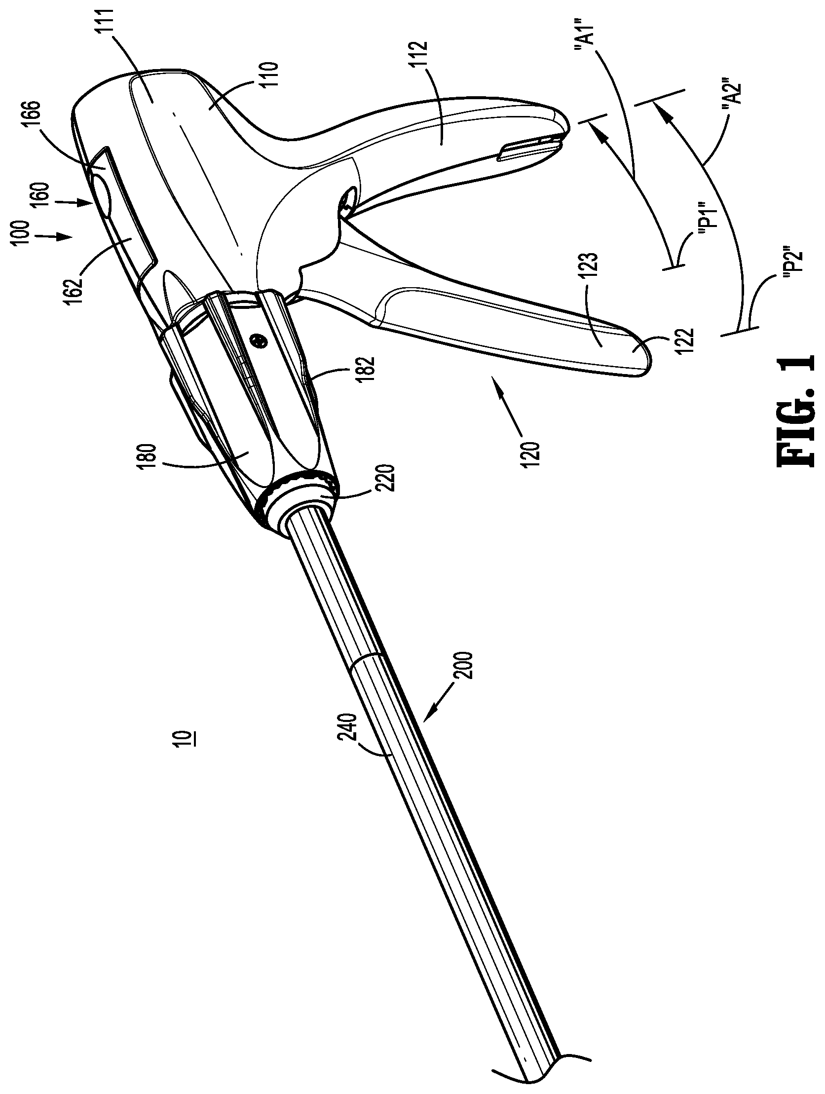
[0021] FIG. 1 is a front, perspective view of a surgical clip applier provided in accordance with the present disclosure including a handle assembly having an elongated assembly engaged therewith;
[0022] FIG. 2 is front, perspective view of the surgical clip applier of FIG. 1 with the elongated assembly removed from the handle assembly;
[0023] FIG. 3A is a side, perspective view of a distal end portion of the elongated assembly of FIGS. 1 and 2;
[0024] FIG. 3B is a side, perspective view of a distal end portion of another elongated assembly configured for use with the surgical clip applier of FIG. 1;
[0025] FIG. 4 is a side view of a proximal portion of the surgical clip applier of FIG. 1 with a portion of the housing of the handle assembly removed to illustrate the internal components therein;
[0026] FIG. 5 is an enlarged, side view of the area of detail indicated as "5" in FIG. 4;
[0027] FIG. 6 is a perspective view of a bilateral spring provided in accordance with the present disclosure and configured for use with the surgical clip applier of FIG. 1;
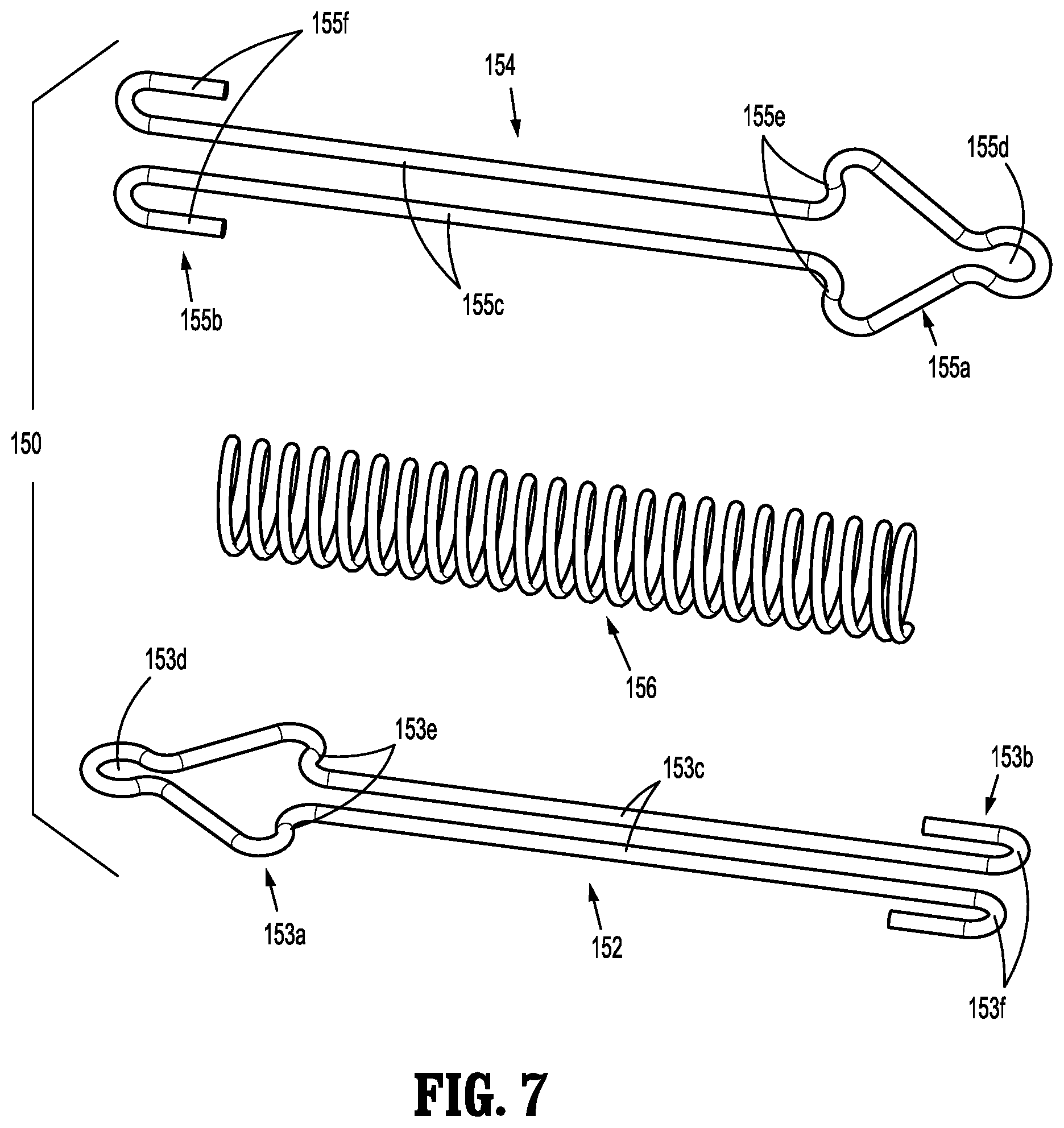
[0028] FIG. 7 is an exploded, perspective view of the bilateral spring of FIG. 6; and
[0029] FIGS. 8A-8C are side views of the bilateral spring of FIG. 6 in a neutral position, an extended position, and a compressed position, respectively.
DETAILED DESCRIPTION
[0030] The present disclosure provides a bilateral spring for surgical instruments and surgical instruments including the same. Although detailed herein as incorporated into a surgical clip applier, the bilateral spring of the present disclosure may alternatively be incorporated into any suitable surgical instrument.
[0031] Turning to FIGS. 1-2, a surgical clip applier embodying the aspects and features of the present disclosure is shown generally identified by reference numeral 10. Surgical clip applier 10 generally includes a handle assembly 100 and a plurality of elongated assemblies 200, 300 (FIG. 3B) selectively connectable to handle assembly 100. Handle assembly 100 is configured to operate each of the plurality of elongated assemblies 200, 300 (FIG. 3B) upon connection thereto, and may be configured as a sterilizable, reusable component such that handle assembly 100 may be repeatedly used with different and/or additional elongated assemblies 200, 300 (FIG. 3B) during the course of one or more surgical procedures. The elongated assemblies 200, 300 (FIG. 3B) may be configured as single-use disposable components, limited-use disposable components, or reusable components, depending upon a particular purpose and/or the configuration of the particular elongated assembly. In either configuration, the need for multiple handle assemblies 100 is obviated and, instead, the surgeon need only select an appropriate elongated assembly 200, 300 (FIG. 3B) and connect that elongated assembly to handle assembly 100 in preparation for use.
[0032] With additional reference to FIGS. 3A and 3B, as noted above, handle assembly 100 is configured for use with different elongated assemblies such as, for example, elongated assembly 200 (FIGS. 1-3A) and elongated assembly 300 (FIG. 3B). Elongated assemblies 200, 300 are described briefly below. A more detailed discussion of elongated assemblies, e.g., elongated assemblies 200, 300, configured for use with handle assembly 100 can be found in International Appln. Pub. Nos. WO2018/035796, WO2017/124217, and/or WO2017/059587, the entire content of each of which is hereby incorporated herein by reference.
[0033] Referring to FIGS. 1-3A, elongated assembly 200 generally includes a proximal hub 220, an elongated shaft 240 extending distally from proximal hub 220, an end effector 260 disposed towards a distal end portion of elongated shaft 240, and an inner drive assembly 280 (FIG. 4) operably coupled between handle assembly 100 and end effector 260 when elongated assembly 200 is engaged with handle assembly 100 to enable the sequential firing of at least one surgical clip (not shown) about tissue. End effector 260 of elongated assembly 200 may be configured to fire surgical clips similar to those shown and described in U.S. Pat. Nos. 7,819,886 or 7,905,890, the entire content of each of which is hereby incorporated herein by reference.
[0034] Proximal hub 220 of elongated assembly 200 defines a plurality of indexing protrusions 222 annularly disposed thereabout towards a distal end portion thereof. Indexing protrusions 222, as detailed below, are configured for slidable receipt within longitudinally-extending grooves 186 defined within outer knob 182 of rotation knob assembly 180 to rotationally fix proximal hub 220 of elongated assembly 200 relative to rotation knob assembly 180 upon insertion of proximal hub 220 therethrough. As such, in use, rotation of outer knob 182 of rotation knob assembly 180 relative to housing 110 of handle assembly 100 effects corresponding rotation of elongated assembly 200 relative to housing 110.
[0035] Referring to FIG. 3B, in conjunction with FIGS. 1 and 2, elongated assembly 300 generally includes a proximal hub (not shown), an elongated shaft 340 extending distally from the proximal hub, an end effector 360 disposed towards a distal end portion of elongated shaft 340, and an inner drive assembly (not shown) operably coupled between handle assembly 100 and end effector 360 when elongated assembly 300 is engaged with handle assembly 100 to enable grasping and/or manipulation of tissue, retrieval of a surgical clip, and firing of the surgical clip about tissue. It is contemplated that end effector 360 of elongated assembly 300 may be configured to fire surgical clips similar to those shown and described in U.S. Pat. No. 4,834,096, the entire content of which is hereby incorporated herein by reference.
[0036] The proximal hub (not shown) of elongated assembly 300 includes indexing protrusions similarly as detailed above with respect to proximal hub 220 of elongated assembly 200 (see FIG. 2) such that elongated assembly 300 is rotationally fix relative to rotation knob assembly 180 upon insertion of proximal hub 220 therethrough to enable rotation of elongated assembly 300 relative to housing 110 of handle assembly 100 in response to rotation of outer knob 182 of rotation knob assembly 180 relative to housing 110.
[0037] Referring to FIGS. 1-5, although exemplary elongated assemblies 200, 300 are detailed above, it is contemplated that various other elongated assemblies for performing various different surgical tasks and/or having various different configurations may likewise be utilized with handle assembly 100. As can be appreciated, the actuation length required to actuate an elongated assembly may vary between different elongated assemblies such as, for example, depending upon the particular configuration of the elongated assembly. Handle assembly 100, as detailed below, is configured for use with various different elongated assemblies having various different actuation lengths without providing any dead space at the beginning or end of the actuation stroke of trigger 122 of actuation mechanism 120 of handle assembly 100.
[0038] Handle assembly 100 of surgical clip applier 10 generally includes a housing 110, an actuation mechanism 120 operably associated with housing 110, a latch assembly 160 operably associated with housing 110, and a rotation knob assembly 180 operably coupled to a distal portion of housing 110. Housing 110 of handle assembly 100 supports and/or encloses the operating components of handle assembly 100 and defines a body portion 111 and a fixed handle portion 112 depending from body portion 111. Body portion 111 of housing 110 includes an internal pivot post 114 extending transversely within body portion 111 and a distal opening 118 through which a proximal end portion of elongated assembly 200 extends when elongated assembly 200 is engaged with handle assembly 100.
[0039] With particular reference to FIGS. 4-5, actuation mechanism 120 is operably supported by housing 110 and includes a trigger 122, a drive bar 130, a linkage assembly 140, and a bilateral spring 150. Trigger 122 includes a grasping portion 123, an intermediate pivot portion 124, and a proximal extension 125. Grasping portion 123 of trigger 122 extends downwardly from body portion 111 of housing 110 in opposed relation relative to fixed handle portion 112 of housing 110. Grasping portion 123 is configured to facilitate grasping and manipulation of trigger 122. Intermediate pivot portion 124 of trigger 122 is at least partially disposed within housing 110 and defines a pivot aperture 126 that is configured to receive pivot post 114 of housing 110 so as to enable pivoting of trigger 122 about pivot post 114 and relative to housing 110, e.g., between an un-actuated position, wherein grasping portion 123 of trigger 122 is spaced-apart relative to fixed handle portion 112, and an actuated position, wherein grasping portion 123 of trigger 122 is approximated relative to fixed handle portion 112.
[0040] Proximal extension 125 of trigger 122 is disposed on an opposite side of intermediate pivot portion 124 and, thus, pivot post 114, as compared to grasping portion 123 of trigger 122. As such, pivoting of grasping portion 123 to rotate in one direction, e.g., proximally towards fixed handle portion 112, pivots proximal extension 125 to rotate in the opposite direction, e.g., distally.
[0041] Drive bar 130 is slidably disposed within body portion 111 of housing 110 in longitudinal alignment with an inner drive assembly of an elongated assembly engaged with handle assembly 100, e.g., inner drive assembly 280 of elongated assembly 200 (see FIG. 4). In this manner, when elongated assembly 200 is engaged with handle assembly 100, distal sliding of drive bar 130 through body portion 111 of housing 110 urges drive bar 130 distally to, in turn, urge the inner drive assembly 280 (or portion(s) thereof) distally to actuate end effector 260 of elongated assembly 200, e.g., to apply, form, or close a surgical clip supported at end effector 260.
[0042] Continuing with reference to FIGS. 4-5, linkage assembly 140 operably couples trigger 122 with drive bar 130 and includes a first linkage 142, a second linkage 144, and a third linkage 146. First linkage 142 is pivotably coupled to proximal extension 125 of trigger 122 towards a first end (not shown) of first linkage 142. Second and third linkages 144, 146, respectively, are each pivotably coupled to a second end 143 of first linkage 142 at respective first ends 145a, 147a of second and third linkages 144, 146. A second end 145b of second linkage 144 is pivotably coupled to drive bar 130, while a second end 147b of third linkage 146 is pivotably coupled to body portion 111 of housing 110. Thus, the pivot point between first linkage 142 and proximal extension 125 of trigger 122, the pivot point between first linkage 142 and second and third linkages 144, 146, respectively, and the pivot point between second linkage 144 and drive bar 130 are movable pivot points (e.g., movable relative to housing 110), while the pivot point between third linkage 146 and housing 110 is a fixed pivot point (e.g., fixed relative to housing 110).
[0043] Upon actuation of trigger 122, e.g., proximal pivoting of grasping portion 123 of trigger 122, proximal extension 125 is moved in a counter-clockwise direction (from the orientation illustrated in FIG. 4), thereby urging first linkage 142 towards drive bar 130. This movement of first linkage 142 towards drive bar 130, in turn, urges first ends 145a, 147a of second and third linkages 144, 146, respectively, towards drive bar 130 to, in turn, urge second end 145b of second linkage 144 distally such that drive bar 130 is translated distally through body portion 111 of housing 110. Return of trigger 122 distally, e.g., clockwise from the orientation illustrated in FIG. 4, effects opposite movement of linkages 142, 144, 146 to thereby return drive bar 130 proximally.
[0044] Bilateral spring 150 is coupled at a first end 151a thereof to an intermediate portion 145c of second linkage 144, e.g., between first and second ends 145a, 145b, respectively, thereof, and at a second end 151b thereof to second end 147b of third linkage 146 and/or to body portion 111 of housing 110 at the pivot point where second end 147b of third linkage 146 is pivotably coupled to body portion 111 of housing 110. In this manner, bilateral spring 150 is extended from its neutral position, corresponding to a position "P1" of trigger 122, in response to actuation of trigger 122 proximally from position "P1" towards fixed handle portion 112 of housing 110, and is compressed from its neutral position in response to movement of trigger 122 distally from position "P1," e.g., away from fixed handle portion 112 of housing 110. Other suitable positionings wherein bilateral spring 150 is compressed upon movement of trigger 122 from position "P1" in one direction and extended upon movement of trigger 122 from position "P1" in a second, opposite direction are also contemplated. In particular, bilateral spring 150 may be coupled between any two or more of housing 110, trigger 122, drive bar 130, or linkages 142, 144, 146 whereby bilateral spring 150 achieves the above-detailed compression and extension.
[0045] Bilateral spring 150 provides a biasing force in response to both the compression of bilateral spring 150 and the extension of bilateral spring 150. More specifically, when bilateral spring 150 is extended, e.g., after trigger 122 is actuated proximally to move drive bar 130 distally, bilateral spring 150 provides a biasing force urging bilateral spring 150 to return towards its neutral position, e.g., thereby biasing trigger 122 distally and drive bar 130 proximally. Similarly, when bilateral spring 150 is compressed, e.g., when an elongated assembly is engaged with handle assembly 100 to move drive bar 130 proximally and trigger 122 distally, bilateral spring 150 provides a biasing force urging bilateral spring 150 to return towards its neutral position, e.g., thereby biasing trigger 122 proximally and returning drive bar 130 distally (when allowed, such as when the elongated assembly is removed from handle assembly 100). The configuration of bilateral spring 150 and features thereof are described in detail below with respect to FIGS. 6-8C.
[0046] Referring again to FIGS. 1-5, latch assembly 160 is configured to facilitate releasable locking engagement of an elongated assembly, e.g., elongated assembly 200, with handle assembly 100. Latch assembly 160, more specifically, includes a pivoting lever arm 162 operably disposed on and extending into body portion 111 of housing 110. Lever arm 162 includes an engagement finger 164 (FIG. 4) disposed towards one end thereof and a manipulatable portion 166 disposed towards the other end thereof with a pivot portion 168 disposed therebetween. Thus, upon depression of manipulatable portion 166 into housing 110 from a locked position to an unlocked position, engagement finger 164 is withdrawn upwardly and, upon release of manipulatable portion 166 and return thereof to the locked position, engagement finger 164 is returned downwardly. A torsion spring 169 (FIG. 5) disposed about pivot portion 168, or other suitable biasing spring in any suitable position, may be provided to bias lever arm 162 towards the locked position, although other configurations are also contemplated.
[0047] Rotation knob assembly 180 is configured to receive a proximal end portion of an elongated assembly, e.g., elongated assembly 200, and to enable selective rotation thereof relative to housing 110. Rotation knob assembly 180 includes an outer knob 182 rotatably coupled to body portion 111 of housing 110 and extending distally therefrom. Outer knob 182 defines a lumen 184 extending therethrough in communication with distal opening 118 of body portion 111 of housing 110 to enable insertion of a proximal portion of elongated assembly 200 therethrough and into operable engagement within housing 110. Rotation knob 182 defines grooves 186 on an interior surface thereof and arranged annularly about lumen 184 to enable rotatable coupling of elongated assembly 200 therewith, as noted above.
[0048] Referring generally to FIGS. 1-5, insertion and engagement of an elongated assembly, e.g., elongated assembly 200, with handle assembly 100 and use of the same are described. It is appreciated that insertion and engagement of other elongated assemblies, e.g., elongated assembly 300, is effected in a similar manner. Initially, prior to engagement of elongated assembly 200 with handle assembly 100, trigger 122 is maintained in first position "P1" under the bias of bilateral spring 150 with bilateral spring 150 disposed in its neural position.
[0049] In order to engage elongated assembly 200 with handle assembly 100, proximal hub 220 of elongated assembly 200 is inserted through into outer knob 182 of rotation knob assembly 180 and through lumen 184 thereof. Proximal hub 220 is advanced further proximally through distal opening 118 of housing 110 and, eventually, engagement finger 164 of latch assembly 160 cams over the proximal end of proximal hub 220 and into engagement therewith to rotatably engage proximal hub 220 relative to housing 110. Upon insertion of proximal hub 220 through rotation knob assembly 180, as noted above, indexing protrusions 222 of proximal hub 220 are received within longitudinally-extending grooves 186 of outer knob 182 to rotationally fix proximal hub 220 relative to outer knob 182 (see FIG. 2).
[0050] Upon insertion and engagement of elongated assembly 200 within handle assembly 100, the proximal portion of inner drive assembly 280 of elongated assembly 200 is urged into contact with the distal portion of drive bar 130 and urges drive bar 130 proximally, against the bias of bilateral spring 150, thereby urging trigger 122 distally to a second position "P2" wherein trigger 122 defines a second actuation stroke length "A2" longer than first actuation stroke length "A1" of trigger 122 when trigger 122 is disposed in position "P1." Drive bar 130 is urged proximally against the bias of bilateral spring 150 to thereby compress bilateral spring; that is, ends 151a, 151b of bilateral spring 150 are urged inwardly towards one another.
[0051] Depending upon the particular configuration of the elongated assembly engaged with handle assembly 100, the inner drive assembly thereof may urge drive bar 130 further proximally, not as far proximally, or may simply be moved into abutment with drive bar 130 without significantly moving drive bar 130 proximally. As such, depending upon the elongated assembly engaged, the starting positions of trigger 122 and drive bar 130 may be shifted (while the fully actuated positions thereof remain the same) such that, in use, the actuation stroke of trigger 122 and the drive distance of drive bar 130 are reduced according to the actuation length of the inner drive assembly of the elongated assembly engaged with handle assembly 100, thereby eliminating dead space during actuation of trigger 122. More specifically, drive bar 130 is biased by bilateral spring 150 such that trigger 122 is biased towards first position "P1," corresponding to a minimum stroke length of trigger 122 and, upon engagement of an elongated assembly therewith, drive bar 130 is moved proximally against the bias of bilateral spring 150 via the inner drive assembly of the elongated assembly, thereby moving trigger 122 distally (increasing the stroke length thereof) from first position "P1" to a position corresponding to the appropriate stroke length for that elongated assembly, e.g., position "P2." As noted above, movement of trigger 122 from position "P1" to position "P2" compresses bilateral spring 150.
[0052] With elongated assembly 200 engaged with handle assembly 100, as detailed above, handle assembly 100 may be manipulated and/or outer knob 182 rotated to position end effector 260 (FIG. 3A) of elongated assembly 200 about tissue to be treated. Once end effector 260 is positioned as desired, trigger 122 is pivoted towards fixed handle portion 112 of housing 110, e.g., from position "P2" beyond position "P1" to a fully-actuated position. This pivoting of trigger 122 moves linkages 142, 144, 146 of linkage assembly 140 to thereby urge drive bar 130 distally through housing 110 to drive inner drive assembly 280 (or portion(s) thereof) of elongated assembly 200 distally to fire and form a surgical clip from end effector 260 (FIG. 3A) about tissue. Movement of trigger 122 from position "P2" to the fully-actuated position thereof extends bilateral spring 150.
[0053] When firing is complete, trigger 122 may be released such that trigger 122 is returned distally, e.g., from the fully-actuated position, through position "P1," to position "P2," and, thus, drive bar 130 is returned proximally, both under the bias of bilateral spring 150. Thus, inner drive assembly 280 and end effector 260 (FIG. 3A) of elongated assembly 200 are returned to their initial, un-actuated positions. The returns of trigger 122 and drive bar 130 are provided by bilateral spring 150. The above may then be repeated to fire and form several surgical clips about tissue, as necessary.
[0054] In order to disengage elongated assembly 200 from handle assembly 100, e.g., for cleaning and/or sterilization, or to replace elongated assembly 200 with another elongated assembly, manipulatable portion 166 of latch assembly 160 is depressed inwardly into housing 110 to disengage proximal hub 220 of elongated assembly 200 therefrom, thus enabling elongated assembly 200 to be withdrawn distally from housing 110 and rotation knob assembly 180. Upon withdrawal of elongated assembly 200 from housing 110, bilateral spring 150 urges drive bar 130 distally and trigger 122 proximally from position "P2" back to position "P1."
[0055] Turning to FIGS. 6-8C, in conjunction with FIGS. 1 and 4, as demonstrated above, bilateral spring 150 provides a biasing force back towards its neutral position in response to both extension of bilateral spring 150, e.g., when trigger 122 is actuated proximally from position "P2," and compression of bilateral spring 150, e.g., upon insertion of elongated assembly 200 into handle assembly 200 to urge trigger 122 distally from position "P1" to position "P2." The configuration and features of bilateral spring 150 enabling this functionality are detailed below, keeping in mind that bilateral spring 150 may be utilized with different surgical instruments and/or for different multi-direction biasing purposes. Likewise, different configurations of bilateral spring 150 for use with surgical clip applier 10 to achieve the above are also contemplated.
[0056] Bilateral spring 150 includes a first arm 152, a second arm 154, and a compression spring 156. First and second arms 152, 154 are identical in configuration and are assembled in opposite-facing directions at orientations 90 degrees offset from one another (although other orientations may also be achieved as a result of relative rotation between arms 152, 154). First and second arms 152, 154 are each formed from a single piece of wire bent to define the features thereof (although other configurations are also contemplated); more specifically, each arm 152, 154 includes an attachment end portion 153a, 155a, a retention end portion 153b, 155b, and a pair of spaced-apart rails 153c, 155c extending between the respective attachment end portions 153a, 155a thereof and the respective retention end portions 153b, 155b thereof. Attachment end portions 153a, 155a correspond to the respective first and second ends 151a, 151b of bilateral spring 150 and include attachment features, e.g., loops 153d, 155d, to enable attachment of first end 151a to intermediate portion 145c of second linkage 144 (see FIG. 5) and second end 151b to second end 147b of third linkage 146 (see FIG. 5). Each attachment end portions 153a, 155a also includes a pair of shoulders 153e, 155e formed between the respective loop 153d, 155d thereof and the respective spaced-apart rails 153c, 155c thereof. Retention end portions 153b, 155b of arms 152, 154 include retention features, e.g., hooks 153f, 155f, extending from the ends of the respective spaced-apart rails 153c, 155c adjacent retention end portions 153b, 155b thereof.
[0057] Compression spring 156 is disposed about the spaced-apart rails 153c, 155c of each of first and second arms 152, 154 and is captured, towards first end 151a thereof, via shoulders 153e of first arm 152 and hooks 155f of second arm 154, and towards second end 151b thereof via hooks 153f of first arm 152 and shoulders 155e of second arm 154.
[0058] Referring now to FIGS. 8A-8C, in conjunction with FIG. 4, as a result of the above-detailed configuration of bilateral spring 150, bilateral spring 150 provides, as also detailed above, a biasing force back towards its neutral position in response to both extension of bilateral spring 150 and compression of bilateral spring 150. The neutral position of bilateral spring 150 is illustrated in FIG. 8A. Extension of bilateral spring 150 from this neutral position to the extended position, illustrated in FIG. 8B, occurs when (one or both of) attachment end portions 153a, 155a are pulled apart from one another to expand bilateral spring 150. As bilateral spring 150 is expanded, shoulders 153e, 155e are moved apart from one another, away from compression spring 156, and hooks are 153f, 155f are moved towards one another, compressing compression spring 156 therebetween. This compression of compression spring 156 builds up potential energy that provides the bias of bilateral spring 150 from the extended position (FIG. 8B) towards the neutral position (FIG. 8A).
[0059] Compression of bilateral spring 150 from the neutral position to the compressed position, illustrated in FIG. 8C, occurs when (one or both of) attachment end portions 153a, 155a are urged towards one another to compress bilateral spring 150. As bilateral spring 150 is compressed, hooks 153f, 155f are moved apart from one another, away from compression spring 156, and shoulders 153e, 155e are moved towards one another, compressing compression spring 156 therebetween. This compression of compression spring 156 builds up potential energy that provides the bias of bilateral spring 150 from the compressed position (FIG. 8C) towards the neutral position (FIG. 8A).
[0060] It should be understood that the foregoing description is only illustrative of the present disclosure. Various alternatives and modifications can be devised by those skilled in the art without departing from the disclosure. Accordingly, the present disclosure is intended to embrace all such alternatives, modifications and variances. The embodiments described with reference to the attached drawing figures are presented only to demonstrate certain examples of the disclosure. Other elements, steps, methods and techniques that are insubstantially different from those described above and/or in the appended claims are also intended to be within the scope of the disclosure.
* * * * *
D00000
D00001
D00002
D00003
D00004
D00005
D00006
D00007
XML
uspto.report is an independent third-party trademark research tool that is not affiliated, endorsed, or sponsored by the United States Patent and Trademark Office (USPTO) or any other governmental organization. The information provided by uspto.report is based on publicly available data at the time of writing and is intended for informational purposes only.
While we strive to provide accurate and up-to-date information, we do not guarantee the accuracy, completeness, reliability, or suitability of the information displayed on this site. The use of this site is at your own risk. Any reliance you place on such information is therefore strictly at your own risk.
All official trademark data, including owner information, should be verified by visiting the official USPTO website at www.uspto.gov. This site is not intended to replace professional legal advice and should not be used as a substitute for consulting with a legal professional who is knowledgeable about trademark law.