Latch Assemblies And Surgical Instruments Including The Same
Baril; Jacob C. ; et al.
U.S. patent application number 16/451095 was filed with the patent office on 2020-02-13 for latch assemblies and surgical instruments including the same. The applicant listed for this patent is Covidien LP. Invention is credited to Jacob C. Baril, Brian J. Creston, Matthew A. Dinino.
| Application Number | 20200046329 16/451095 |
| Document ID | / |
| Family ID | 67614456 |
| Filed Date | 2020-02-13 |


| United States Patent Application | 20200046329 |
| Kind Code | A1 |
| Baril; Jacob C. ; et al. | February 13, 2020 |
LATCH ASSEMBLIES AND SURGICAL INSTRUMENTS INCLUDING THE SAME
Abstract
A latch assembly for a surgical instrument includes a lever having a distal engagement section, an intermediate section, and a proximal manipulatable section. The proximal manipulatable section includes an exterior surface including lateral sides, a side wall depending from the exterior surface along the lateral sides of the exterior surface and about a proximal end of the exterior surface, a lip extending from the side wall to define a shelf extending outwardly from the side wall along the lateral sides of the exterior surface and about the proximal end of the exterior surface, and a proximal stop disposed on the shelf at the proximal end of the exterior surface and extending towards the exterior surface.
| Inventors: | Baril; Jacob C.; (Norwalk, CT) ; Dinino; Matthew A.; (Newington, CT) ; Creston; Brian J.; (West Haven, CT) | ||||||||||
| Applicant: |
|
||||||||||
|---|---|---|---|---|---|---|---|---|---|---|---|
| Family ID: | 67614456 | ||||||||||
| Appl. No.: | 16/451095 | ||||||||||
| Filed: | June 25, 2019 |
Related U.S. Patent Documents
| Application Number | Filing Date | Patent Number | ||
|---|---|---|---|---|
| 62717971 | Aug 13, 2018 | |||
| Current U.S. Class: | 1/1 |
| Current CPC Class: | A61B 17/2909 20130101; A61B 2017/2939 20130101; A61B 17/076 20130101; A61B 17/10 20130101; A61B 2017/00407 20130101; A61B 2017/2929 20130101; A61B 2017/00464 20130101; A61B 2017/0046 20130101; A61B 2017/0042 20130101; A61B 2090/034 20160201; A61B 2017/00482 20130101; A61B 17/1285 20130101; A61B 17/00 20130101 |
| International Class: | A61B 17/00 20060101 A61B017/00 |
Claims
1. A latch assembly for a surgical instrument, comprising: a lever including a distal engagement section, an intermediate section, and a proximal manipulatable section, the proximal manipulatable section including: an exterior surface including lateral sides; a side wall depending from the exterior surface along the lateral sides of the exterior surface and about a proximal end of the exterior surface; a lip extending from the side wall to define a shelf extending outwardly from the side wall along the lateral sides of the exterior surface and about the proximal end of the exterior surface; and a proximal stop disposed on the shelf at the proximal end of the exterior surface and extending towards the exterior surface.
2. The latch assembly according to claim 1, wherein the side wall extends in a generally perpendicular orientation relative to the exterior surface.
3. The latch assembly according to claim 1, wherein the lip extends in a generally perpendicular orientation relative to the side wall.
4. The latch assembly according to claim 1, wherein the proximal stop defines a stop surface and first and second angled guide surfaces disposed on either side of the stop surface.
5. The latch assembly according to claim 1, further comprising: a pivot pin pivotably supporting the intermediate section of the lever thereon; and a biasing member operably coupled to the pivot pin.
6. The latch assembly according to claim 1, wherein the lever is a monolithic piece of metal.
7. The latch assembly according to claim 1, wherein the exterior surface of the proximal manipulatable section defines a dimple therein configured to receive a finger of a user.
8. A handle assembly of a surgical instrument, comprising: a housing defining a cut-out; a drive assembly disposed within the housing; a trigger pivotably connected to the housing and operably associated with the drive assembly, the trigger movable relative to the housing from an un-actuated position to an actuated position to actuate the drive assembly; and a latch assembly operably coupled to the housing, the latch assembly including: a lever movable relative to the housing between an engaged position and a disengaged position, the lever including a distal engagement section configured to releasably engage an elongated assembly inserted into the housing, an intermediate section movably coupled to the housing to permit movement of the lever relative thereto, and a proximal manipulatable section, the proximal manipulatable section including: an exterior surface substantially fully occupying the cut-out of the housing in the engaged position of the lever, the exterior surface including lateral sides; a side wall depending from the exterior surface along the lateral sides of the exterior surface and about a proximal end of the exterior surface; a lip extending from the side wall to define a shelf extending outwardly from the side wall along the lateral sides of the exterior surface and about the proximal end of the exterior surface, wherein, in the engaged position of the lever, the shelf extends outwardly beyond the cut-out of the housing to at least partially overlap an interior surface of the housing; and a proximal stop disposed on the shelf at the proximal end of the exterior surface and extending towards the exterior surface, wherein, in the engaged position of the lever, the proximal stop is configured to abut a portion of the interior surface of the housing.
9. The handle assembly according to claim 8, wherein the side wall extends in a generally perpendicular orientation relative to the exterior surface.
10. The handle assembly according to claim 8, wherein the lip extends in a generally perpendicular orientation relative to the side wall.
11. The handle assembly according to claim 8, wherein the proximal stop defines a stop surface configured to abut the portion of the interior surface of the housing in the engaged position of the lever.
12. The handle assembly according to claim 11, wherein the proximal stop further defines first and second angled guide surfaces configured to contact the portion of the interior surface of the housing to guide the exterior surface into alignment with the cut-out upon movement of the lever to the engaged position.
13. The handle assembly according to claim 8, wherein the latch assembly further includes: a pivot pin pivotably coupling the intermediate section of the lever with the housing to permit pivoting of the lever between the engaged and disengaged positions; and a biasing member operably coupled to the pivot pin and configured to bias the latch towards the engaged position.
14. The handle assembly according to claim 8, wherein the housing is formed from a first material and wherein the lever is formed from a second, different material.
15. A surgical instrument, comprising: an elongated assembly including a proximal hub, a shaft extending distally from the proximal hub, and an end effector extending distally from the shaft; and a handle assembly, including: a housing defining a cut-out; a drive assembly disposed within the housing; a trigger pivotably connected to the housing and operably associated with the drive assembly, the trigger movable relative to the housing from an un-actuated position to an actuated position to actuate the drive assembly; and a latch assembly operably coupled to the housing, the latch assembly including: a lever movable relative to the housing between an engaged position and a disengaged position, the lever including a distal engagement section configured to releasably engage the proximal hub of the elongated assembly, an intermediate section movably coupled to the housing to permit movement of the lever relative thereto, and a proximal manipulatable section, the proximal manipulatable section including: an exterior surface substantially fully occupying the cut-out of the housing in the engaged position of the lever, the exterior surface including lateral sides; a side wall depending from the exterior surface along lateral sides of the exterior surface and about a proximal end of the exterior surface; a lip extending from the side wall to define a shelf extending outwardly from the side wall along the lateral sides of the exterior surface and about the proximal end of the exterior surface, wherein, in the engaged position of the lever, the shelf extends outwardly beyond the cut-out of the housing to at least partially overlap an interior surface of the housing; and a proximal stop disposed on the shelf at the proximal end of the exterior surface and extending towards the exterior surface, wherein, in the engaged position of the lever, the proximal stop is configured to abut a portion of the interior surface of the housing.
16. The surgical instrument according to claim 15, wherein the side wall extends in generally perpendicular orientation relative to the exterior surface and wherein the lip extends in generally perpendicular orientation relative to the side wall.
17. The surgical instrument according to claim 15, wherein the proximal stop defines a stop surface configured to abut the portion of the interior surface of the housing in the engaged position of the lever.
18. The surgical instrument according to claim 17, wherein the proximal stop further defines first and second angled guide surfaces configured to contact the portion of the interior surface of the housing to guide the exterior surface into alignment with the cut-out upon movement of the lever to the engaged position.
19. The surgical instrument according to claim 15, wherein the latch assembly further includes: a pivot pin pivotably coupling the intermediate section of the lever with the housing to permit pivoting of the lever between the engaged and disengaged positions; and a biasing member operably coupled to the pivot pin and configured to bias the latch towards the engaged position.
20. The surgical instrument according to claim 15, wherein the housing is formed from a first material and wherein the lever is formed from a second, different material.
Description
CROSS-REFERENCE TO RELATED APPLICATION
[0001] This application claims the benefit of and priority to U.S. Provisional Patent Application No. 62/717,971 filed Aug. 13, 2018, the entire disclosure of which is incorporated by reference herein.
BACKGROUND
Technical Field
[0002] The present disclosure relates to surgical instruments such as, for example, surgical clip appliers. More particularly, the present disclosure relates to latch assemblies for surgical clip appliers, and surgical clip appliers including the same.
Description of Related Art
[0003] Surgical clip appliers are known in the art and are used for a number of distinct and useful surgical procedures. In the case of a laparoscopic surgical procedure, access to the interior of an abdomen is achieved through narrow tubes or cannulas inserted through a small entrance incision in the skin. Minimally invasive procedures performed elsewhere in the body are often generally referred to as endoscopic procedures.
[0004] Endoscopic surgical clip appliers having various sizes (e.g., diameters), that are configured to apply a variety of diverse surgical clips, are also known in the art, and are capable of applying a single or multiple surgical clips during an entry to the body cavity. Such surgical clips are typically fabricated from a biocompatible material and are usually compressed over tissue. Once applied to tissue, the compressed surgical clip terminates the flow of fluid therethrough.
SUMMARY
[0005] As detailed herein and shown in the drawing figures, as is traditional when referring to relative positioning on a surgical instrument, the term "proximal" refers to the end of the apparatus or component thereof which is closer to the user and the term "distal" refers to the end of the apparatus or component thereof which is further away from the user. Further, to the extent consistent, any or all of the aspects and features detailed herein may be used in conjunction with any or all of the other aspects and features detailed herein.
[0006] Provided in accordance with aspects of the present disclosure is a latch assembly for a surgical instrument including a lever having a distal engagement section, an intermediate section, and a proximal manipulatable section. The proximal manipulatable section includes an exterior surface including lateral sides, a side wall depending from the exterior surface along the lateral sides of the exterior surface and about a proximal end of the exterior surface, a lip extending from the side wall to define a shelf extending outwardly from the side wall along the lateral sides of the exterior surface and about the proximal end of the exterior surface, and a proximal stop disposed on the shelf at the proximal end of the exterior surface and extending towards the exterior surface.
[0007] In aspects of the present disclosure, the side wall extends in a generally perpendicular orientation relative to the exterior surface and/or the lip extends in a generally perpendicular orientation relative to the side wall.
[0008] In another aspect of the present disclosure, the proximal stop defines a stop surface and first and second angled guide surfaces disposed on either side of the stop surface.
[0009] In still another aspect of the present disclosure, the latch assembly further includes a pivot pin pivotably supporting the intermediate section of the lever thereon and a biasing member operably coupled to the pivot pin.
[0010] In yet another aspect of the present disclosure, the lever is a monolithic piece of metal.
[0011] In still yet another aspect of the present disclosure, the exterior surface defines a dimple therein configured to receive a finger of a user.
[0012] A handle assembly of a surgical instrument provided in accordance with aspects of the present disclosure includes a housing defining a cut-out, a drive assembly disposed within the housing, a trigger pivotably connected to the housing, and a latch assembly. The trigger is operably associated with the drive assembly and movable relative to the housing from an unactuated position to an actuated position to actuate the drive assembly. The latch assembly is operably coupled to the housing and includes a lever movable relative to the housing between an engaged position and a disengaged position. The lever includes a distal engagement section configured to releasably engage an elongated assembly inserted into the housing, an intermediate section movably coupled to the housing to permit movement of the lever relative thereto, and a proximal manipulatable section.
[0013] The proximal manipulatable section of the lever includes an exterior surface substantially fully occupying the cut-out of the housing in the engaged position of the lever, the exterior surface including lateral sides, a side wall depending from the exterior surface along the lateral sides of the exterior surface and about a proximal end of the exterior surface, a lip, and a proximal stop. The lip extends from the side wall to define a shelf extending outwardly from the side wall along the lateral sides of the exterior surface and about the proximal end of the exterior surface. In the engaged position of the lever, the shelf extends outwardly beyond the cut-out of the housing to at least partially overlap an interior surface of the housing. The proximal stop is disposed on the shelf at the proximal end of the exterior surface and extends towards the exterior surface. In the engaged position of the lever, the proximal stop is configured to abut a portion of the interior surface of the housing.
[0014] In aspects of the present disclosure, the side wall extends in a generally perpendicular orientation relative to the exterior surface and/or the lip extends in a generally perpendicular orientation relative to the side wall.
[0015] In another aspect of the present disclosure, the proximal stop defines a stop surface configured to abut the portion of the interior surface of the housing in the engaged position of the lever. The proximal stop may additionally or alternatively defines first and second angled guide surfaces configured to contact the portion of the interior surface of the housing to guide the exterior surface into alignment with the cut-out upon movement of the lever to the engaged position.
[0016] In yet another aspect of the present disclosure, the latch assembly further includes a pivot pin pivotably coupling the intermediate section of the lever with the housing to permit pivoting of the lever between the engaged and disengaged positions, and a biasing member operably coupled to the pivot pin and configured to bias the latch towards the engaged position.
[0017] In still another aspect of the present disclosure, the housing is formed from a first material and the lever is formed from a second, different material.
[0018] A surgical instrument provided in accordance with aspects of the present disclosure includes an elongated assembly including a proximal hub, a shaft extending distally from the proximal hub, and an end effector extending distally from the shaft. The surgical instrument further includes a handle assembly according to any of the aspects detailed above or otherwise herein. The latch assembly of the handle assembly is configured to releasably engage the elongated assembly with the handle assembly.
BRIEF DESCRIPTION OF THE DRAWINGS
[0019] Aspects and features of the presently-disclosed latch assemblies for surgical instruments, e.g., surgical clip appliers, and surgical clip appliers including the same are described in detail with reference to the drawing figures wherein like reference numerals identify similar or identical structural elements and:
[0020] FIG. 1 is a perspective view of an endoscopic surgical clip applier provided in accordance with the present disclosure including a handle assembly having an elongated assembly engaged therewith;
[0021] FIG. 2 is a longitudinal, cross-sectional view of a proximal portion of the endoscopic surgical clip applier of FIG. 1 illustrating engagement of the elongated assembly with the handle assembly;
[0022] FIG. 3 is a perspective view of the endoscopic surgical clip applier of FIG. 1 with the elongated assembly disengaged from the handle assembly;
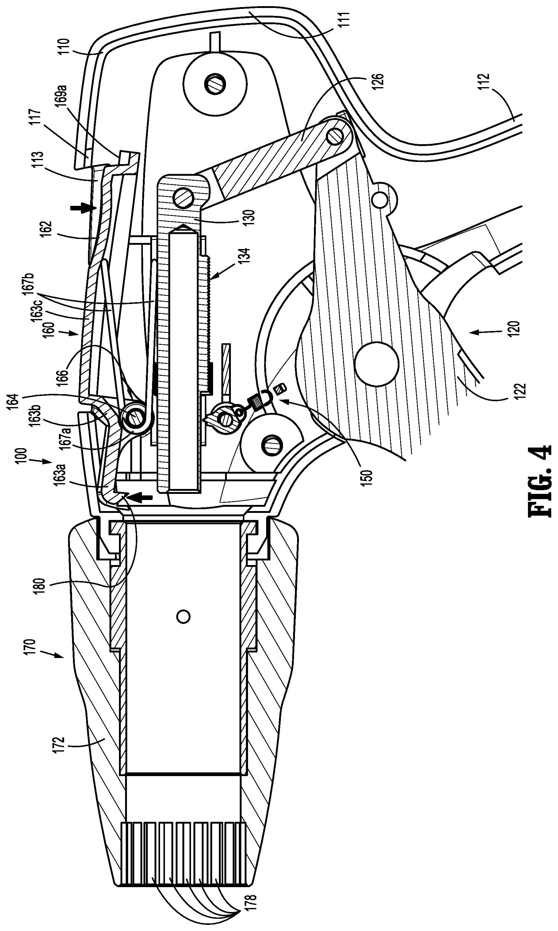
[0023] FIG. 4 is a longitudinal, cross-sectional view of the proximal portion of the endoscopic surgical clip applier of FIG. 1 illustrating the handle assembly after disengagement and withdrawal of the elongated assembly therefrom;
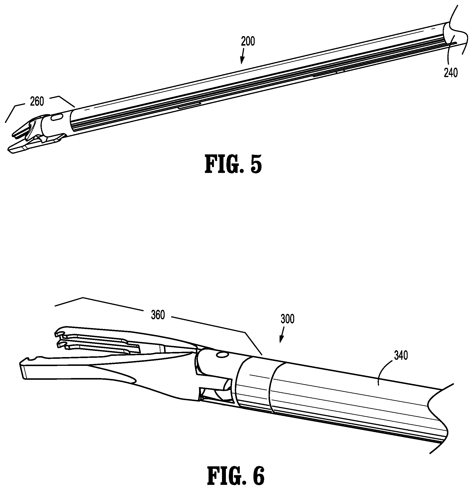
[0024] FIG. 5 is a perspective view of a distal portion of the elongated assembly of the endoscopic surgical clip applier of FIG. 1;
[0025] FIG. 6 is a perspective view of a distal portion of another elongated assembly configured for use with the endoscopic surgical clip applier of FIG. 1;
[0026] FIG. 7 is an enlarged, perspective view, with portions shown transparent, of a portion of the endoscopic surgical clip applier of FIG. 1, illustrating engagement of the elongated assembly with the handle assembly via a lever of a latch assembly of the handle assembly;
[0027] FIG. 8 is a top view of a portion of the endoscopic surgical clip applier of FIG. 1, illustrating the lever of the latch assembly of the handle assembly positioned relative to a housing of the handle assembly;
[0028] FIG. 9 is a side, perspective view of the lever of FIG. 7;
[0029] FIG. 10 is an enlarged, side, perspective view of the area of detail indicated as "10" in FIG. 9; and
[0030] FIG. 11 is an enlarged end view of a proximal portion of the lever of FIG. 7.
DETAILED DESCRIPTION
[0031] The present disclosure provides latch assemblies for surgical instruments and surgical instruments including the same. Although detailed herein as incorporated into a surgical clip applier, the latch assemblies of the present disclosure may alternatively be incorporated into any suitable surgical instrument.
[0032] Turning to FIGS. 1-4, an endoscopic surgical clip applier embodying the aspects and features of the present disclosure is shown generally identified by reference numeral 10. Surgical clip applier 10 generally includes a handle assembly 100 and a plurality of elongated assemblies 200 (FIGS. 1-5), 300 (FIG. 6) selectively connectable to handle assembly 100. Handle assembly 100 is configured to operate each of the plurality of elongated assemblies 200, 300 upon connection thereto, and may be configured as a sterilizable, reusable component such that handle assembly 100 may be repeatedly used with different and/or additional elongated assemblies 200, 300 during the course of one or more surgical procedures. The elongated assemblies 200, 300 may be configured as single-use disposable components, limited-use disposable components, or reusable components, depending upon a particular purpose and/or the configuration of the particular elongated assembly. In either configuration, the need for multiple handle assemblies 100 is obviated and, instead, the surgeon need only select an appropriate elongated assembly 200, 300 and connect that elongated assembly to handle assembly 100 in preparation for use.
[0033] Handle assembly 100 generally includes a housing 110, an actuation mechanism 120 operably associated with housing 110, a ratchet mechanism 150 operably disposed within housing 110, and a rotation knob assembly 170 operably coupled to a distal portion of housing 110. A latch assembly 160, provided in accordance with the present disclosure, is also operably associated with housing 110, as detailed below. Housing 110 supports and/or encloses the operating components of handle assembly 100. Actuation mechanism 120 is configured to enable selective firing of one or more surgical clips (not shown) from the end effector of the attached elongated assembly. Ratchet mechanical 150 enables ratcheting advancement of drive bar 130 of actuation mechanism 120, when an elongated assembly configured for ratcheting actuation is connected to handle assembly 100. Latch assembly 160 is configured to facilitate releasable locking engagement of the elongated assembly with handle assembly 100. Rotation knob assembly 170 enables the selective rotation of the attached elongated assembly relative to housing 110.
[0034] With additional reference to FIGS. 5 and 6, as noted above, handle assembly 100 is configured for use with different elongated assemblies such as, for example, elongated assembly 200 (FIG. 5) and elongated assembly 300 (FIG. 6). Handle assembly 100, more specifically, is configured for both ratcheting use, e.g., in connection with elongated assembly 200 (FIG. 5), and non-ratcheting use, e.g., in connection with elongated assembly 300 (FIG. 6). Elongated assemblies 200, 300 are described briefly below. A more detailed discussion of elongated assemblies, e.g., elongated assemblies 200, 300, configured for use with handle assembly 100 can be found in International Patent Application Publication No. WO/2018/035796, filed on Aug. 26, 2016, International Patent Application Publication No. WO/2017/124217, filed on Jan. 18, 2016, and/or International Patent Application Publication No. WO/2017/059587, filed on Oct. 10, 2015, the entire content of each of which is hereby incorporated herein by reference.
[0035] Referring to FIGS. 1-5, elongated assembly 200 is configured for ratcheting use and generally includes a proximal hub 220, an elongated shaft 240 extending distally from proximal hub 220, an end effector assembly 260 disposed towards a distal end portion of elongated shaft 240, and an inner drive assembly (not shown) operably coupled between handle assembly 100 and end effector assembly 260 when elongated assembly 200 is engaged with handle assembly 100 to enable the sequential firing of at least one surgical clip (not shown) about tissue. End effector assembly 260 of elongated assembly 200 may be configured to fire surgical clips similar to those shown and described in U.S. Pat. Nos. 7,819,886 or 7,905,890, the entire content of each of which is hereby incorporated herein by reference.
[0036] Proximal hub 220 of elongated assembly 200 defines a plurality of indexing protrusions 222 annularly disposed thereabout towards a distal end portion thereof (see FIG. 4). Indexing protrusions 222 are configured for slidable receipt within longitudinally-extending grooves 178 defined within outer knob 172 of rotation knob assembly 170 to rotationally fix proximal hub 220 of elongated assembly 200 relative to rotation knob assembly 170 upon insertion of proximal hub 220 therethrough. As such, in use, rotation of outer knob 172 of rotation knob assembly 170 relative to housing 110 effects corresponding rotation of elongated assembly 200 relative to housing 110.
[0037] Proximal hub 220 further defines an annular channel 224 towards the proximal end thereof and a chamfered proximal edge 226. As detailed below, upon insertion of proximal hub 220 through rotation knob assembly 170 and into body portion 111 of housing 110, chamfered proximal edge 226 cams engagement tooth 180 of lever 162 of latch assembly 160 over the outer surface of proximal hub 220 until engagement tooth 180 is disposed in alignment with annular channel 224, whereby engagement tooth 180 falls into engagement within annular recess 224 to engage proximal hub 220 and, thus, elongated assembly 200, with handle assembly 100.
[0038] Referring to FIG. 6, elongated assembly 300 is configured for non-ratcheting use and generally includes a proximal hub (not shown), an elongated shaft 340 extending distally from the proximal hub, an end effector assembly 360 disposed towards a distal end portion of elongated shaft 340, and an inner drive assembly (not shown) operably coupled between handle assembly 100 and end effector assembly 360 when elongated assembly 300 is engaged with handle assembly 100 (FIG. 1) to enable grasping and/or manipulation of tissue, retrieval of a surgical clip, and firing of the surgical clip about tissue. It is contemplated that end effector assembly 360 of elongated assembly 300 may be configured to fire surgical clips similar to those shown and described in U.S. Pat. No. 4,834,096, the entire contents of which are hereby incorporated herein by reference.
[0039] With additional reference to FIGS. 1-4, the proximal hub (not shown) of elongated assembly 300, similarly as with proximal hub 220 of elongated assembly 200, may also include indexing protrusions to rotationally fix elongated assembly 300 relative to rotation knob assembly 170 upon insertion of the proximal hub therethrough and/or an annular channel and chamfered proximal edge to facilitate engagement of engagement tooth 180 of lever 162 of latch assembly 160 with elongated assembly 300 to engage elongated assembly with handle assembly 100.
[0040] Although exemplary elongated assemblies 200, 300 configured for ratcheting and non-ratcheting use, respectively, are detailed above, it is contemplated that various other elongated assemblies for performing various different surgical tasks and/or having various different configurations suitable for ratcheting or non-ratcheting use may likewise be utilized with handle assembly 100.
[0041] Turning back to FIGS. 1-4, housing 110 of handle assembly 100 may be formed from first and second housing halves 110a, 110b (FIG. 8) that cooperate to define a body portion 111 and a fixed handle portion 112 depending from body portion 111. Body portion 111 of housing 110 includes an internal pivot post 114 extending transversely within body portion 111, and a distal nose 116 defining a distal opening 118 therethrough. A proximal end portion of a proximal hub of an elongated assembly, e.g., proximal hub 220 of elongated assembly 200 or the proximal hub (not shown) of elongated assembly 300 (FIG. 6), is configured to extend at least partially through distal opening 118 of distal nose 116 of housing 110 when the elongated assembly is engaged with handle assembly 100.
[0042] Actuation mechanism 120 is operably supported by housing 110 and includes a trigger 122, a linkage 126, a drive bar 130, and a biasing member 140. Trigger 122 includes a grasping portion 123, an intermediate pivot portion 124, and a proximal extension 125. Grasping portion 123 of trigger 122 extends downwardly from body portion 111 of housing 110 in opposed relation relative to fixed handle portion 112 of housing 110. Grasping portion 123 is configured to facilitate grasping and manipulation of trigger 122. Intermediate pivot portion 124 of trigger 122 is at least partially disposed within housing 110 and defines a pivot aperture configured to receive pivot post 114 of housing 110 so as to enable pivoting of trigger 122 about pivot post 114 and relative to housing 110, e.g., between an un-actuated position, wherein grasping portion 123 of trigger 122 is spaced-apart relative to fixed handle portion 112, and an actuated position, wherein grasping portion 123 of trigger 122 is approximated relative to fixed handle portion 112.
[0043] Proximal extension 125 of trigger 122 is disposed on an opposite side of intermediate pivot portion 124 and, thus, pivot post 114, as compared to grasping portion 123 of trigger 122. As such, pivoting of grasping portion 123 to rotate in one direction, e.g., proximally towards fixed handle portion 112, pivots proximal extension 125 to rotate in the opposite direction, e.g., distally. Proximal extension 125 of trigger 122 is pivotably coupled to the proximal end of linkage 126. Biasing member 140 is secured at either end and extends between proximal extension portion 125 of trigger 122 and a support (not shown) disposed within fixed handle portion 112 of housing 110. Pivoting of grasping portion 123 towards the actuated position elongates biasing member 140 storing energy therein such that, upon release of grasping portion 123, grasping portion 123 is returned towards the un-actuated position under the bias of biasing member 140. Although illustrated as an extension coil spring, biasing member 140 may define any suitable configuration for biasing grasping portion 123 of trigger 122 towards the unactuated position.
[0044] As noted above, linkage 126 is coupled at its proximal end to proximal extension portion 125 of trigger 122. Linkage 126 is also pivotably coupled at its distal end to a proximal end of drive bar 130. As a result of this configuration, pivoting of grasping portion 123 of trigger 122 towards the actuated position urges proximal extension portion 125 of trigger 122 distally which, in turn, urges linkage 126 distally to, in turn, urge drive bar 130 distally.
[0045] Drive bar 130 is slidable through body portion 111 of housing 110, in response to actuation of trigger 122, to urge a distal end portion 132 of drive bar 130 into contact with a proximal actuator of an inner drive assembly (not shown) of an elongated assembly, e.g., elongated assembly 200 or elongated assembly 300 (FIG. 6), engaged with handle assembly 100 to fire a surgical clip supported at the end effector assembly of the elongated assembly. Drive bar 130, more specifically, is slidable from an un-actuated, proximal position, corresponding to the un-actuated position of grasping portion 123 of trigger 122, to an actuated, distal position, corresponding to the actuated position of grasping portion 123 of trigger 122, in order to urge the proximal actuator of the inner drive assembly (not shown) of the elongated assembly distally to fire a surgical clip supported at the end effector assembly of the elongated assembly.
[0046] Drive bar 130 may further include a ratchet rack 134 extending along at least a portion of an underside surface thereof. Ratchet rack 134 is configured to selectively interface with ratchet mechanism 150 to enable advancement of drive bar 130 in either a ratcheting condition or a non-ratcheting condition. Ratchet rack 134 and ratchet mechanism 150 may be configured similarly as described in, for example, International Patent Application Publication No. WO/2018/035796 or International Patent Application Publication No. WO/2017/124217, each of which was previously incorporated by reference herein.
[0047] Continuing with reference to FIGS. 1-4, rotation knob assembly 170 is rotatably coupled to distal nose 116 of body portion 111 of housing 110 and is configured to receive the proximal hub of the elongated assembly, e.g., proximal hub 220 of elongated assembly 200, coupled to handle assembly 100 in fixed rotational engagement therewith, e.g., via receipt of indexing protrusions 222 within grooves 178 (see FIGS. 2 and 4), to enable selective rotation of elongated assembly 200 relative to housing 110 upon rotation of outer knob 172 of rotation knob assembly 170 relative to housing 110.
[0048] Referring now to FIGS. 1-4, 7, and 8, latch assembly 160 of the present disclosure includes a lever 162, a pivot pin 164, and a biasing member 166. Lever 162 is at least partially disposed within a cut-out 113 defined without housing 110 of handle assembly 100 to enable manual manipulation thereof. Cut-out 113, more specifically, is formed via cooperation of first and second cut-out portions 113a, 113b defined within the first and second housing halves 110a, 110b, respectively, that cooperate to define housing 110 (see FIG. 8).
[0049] With additional reference to FIG. 9, lever 162 defines a distal engagement section 163a, an intermediate section 163b, and a proximal manipulatable section 163c. Distal engagement section 163a of lever 162 includes an engagement tooth 180 extending therefrom. Engagement tooth 180 is configured to engage an elongated assembly, e.g., elongated assembly 200, inserted into handle assembly 100. More specifically, as noted above with respect to elongated assembly 200, for example, upon insertion of proximal hub 220 of elongated assembly 200 into handle assembly 100, engagement tooth 180 is configured to cam over chamfered proximal edge 226 of proximal hub 220 and into engagement within annular channel 224 to thereby lock elongated assembly 200 in engagement with handle assembly 100.
[0050] With particular reference to FIG. 7, pivot pin 164 of latch assembly 160 pivotably couples intermediate section 163b of lever 162 with housing 110 of handle assembly 100 such that urging of proximal manipulation section 163c of lever 162 in a first direction into housing 110 (towards a disengaged position of lever 162), urges distal engagement section 163a of lever 162 in a second, opposite direction out of engagement with annular channel 224 of proximal hub 220 of elongated assembly 200. Biasing member 166 is configured as a torsion spring having a body 167a disposed about pivot pin 164 and first and second legs 167b disposed between housing 110 and proximal manipulation section 163c of lever 162 to bias proximal manipulation section 163c of lever 162 away from housing 110 towards an engaged position of lever 162, thereby biasing distal engagement section 163a towards an engaged position. However, other suitable configurations of biasing member 166 are also contemplated.
[0051] Referring to FIGS. 7-11, in conjunction with FIGS. 1-4, proximal manipulation section 163c of lever 162 is selectively depressible into cut-out 113 of housing 110, as illustrated in FIGS. 3 and 4, against the bias of biasing member 166, to urge distal engagement section 163a from an engaged position (FIGS. 1 and 2; the engaged position of lever 162) towards a disengaged position (FIGS. 3 and 4; the disengaged position of lever 162) to disengage engagement tooth 180 from annular channel 224 of proximal hub 220 of elongated assembly 200 and enable withdrawal of elongated assembly 200 from handle assembly 100.
[0052] Proximal manipulation section 163c of lever 162, more specifically, includes an exterior surface 168a, a side wall 168b depending from exterior surface 168a in generally perpendicular orientation relative thereto and disposed about at least a portion of the outer periphery thereof, and a lip 168c extending from a free end of side wall 168b (opposite the end of side wall 168b attached to exterior surface 168a) in generally perpendicular orientation relative to side wall 168b so as to define a shelf 168d extending outwardly from side wall 168b. Shelf 168d extends along the lateral sides and about the proximal end of side wall 168b. Intermediate section 163b of lever 162 extends distally from the free end of side wall 168b at the distal end of side wall 168b. "Generally," as used above, takes into account material and manufacturing tolerances.
[0053] As illustrated in FIGS. 1, 7, and 8, exterior surface 168a of proximal manipulation section 163c of lever 162, in the engaged position of lever 162, is substantially complementary to and configured to substantially fully occupy cut-out 113 of housing 110. "Substantially," as utilized above, accounts for manufacturing and material tolerances of housing halves 110a, 110b and lever 162, which may result in exterior surface 168a not fully occupying and/or not being exactly complementary to cut-out 113 of housing 110. In fact, in order to ensure that exterior surface 168a is not too large for cut-out 113 (or that cut-out 113 is not too small for exterior surface 168a), which would render these components incompatible and, thus, unusable, lever 162 and/or housing halves 110a, 110b are manufactured taking into account the tolerances thereof such that, even at the greatest tolerance variation(s), exterior surface 168a is able to fit within cut-out 113. As a result, it will often be the case that exterior surface 168a does not fully occupy and/or is not exactly complementary to cut-out 113 of housing 110.
[0054] In embodiments, housing halves 110a, 110b are formed from a polymeric material via injection molding, while lever 162 is formed from a metal via metal injection molding (MIM), although other materials and/or manufacturing methods are also contemplated. The tolerance considerations detailed above are particularly relevant where different materials and/or manufacturing methods are utilized, and/or where less-precise manufacturing methods are utilized, to ensure that tolerances do not "stack up" to render components incompatible with one another.
[0055] Continuing with reference to FIGS. 1, 7, and 8, exterior surface 168a of proximal manipulation section 163c of lever 162, in the engaged position of lever 162, is further configured to substantially conform to the outer surface profile of housing 110 surrounding cut-out 113 so as to minimize variations along the exterior surface of housing 110 and exterior surface 168a of proximal manipulation section 163c of lever 162. Exterior surface 168a may additionally define a dimple 168e configured to receive a user's finger to facilitate depression of proximal manipulation section 163c of lever 162 from the engaged position to the disengaged position.
[0056] Referring also to FIG. 9, shelf 168d of proximal manipulation section 163c of lever 162, defined by lip 168c thereof, in the engaged position of lever 162, is configured to abut or sit in close proximity to an interior surface of housing 110 along the lateral sides and about the proximal end of cut-out 113. More specifically, shelf 168d is configured to extend outwardly from side wall 168b and, thus, from exterior surface 168a, a sufficient distance so as to extend beyond cut-out 113 and at least partially overlap the interior surface of housing 110. As such, shelf 168d covers any gap defined between exterior surface 168a of proximal manipulation section 163c of lever 162 and housing 110, thus inhibiting visualization into the interior of housing 110 (rather, only shelf 168d would be visible at any gap). As can be appreciated, the particular width of shelf 168d is determined at least in part on the tolerance variations noted above, such that, regardless of the particular tolerance variations, shelf 168d sufficiently covers any gap defined between exterior surface 168a of proximal manipulation section 163c of lever 162 and housing 110. In addition to accounting for tolerance variations, shelf 168d also serves to cover any gap defined between exterior surface 168a of proximal manipulation section 163c of lever 162 and housing 110 as a result of lateral and/or longitudinal shifting of proximal manipulation section 163c of lever 162 relative to housing 110.
[0057] With reference to FIGS. 7, 10, and 11, a proximal stop 169a is disposed on shelf 168d of proximal manipulation section 163c of lever 162 at a proximal end of proximal manipulation section 163c and extends therefrom towards exterior surface 168a of proximal manipulation section 163c. Proximal stop 169a includes a stop surface 169b and angled guide surfaces 169c disposed on either side of stop surface 169b and angled inwardly towards one another, thus defining a wedge-shaped configuration of proximal stop 169a.
[0058] Proximal stop 169a serves as a positive stop to proximal manipulation section 163c of lever 162 to inhibit lever 162 from moving beyond the engaged position. More specifically, in the engaged position of lever 162, stop surface 169b of proximal stop 169a abuts a corresponding surface of a receiving portion 117 of the interior surface of housing 110 (see FIGS. 2, 4, 7, and 8) disposed proximally adjacent cut-out 113 to inhibit further travel of lever 162 under the bias of biasing member 166.
[0059] Proximal stop 169a also serves as a centering feature, wherein, upon movement of lever 162 towards the engaged position with proximal manipulation section 163c in an off-centered position relative to cut-out 113, one of the angled guide surfaces 169c of proximal stop 169a (depending upon which direction proximal manipulation section 163c of lever 162 is offset relative to cut-out 113) contacts a corresponding and complementary guide surface of receiving portion 117 (see FIGS. 2, 4, 7, and 8) of the interior surface of housing 110 to cam proximal manipulation section 163c of lever 162 into alignment with cut-out 113 such that, upon reaching the engaged position, proximal manipulation section 163c of lever 162 is centered relative to cut-out 113.
[0060] With general reference to FIGS. 1-4 and 7, insertion and engagement of an elongated assembly, e.g., elongated assembly 200, with handle assembly 100 and use of the same are described. In order to engage elongated assembly 200 with handle assembly 100, proximal hub 220 of elongated assembly 200 is inserted through outer knob 172 of rotation knob assembly 170 and into distal nose 116 of housing 110, wherein engagement tooth 180 of latch assembly 160 cams over chamfered proximal edge 226 of proximal hub 220 and into engagement within annular channel 224 of proximal hub 220 to thereby rotatably engage proximal hub 220 relative to housing 110. Upon insertion of proximal hub 220 through rotation knob assembly 170, indexing protrusions 222 of proximal hub 220 are received within longitudinally-extending grooves 178 of outer knob 172 to rotationally fix proximal hub 220 relative to outer knob 172.
[0061] With elongated assembly 200 engaged with handle assembly 100 as detailed above, handle assembly 100 may be manipulated and/or outer knob 172 rotated to position end effector 260 (FIG. 5) of elongated assembly 200 about tissue to be treated. Once end effector 260 is positioned as desired, trigger 122 is pivoted towards fixed handle portion 112 of housing 110 to urge linkage 126 distally which, in turn, urges drive bar 130 distally through housing 110 to drive the inner drive assembly (not shown) of elongated assembly 200 distally through elongated assembly 200 to fire and form a surgical clip from end effector assembly 260 (FIG. 5) about tissue. The above may be repeated to fire and form several surgical clips about tissue, as necessary.
[0062] In order to disengage elongated assembly 200 from handle assembly 100, e.g., for cleaning and/or sterilization, or to replace elongated assembly 200 with another elongated assembly, proximal manipulation section 163c of lever 162 of latch assembly 160 is depressed inwardly into housing 110 to disengage engagement tooth 180 from annular channel 224, thereby disengaging lever 162 from proximal hub 220 of elongated assembly 200 and enabling proximal hub 220 to be withdrawn distally from housing 110 and rotation knob assembly 170.
[0063] It should be understood that the foregoing description is only illustrative of the present disclosure. Various alternatives and modifications can be devised by those skilled in the art without departing from the disclosure. Accordingly, the present disclosure is intended to embrace all such alternatives, modifications and variances. The embodiments described with reference to the attached drawing figures are presented only to demonstrate certain examples of the disclosure. Other elements, steps, methods and techniques that are insubstantially different from those described above and/or in the appended claims are also intended to be within the scope of the disclosure.
* * * * *
D00000
D00001
D00002
D00003
D00004
D00005
D00006
D00007
XML
uspto.report is an independent third-party trademark research tool that is not affiliated, endorsed, or sponsored by the United States Patent and Trademark Office (USPTO) or any other governmental organization. The information provided by uspto.report is based on publicly available data at the time of writing and is intended for informational purposes only.
While we strive to provide accurate and up-to-date information, we do not guarantee the accuracy, completeness, reliability, or suitability of the information displayed on this site. The use of this site is at your own risk. Any reliance you place on such information is therefore strictly at your own risk.
All official trademark data, including owner information, should be verified by visiting the official USPTO website at www.uspto.gov. This site is not intended to replace professional legal advice and should not be used as a substitute for consulting with a legal professional who is knowledgeable about trademark law.