Linkage Assembly For Reusable Surgical Handle Assemblies
Zammataro; Thomas A. ; et al.
U.S. patent application number 16/433109 was filed with the patent office on 2020-02-13 for linkage assembly for reusable surgical handle assemblies. The applicant listed for this patent is Covidien LP. Invention is credited to Jacob C. Baril, Brian J. Creston, Thomas A. Zammataro.
| Application Number | 20200046328 16/433109 |
| Document ID | / |
| Family ID | 69406983 |
| Filed Date | 2020-02-13 |


| United States Patent Application | 20200046328 |
| Kind Code | A1 |
| Zammataro; Thomas A. ; et al. | February 13, 2020 |
LINKAGE ASSEMBLY FOR REUSABLE SURGICAL HANDLE ASSEMBLIES
Abstract
A handle assembly for actuating an end effector is provided. The handle assembly includes an actuation mechanism with a linkage assembly configured to maximize the output force. The linkage assembly includes first, second, and third linkage members operably disposed between a trigger and a drive member.
| Inventors: | Zammataro; Thomas A.; (Hamden, CT) ; Creston; Brian J.; (West Haven, CT) ; Baril; Jacob C.; (Norwalk, CT) | ||||||||||
| Applicant: |
|
||||||||||
|---|---|---|---|---|---|---|---|---|---|---|---|
| Family ID: | 69406983 | ||||||||||
| Appl. No.: | 16/433109 | ||||||||||
| Filed: | June 6, 2019 |
Related U.S. Patent Documents
| Application Number | Filing Date | Patent Number | ||
|---|---|---|---|---|
| 62718027 | Aug 13, 2018 | |||
| Current U.S. Class: | 1/1 |
| Current CPC Class: | A61B 2017/0046 20130101; A61B 17/00 20130101; A61B 17/1285 20130101; A61B 2017/2922 20130101; A61B 2017/00367 20130101; A61B 2017/0042 20130101 |
| International Class: | A61B 17/00 20060101 A61B017/00 |
Claims
1. A handle assembly, comprising: a housing defining a longitudinal axis; a trigger operably coupled to the housing and movable to cause actuation of the handle assembly; a drive member movable within the housing from an initial position to an advanced position in response to actuation of the trigger; and a linkage assembly operably disposed between the trigger and the drive member to move the drive member from the initial position to the advanced position, the linkage assembly including first, second, and third linkage members, the first linkage member being pivotally secured to the trigger on a first end and to first ends of the second and third linkage members on a second end, the second linkage member being pivotally secured to the drive member on a second end, and the third linkage member being pivotally secured to the housing on a second end.
2. The handle assembly of claim 1, wherein the first and third linkage members each include a pair of linkage members.
3. The handle assembly of claim 1, wherein a first end of the first linkage member is pivotally secured to the trigger by a first pivot pin.
4. The handle assembly of claim 3, wherein the housing defines a track and the first pivot pin extends within the track.
5. The handle assembly of claim 1, wherein the housing includes a body portion and a trigger portion.
6. The handle assembly of claim 1, further including a friction reducing mechanism operably disposed within the housing relative to the drive member.
7. The handle assembly of claim 6, wherein the friction reducing mechanism includes first and second bearing assemblies, each of the bearing assemblies including a sleeve rotatably disposed within the housing and configured to facilitate movement of the drive member.
8. The handle assembly of claim 7, wherein the first bearing assembly is positioned such that a longitudinal axis of the second linkage member is tangent to the first bearing sleeve when the linkage assembly is in an initial condition.
9. The handle assembly of claim 8, wherein the second bearing assembly is positioned such that the longitudinal axis of the second linkage member is tangent to the second bearing sleeve when the linkage assembly is in a fully-actuated condition.
10. The handle assembly of claim 7, wherein the first bearing assembly includes a first pivot pin and the second bearing assembly includes a second pivot pin, the first and second bearing sleeves being rotatably supported about the respective first and second pivot pins.
11. The handle assembly of claim 6, wherein the housing includes a pivot post and the friction reducing mechanism includes a bearing sleeve, the bearing sleeve being received about the pivot post between the pivot post and the trigger to reduce friction between the housing and the trigger during actuation of the handle assembly.
12. The handle assembly of claim 1, wherein the second and third linkage members define a first angle therebetween when the drive member is in the initial position.
13. The handle assembly of claim 12, wherein the first angle is less than ninety degrees.
14. The handle assembly of claim 13, wherein the second and third linkage members define a second angle therebetween when the drive member is in the advanced position.
15. The handle assembly of claim 14, wherein the second angle is greater than ninety degrees.
16. The handle assembly of claim 1, further including a feedback mechanism disposed within the housing to indicate when the drive member attains the advanced position.
Description
CROSS-REFERENCE TO RELATED APPLICATION
[0001] This application claims the benefit of and priority to U.S. Provisional Patent Application No. 62/718,027 filed Aug. 13, 2018, the entire disclosure of which is incorporated by reference herein.
BACKGROUND
Technical Field
[0002] The present disclosure relates to handle assemblies for surgical instruments. More particularly, the present disclosure relates to linkage assemblies for reusable surgical handle assemblies.
Description of Related Art
[0003] Reusable handle assemblies are known in the medical art and are used for a number of distinct and useful surgical procedures. In the case of a laparoscopic surgical procedure, access to the interior of an abdomen is achieved through narrow tubes or cannulas that are releasably secured to the reusable handles inserted through a small entrance incision in the skin. Minimally invasive procedures performed elsewhere in the body are often generally referred to as endoscopic procedures.
[0004] Generally, handle assemblies are configured to translate a rotational input force into a linear output force. It would be beneficial to have a handle assembly that includes a linkage assembly that translates a rotational input force into a linear output force necessary for performing a procedure, while maximizing a mechanical advantage of the linkage assembly.
SUMMARY
[0005] A handle assembly for actuating an end effector is provided. According to an aspect of the present disclosure, the handle assembly includes a housing defining a longitudinal axis; a trigger operably coupled to the housing and movable to cause actuation of the handle assembly; a drive member movable within the housing from an initial position to an advanced position in response to actuation of the trigger; and a linkage assembly operably disposed between the trigger and the drive member to move the drive member from the initial position to the advanced position. The linkage assembly including first, second, and third linkage members, the first linkage member being pivotally secured to the trigger on a first end and to first ends of the second and third linkage members on a second end, the second linkage member being pivotally secured to the drive member on a second end, and the third linkage member being pivotally secured to the housing on a second end.
[0006] The first and third linkage members each may include a pair of linkage members.
[0007] A first end of the first linkage member may be pivotally secured to the trigger by a first pivot pin.
[0008] The housing may define a track and the first pivot pin extends within the track.
[0009] The housing may include a body portion and a trigger portion.
[0010] The handle assembly may further include a friction reducing mechanism operably disposed within the housing relative to the drive member.
[0011] The friction reducing mechanism may include first and second bearing assemblies, each of the bearing assemblies including a sleeve rotatably disposed within the housing and configured to facilitate movement of the drive member.
[0012] The first bearing assembly may be positioned such that a longitudinal axis of the second linkage member is tangent to the first bearing sleeve when the linkage assembly is in an initial condition.
[0013] The second bearing assembly may be positioned such that the longitudinal axis of the second linkage member is tangent to the second bearing sleeve when the linkage assembly is in a fully-actuated condition.
[0014] The first bearing assembly may include a first pivot pin and the second bearing assembly includes a second pivot pin, the first and second bearing sleeves being rotatably supported about the respective first and second pivot pins.
[0015] The housing may include a pivot post and the friction reducing mechanism includes a bearing sleeve, the bearing sleeve being received about the pivot post between the pivot post and the trigger to reduce friction between the housing and the trigger during actuation of the handle assembly.
[0016] The second and third linkage members may define a first angle therebetween when the drive member is in the initial position. The first angle may be less than ninety degrees.
[0017] The second and third linkage members may define a second angle therebetween when the drive member is in the advanced position. The second angle may be greater than ninety degrees.
[0018] The handle assembly may further include a feedback mechanism disposed within the housing to indicate when the drive member attains the advanced position.
BRIEF DESCRIPTION OF THE DRAWINGS
[0019] Aspects and features of the present disclosure are described in detail with reference to the drawing figures wherein like reference numerals identify similar or identical structural elements and:
[0020] FIG. 1 is a front, perspective view of a surgical instrument according to an embodiment of the present disclosure including a handle assembly having an elongated assembly engaged therewith;
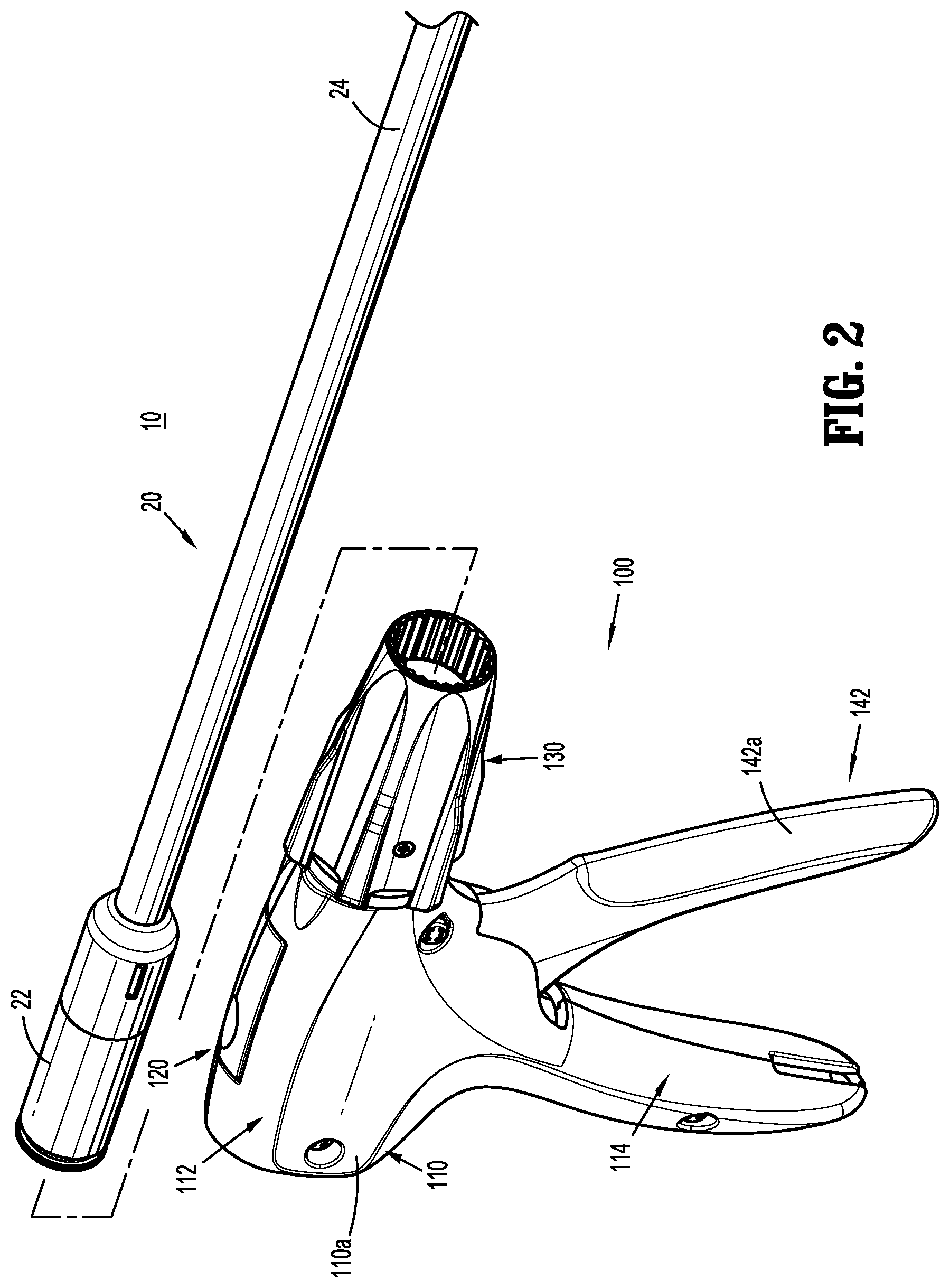
[0021] FIG. 2 is front perspective view of the surgical instrument with the elongated assembly removed from the handle assembly;
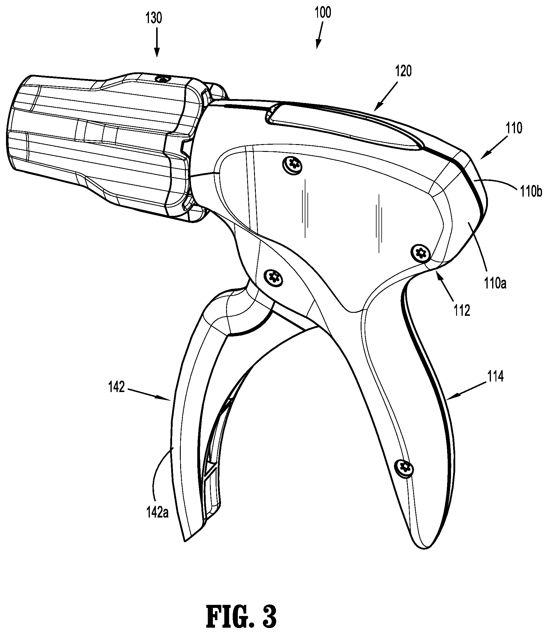
[0022] FIG. 3 is a back perspective view of the handle assembly of the surgical instrument shown in FIGS. 1 and 2;
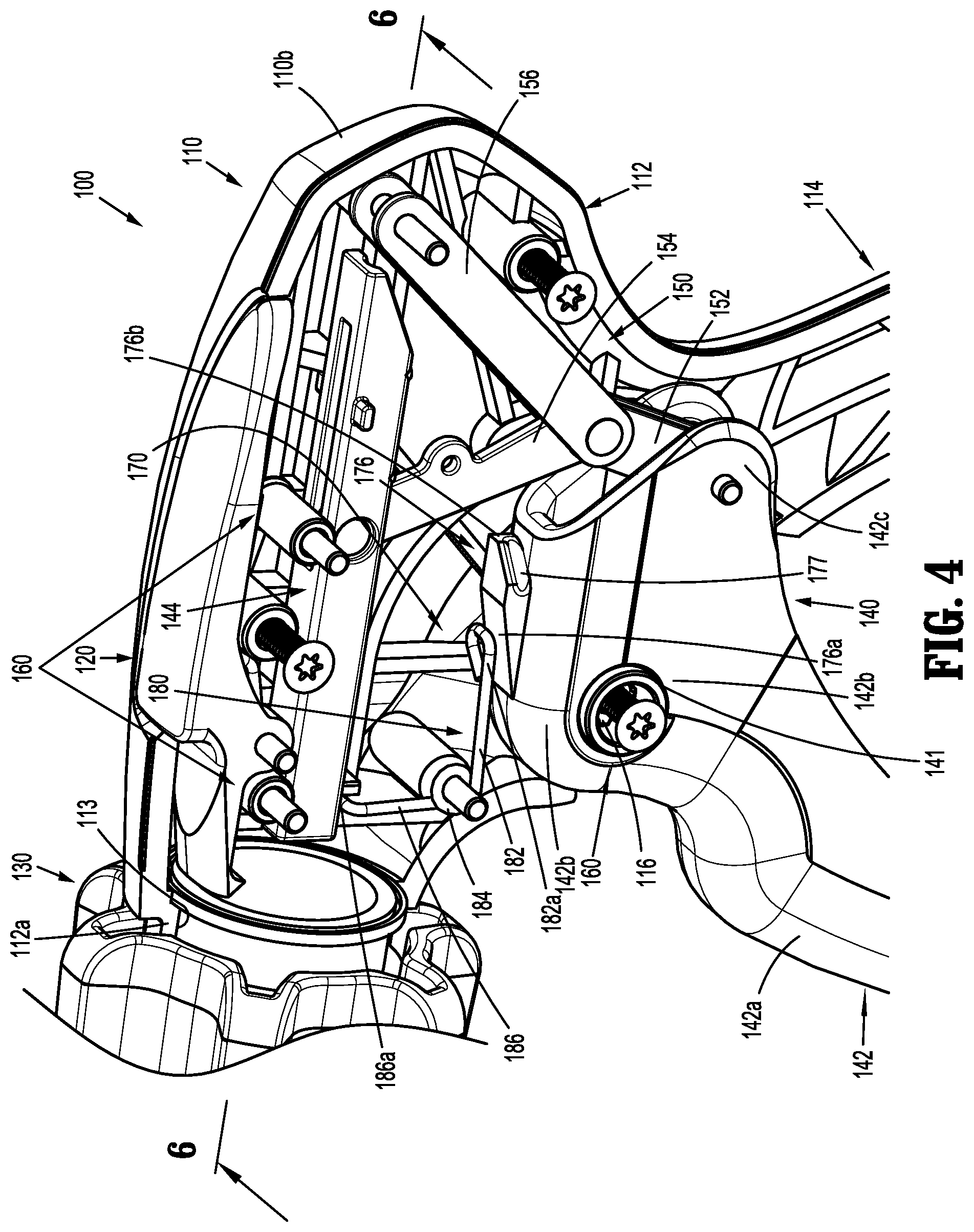
[0023] FIG. 4 is a side perspective view of the handle assembly of the surgical instrument shown in FIGS. 1 and 2, with a housing half removed exposing an actuation assembly including a trigger and a linkage assembly;
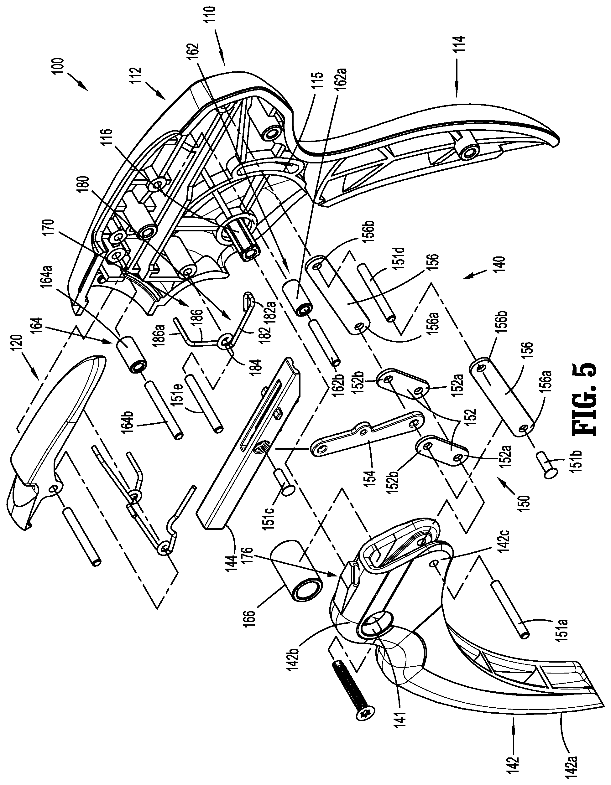
[0024] FIG. 5 is an exploded view of the handle assembly shown in FIG. 4;
[0025] FIG. 6 is a cross-sectional side view taken along line 6-6 shown in FIG. 4;
[0026] FIG. 7 is a side view of the handle assembly shown in FIG. 4, with the actuation mechanism in an initial position;
[0027] FIG. 8 is a side view of the handle assembly shown in FIG. 4, with the actuation mechanism in a partially advanced position; and
[0028] FIG. 9 is a side view of the handle assembly shown in FIG. 4, with the actuation mechanism in an advanced position.
DETAILED DESCRIPTION
[0029] As detailed herein and shown in the drawing figures, as is traditional when referring to relative positioning on a surgical instrument, the term "proximal" refers to the end of the apparatus or component thereof which is closer to the user and the term "distal" refers to the end of the apparatus or component thereof which is farther away from the user. Further, to the extent consistent, any or all of the aspects and features detailed herein may be used in conjunction with any or all of the other aspects and features detailed herein.
[0030] The present disclosure provides a linkage assembly for handle assemblies of surgical instruments. Although detailed herein as incorporated into handle assemblies for surgical instruments, such as clip appliers, the linkage assembly of the present disclosure may be incorporated into any suitable surgical instrument.
[0031] Turning to FIGS. 1 and 2, a surgical instrument according to aspects of the present disclosure is shown generally as surgical instrument 10. The surgical instrument 10 generally includes a handle assembly 100 and an adapter assembly 20 selectively connectable to the handle assembly 100. The handle assembly 100 is configured to operate the adapter assembly 20 upon connection of the adapter assembly 20 to the handle assembly 100, and may be configured as a sterilizable, reusable component such that handle assembly 100 may be repeatedly used with different and/or additional elongated assemblies (not shown) during the course of one or more surgical procedures. The adapter assembly 20 may be configured as a single-use disposable component, limited-use disposable components, or reusable components, depending upon a particular purpose and/or the configuration of the particular adapter assembly. In either configuration, the need for multiple handle assemblies 100 is obviated and, instead, the surgeon need only select an appropriate adapter assembly, and connect that adapter assembly to the handle assembly 100 in preparation for use.
[0032] With additional reference to FIGS. 3 and 4, the handle assembly 100 includes a housing 110, a latch assembly 120 (FIG. 3) operably disposed within housing 110, a rotation knob assembly 130 disposed on a distal end of the housing 110, and an actuation mechanism 140 operably disposed within the housing 110. The housing 110 supports and/or encloses the operating components of handle assembly 100. The latch mechanism 120 is configured to facilitate releasable locking engagement of the adapter assembly 20 with the handle assembly 100. The rotation knob assembly 130 enables the selective rotation of the attached adapter assembly 20 relative to the housing 110. The actuation mechanism 140 is configured to enable selective firing of one or more fasteners (e.g., surgical clips, not shown) from an end effector (not shown) of the attached adapter assembly 20.
[0033] The handle assembly 100 will only be described to the extent necessary to fully disclose the aspects of the present disclosure. For a detailed description of the operation and function of an exemplary handle assembly, including exemplary latch and rotation knob assemblies, please refer to commonly owned U.S. Prov. Pat. App. Ser. No. 62/581,144 ("the '144 application"), filed Nov. 3, 2017, the content of which is incorporated herein by reference in its entirety. Other exemplary embodiments of handle assemblies may be found in commonly owned Intl. Pat. App. Nos. PCT/CN2016/096666 and PCT/CN2016/071178, filed on Aug. 26, 2016 and Jan. 18, 2016, respectively, the content of each is hereby incorporated herein by reference in their entireties.
[0034] With continued reference to FIGS. 1 and 2, the adapter assembly 20 of the surgical instrument 10 generally includes a proximal hub 22, an elongated shaft 24 extending distally from the proximal hub 22, an end effector (not shown) disposed towards a distal end portion of the elongated shaft 24, and an inner drive assembly (not shown) operably coupled between the handle assembly 100 and the end effector when adapter assembly 20 is engaged with the handle assembly 100, to enable the sequential firing of at least one surgical clip (not shown) about tissue. The end effector of the adapter assembly 20 may be configured to fire surgical clips similar to those shown and described in U.S. Pat. Nos. 7,819,886 or 7,905,890, the contents of each of which are hereby incorporated herein by reference in their entirety.
[0035] With additional reference to FIGS. 3 and 4, the housing 110 of the handle assembly 100 may be formed from first and second housing halves 110a, 110b that cooperate to define a body portion 112 and a fixed handle portion 114 depending from the body portion 112. The body portion 112 of the housing 110 includes a distal nose 112a (FIG. 4) defining a distal opening 113 (FIG. 3) therethrough. A proximal end portion of the proximal hub 22 of the adapter assembly 20 is configured to extend at least partially through the distal opening 113 of the distal nose 112a of the housing 110 when the adapter assembly 20 is engaged with the handle assembly 100. The body portion 112 of housing 110 includes a pivot post 116 (FIG. 5) extending transversely within body portion 112.
[0036] The actuation mechanism 140 is operably supported by the housing 110 and includes a trigger member 142, a drive member or plunger 144 operably connected to the drive member 144 by a linkage assembly 150, friction reducing mechanisms 160, and a feedback mechanism 170. The friction reducing mechanisms 160 reduce the friction in the handle assembly 100, e.g., between the pivot post 116 and the trigger member 142 and/or between the drive member 144 and the housing 110, thereby providing a smoother firing sequence and a better mechanical advantage.
[0037] With particular reference to FIG. 4, the trigger member 142 of the actuation mechanism 140 includes a grasping portion 142a, an intermediate pivot portion 142b, and a proximal extension 142c.
[0038] The grasping portion 142a of the trigger member 142 extends downwardly from the body portion 112 of the housing 110 in opposed relation relative to the fixed handle portion 114 of the housing 110. The grasping portion 142a is configured to facilitate grasping and manipulation of the trigger member 142.
[0039] The intermediate pivot portion 142b of the trigger member 142 is at least partially disposed within the housing 110. The intermediate pivot portion 142b defines a pivot aperture 141 configured to receive a third bearing member 166 of the friction reducing mechanisms 160 and the pivot post 116 of the housing 110 received through the third bearing member 166. The third bearing member 166 enables smoother pivoting with less wear of the trigger member 142 about the pivot post 116 and relative to the housing 110 between an initial or pre-actuated position (FIG. 6) and an actuated position (FIG. 9). The grasping portion 142a of the trigger member 142 is spaced-apart from the fixed handle portion 114 when the trigger member 142 is in the initial position, and the grasping portion 142a of the trigger member 142 is approximated to the fixed handle portion 114 as the trigger member 142 is pivoted to the actuated position (FIG. 9).
[0040] The proximal extension 142c of the trigger member 142 is disposed on an opposite side of the intermediate pivot portion 142b of the trigger member 142 and, thus, opposite the pivot post 116, as compared to the grasping portion 142a of the trigger member 142. As such, pivoting of the grasping portion 142a to rotate in a first direction, e.g., proximally towards the fixed handle portion 114, pivots the proximal extension 142c to rotate in a second, opposite direction, e.g., distally.
[0041] With addition reference to FIG. 5, the linkage assembly 150 includes a first linkage member or trigger link 152, a second linkage member or plunger link 154, and a third linkage member or fixed link 156. In embodiments, and as shown, the first and third linkage members 152, 156 each include a pair of linkage members 152, 156, although either or both may include only a single linkage member. The first linkage members 152 are pivotally coupled to the proximal extension 142c of the trigger member 142 at first ends 152a of the first linkage members 152 by a first pivot pin 151a. The first pivot pin 151a extends into a track 115 defined in the body portion 112 of the housing 110. The track 115 guides the pivoting of the trigger member 142 during actuation of the handle assembly 100.
[0042] The second and third linkage members 154, 156 are each pivotally coupled to second ends 152b of the first linkage member 152 at first ends 154a, 156a of the respective second and third linkages 154, 156 by a second pivot pin 151b. A second end 154b of the second linkage member 154 is pivotally coupled to the drive member 144 by a third pivot pin 151c, while second ends 156b of the third linkage members 156 are pivotally coupled to the body portion 112 of the housing 110 by a fourth pivot pin 151d. The pivot point between the first linkage members 152 and the proximal extension 142c of the trigger member 142, the pivot point between the first linkage members 152 and second and third linkage members 164, 166, and the pivot point between the second linkage member 154 and the drive member 144 are movable pivot points (e.g., movable relative to the housing 110), while the pivot point between the third linkage member 156 and the housing 110 is a fixed pivot point (e.g., fixed relative to the housing 110).
[0043] With reference to FIG. 6, when the linkage assembly 150 of the actuation mechanism 140 is in a first or initial position, the second and third linkage members 154, 156 of the linkage assembly 150 define an angle ".alpha." therebetween less than ninety degrees (90.degree.). The angle ".alpha." is determined to maximize the mechanical advantage of the linkage assembly 150.
[0044] With reference to FIGS. 8 and 9, upon actuation of the trigger member 142, e.g., proximal pivoting of the grasping portion 142a of the trigger member 142, as indicated by arrow "A", the proximal extension 142c of the trigger member 142 is moved in a counter-clockwise direction, thereby urging the first linkage member 152 towards the drive member 144. This movement of the first linkage member 152 towards the drive member 144, in turn, urges the first ends 154a, 156a of the second and third linkage members 154, 156, respectively, towards the drive member 144, as indicated by arrow "C" in FIG. 8, to, in turn, urge the second end 154b of the second linkage member 154 distally such that the drive member 144 is translated distally through the body portion 112 of the housing 110, as indicated by arrow "D" shown in FIG. 8. A biasing spring (not shown) may be provided to bias the trigger member 142 towards an initial or pre-actuated position, thereby biasing the drive member 144 proximally.
[0045] The drive member 144 of the actuation mechanism 140 is slidably disposed within the body portion 112 of the housing 110 in longitudinal alignment with the adapter assembly 20 when the adapter assembly 20 is engaged with the handle assembly 100. Distal sliding of the drive member 144 through the body portion 112 of the housing 110 during the firing stroke of the handle assembly 100 urges the drive member 144 into contact with a proximal portion (not shown) of inner drive sleeve (not shown) of the elongate assembly 20 to translate the inner drive sleeve distally, e.g., to apply, form or close a surgical fastener or clip supported on an end effector (not shown). In embodiments, a stroke of the drive member 144 is one inch (1'') in length.
[0046] With continued reference to FIG. 9, when the actuation mechanism 140 is in a fully-actuated position, the second and third linkage members 154, 156 define an angle ".beta." therebetween greater than ninety degrees (90.degree.). The angle ".beta." is determined to maximize the mechanical advantage of the linkage assembly 150.
[0047] In embodiments, the linkage assembly 150 provides a firing stroke necessary for performing a given function while maximizing an output force. The linkage assembly 150 is designed so a mechanical advantage (and therefore output force) increases smoothly throughout the firing stroke, allowing a user to input a same amount of force while the linkage assembly 150 creates a greater output force at an end of the firing stroke.
[0048] With reference back to FIG. 6, the friction reducing mechanisms 160 of the actuation mechanism 140 include first and second sleeve bearing assemblies 162, 164, and the third sleeve bearing 166. The first and second sleeve bearing assemblies 162, 164 include respective first and second sleeve bearings 162a, 164a supported by respective first and second bearing pins 162b, 164b within the body portion 112 of the housing 110. The first and second bearing assemblies 162, 164 of the friction reducing mechanism 160 facilitate distal movement of the drive member 144. More particularly, the first and second sleeve bearings 162a, 164a are rotatably supported about the respective first and second bearing pins 162b, 164b and are positioned to engage the drive member 144. As the drive member 144 slides in a distal direction, the first and second sleeve bearings 162a, 164a rotate about the respective first and second bearing pins 162b, 164b thereby reducing the friction between the body portion 112 of the housing 110 and the drive member 144.
[0049] In embodiments, the first sleeve bearing assembly 162 is positioned to facilitate initial movement of the linkage assembly 150. More particularly, the first sleeve bearing assembly 162 is positioned such that an initial force output from the second linkage member 154, as indicated by arrow "E" shown in FIG. 7, is tangent to the first sleeve bearing 162a. In this manner, the position of the first sleeve bearing assembly 162 facilitates initial rolling of the first sleeve bearing 162a. The second sleeve bearing assembly 164 is positioned such that a force output from the second linkage member 154, as indicated by arrow "F" shown in FIG. 9, is tangent to the second sleeve bearing 164a at the end of the firing cycle. The first sleeve bearing assembly 162 experiences a higher load at the beginning of the firing stroke and the second bearing assembly 164 experiences a higher load at the end of the firing stroke.
[0050] In embodiments, the first and second sleeve bearings 162, 164 are formed of polyether ether ketone (PEEK), nylon, other polymers, metal, or other suitable material.
[0051] Although shown as having only the first and second sleeve bearing assemblies 162, 164 supporting the drive member 144, it is envisioned that the friction reducing mechanism 160 may include more than two sleeve bearing (not shown).
[0052] As noted above, the third sleeve bearing 166 of the friction reducing mechanism is received about the pivot post 116 of the body portion 112 of the housing 110. The intermediate pivot portion 142b of the trigger member 142 of the actuation mechanism 140 defines the pivot aperture 141 that receives the pivot post 116 of the housing 110. The third sleeve bearing 166 of the friction reducing mechanism 160 is disposed within the pivot aperture 141 in the trigger member 142 such that the third sleeve bearing 166 is positioned between the pivot post 116 of the body portion 112 and the trigger member 142.
[0053] In embodiments, the third sleeve bearing 166 is fixed relative to the pivot post 116 such that the trigger member 142 of the actuation mechanism 140 rotates relative to the third bearing sleeve 166 and the pivot post 116. In other embodiments, the third bearing sleeve 166 is fixed relative to the trigger member 142 such that the trigger member 142 and the third sleeve bearing 166 rotate relative to the pivot post 116. In yet other embodiments, the third sleeve bearing 166 is neither fixed relative to the pivot post 116 nor fixed relative to the trigger member 142. In this manner, the third sleeve bearing 166 rotates relative to either or both of the pivot post 116 and the trigger member 142.
[0054] In embodiments, the third sleeve bearing 166 is formed of stainless steel, PEEK, or other suitable material. The third sleeve bearing 166 reduces friction between the trigger member 142 and the body portion 112 of the housing 110, thereby reducing wear in the handle assembly 100.
[0055] The actuation mechanism 140 further includes the feedback mechanism 170 for signal, e.g., audible or tactile, completion of a firing stroke. As described below, the feedback mechanism 170 produces an audible and/or or tactile feedback during actuation of the handle assembly 100 upon completion of an actuation stroke, e.g., full clip formation.
[0056] With particular reference to FIG. 4, the feedback mechanism 170 is operably disposed within the body portion 112 of the housing 110 of the handle assembly 100 and includes a ramp portion 176 and a torsion spring 180. More particularly, the ramp portion 176 is formed on an outer surface of the intermediate pivot portion 142b of the trigger member 142 of the actuation mechanism 140. The ramp portion 176 includes an inclined surface 176a and an edge surface 176b, and defines a cam track 177. As will be detailed below, during a firing stroke of the handle assembly 100, the ramp portion 176 directs a hammer portion 182a of the torsion spring 180 into a snapping engagement with an outer surface of the intermediate pivot portion 142b of the trigger member 142 to provide an audible and/or tactile response that the handle assembly 100 firing stroke is complete, e.g., the actuation mechanism 140 is fully actuated. The ramp portion 176 is configured to reset the hammer portion 182a of the torsion spring 180 as the trigger member 142 returns to its pre-actuated position to permit subsequent firing of the handle assembly 100.
[0057] The torsion spring 180 includes an elongate body 182 with the hammer portion 182a disposed on a first, free end and a spring portion 184 on a second end. A flange portion 186 extends from the spring portion 184 and includes an engagement portion 186a formed on a free end of the flange portion 186.
[0058] The spring portion 184 of the torsion spring 180 of the feedback mechanism 170 is received by a fifth pivot pin 151e that is supported within the body portion 112 of the housing 110. The elongate portion 182 of the torsion spring 180 extends towards the intermediate pivot portion 142b of the trigger member 142 such that the hammer portion 182a of the torsion spring 180 engages the inclined portion 176a of the ramp portion 176 of the feedback mechanism 170. The engagement portion 186a of the torsion spring 180 engages the body portion 112 of the housing 110 and remains in a fixed position.
[0059] With particular reference to FIG. 8, upon actuation of the trigger member 142, e.g., proximal pivoting of the grasping portion 142a of the trigger member 142 toward the fixed handle portion 114 of the housing 110, as indicated by arrow "A", the intermediate pivot portion 242b of the trigger member 142 moves in a counter-clockwise direction, as indicated by arrow "B". The counter-clockwise movement of the intermediate pivot portion 142b of the trigger member 142 causes the hammer portion 182a on the free end of the elongate body 182 of the torsion spring 180 to ride along the inclined surface 176a of the ramp portion 176 of the feedback mechanism 170, as indicated by arrow "G" shown in FIG. 8.
[0060] During actuation of the trigger member 142, the engagement portion 186a on the free end of the flange portion 186 of the torsion spring 180 remains in a fixed position. The movement of the hammer portion 182a of the torsion spring 180 along the inclined surface 176a of the ramp portion 176 cams the spring portion 184 of the torsion spring 180 to a loaded condition.
[0061] Turning to FIG. 9, the ramp portion 176 and the torsion spring 180 of the feedback mechanism 170 are configured such that at the end of the actuation stroke, the hammer portion 182a of the torsion spring 180 disengages from the edge surface 176b of the ramp portion 176. As noted above, during actuation of the trigger member 142, the spring portion 184 is cammed to the loaded condition. In this manner, when the hammer portion 182a of the torsion spring 180 disengages from the edge surface 176b of the ramp 176, the hammer portion 182a snaps against the outer surface of the intermediate pivot portion 142b of the trigger member 142, as indicated by arrow "H", thereby producing an audible response. It is envisioned that the contact of the hammer portion 182a of the torsion spring 180 may also produce a tactile response, e.g., vibration.
[0062] As the trigger member 142 returns to its initial position, the elongate body 182 of the torsion spring 180 advances relative to the ramp portion 176 such that the hammer portion 182a of the torsion spring 180 engages the cam track 167 of the ramp portion 176. As the hammer portion 182a engages the cam track 167 of the ramp portion 176, the hammer portion 182a is guided around the ramp portion 176 to return to the hammer portion 182a to its initial position disposed along the inclined surface 176a of the ramp portion 176, thereby resetting the feedback mechanism 170, and readying the handle assembly 100 for further use.
[0063] It should be understood that the foregoing description is only illustrative of the present disclosure. Various alternatives and modifications can be devised by those skilled in the art without departing from the disclosure. Accordingly, the present disclosure is intended to embrace all such alternatives, modifications and variances. The embodiments described with reference to the attached drawing figures are presented only to demonstrate certain examples of the disclosure. Other elements, steps, methods and techniques that are insubstantially different from those described above and/or in the appended claims are also intended to be within the scope of the disclosure.
* * * * *
D00000
D00001
D00002
D00003
D00004
D00005
D00006
D00007
D00008
XML
uspto.report is an independent third-party trademark research tool that is not affiliated, endorsed, or sponsored by the United States Patent and Trademark Office (USPTO) or any other governmental organization. The information provided by uspto.report is based on publicly available data at the time of writing and is intended for informational purposes only.
While we strive to provide accurate and up-to-date information, we do not guarantee the accuracy, completeness, reliability, or suitability of the information displayed on this site. The use of this site is at your own risk. Any reliance you place on such information is therefore strictly at your own risk.
All official trademark data, including owner information, should be verified by visiting the official USPTO website at www.uspto.gov. This site is not intended to replace professional legal advice and should not be used as a substitute for consulting with a legal professional who is knowledgeable about trademark law.