Endoscope Having An Additional External Working Channel
HO; Chi-Nghia ; et al.
U.S. patent application number 16/603392 was filed with the patent office on 2020-02-13 for endoscope having an additional external working channel. The applicant listed for this patent is Ovesco Endoscopy AG. Invention is credited to Chi-Nghia HO, Alexander MEINING.
| Application Number | 20200046201 16/603392 |
| Document ID | / |
| Family ID | 62046865 |
| Filed Date | 2020-02-13 |


| United States Patent Application | 20200046201 |
| Kind Code | A1 |
| HO; Chi-Nghia ; et al. | February 13, 2020 |
ENDOSCOPE HAVING AN ADDITIONAL EXTERNAL WORKING CHANNEL
Abstract
A working channel device is mountable on the outer circumference of an endoscope, such as an endoscope of the flexible shaft design. The device has a tubular or hose-like working channel and a distal fixing element that can be fixed to the working channel. The distal fixing element can engage around the endoscope in a clamping manner at the endoscope head of the endoscope. A proximal fixing element can be fixed to the working channel, which can engage around the endoscope, preferably at the endoscope grip of the endoscope. A preferably sleeve-like adapter can be mounted at the proximal end of the working channel of the working channel device. The adapter has or forms the proximal fixing element and additionally forms a connection point/interface for the connection of medical devices.
| Inventors: | HO; Chi-Nghia; (Reutlingen, DE) ; MEINING; Alexander; (Ulm, DE) | ||||||||||
| Applicant: |
|
||||||||||
|---|---|---|---|---|---|---|---|---|---|---|---|
| Family ID: | 62046865 | ||||||||||
| Appl. No.: | 16/603392 | ||||||||||
| Filed: | April 6, 2018 | ||||||||||
| PCT Filed: | April 6, 2018 | ||||||||||
| PCT NO: | PCT/EP2018/058874 | ||||||||||
| 371 Date: | October 7, 2019 |
| Current U.S. Class: | 1/1 |
| Current CPC Class: | A61B 1/00135 20130101; A61B 2017/00296 20130101; A61B 1/0014 20130101; A61B 1/005 20130101; A61B 2090/034 20160201; A61B 1/00128 20130101 |
| International Class: | A61B 1/00 20060101 A61B001/00; A61B 1/005 20060101 A61B001/005 |
Foreign Application Data
| Date | Code | Application Number |
|---|---|---|
| Apr 7, 2017 | DE | 10 2017 107 546.1 |
Claims
1. A working channel device for mounting on an outer circumference of an endoscope comprising: a tube-shaped or hose-shaped working channel, a distal fixing means, which is configured to grip around the endoscope, in a clamping or clasping manner, a proximal fixing means, which is configured to grip around the endoscope, in a clamping or clasping manner, and an adapter which is mounted or mountable on a proximal end region of the working channel of the working channel device, which has or integrally forms the proximal fixing means and which additionally forms a connection point/interface for connecting medical devices.
2. The working channel device according to claim 1, wherein the distal fixing means forms at least one endoscope-head stop which defines the distal fixing mean in a form-fit manner in an axial direction with respect to the endoscope head.
3. The working channel device according to claim 2, wherein the endoscope-head stop is configured such that it abuts against a front side of an endoscope head of an endoscope adapted with the working channel device.
4. The working channel device according to claim 3, wherein the distal fixing means has a first accommodation with at least partial circular cross-section for accommodation of the working channel and a second accommodation with at least partial circular cross-section being adjacent to the first accommodation and aligned in parallel for accommodation of the endoscope head.
5. The working channel device according to claim 4, wherein the first accommodation has a sleeve shape open or slotted towards the second accommodation and the second accommodation is formed by two crescent-shaped clamping arms extending away from the first accommodation.
6. The working channel device according to claim 5, wherein the crescent-shaped clamping arms of the distal fixing means define a circular shape with their outer surfaces in a plane of a front surface of an adapted endoscope and the outer surface of the sleeve defining the first accommodation protrudes beyond this circular shape in the radial direction by no more than half the diameter of the first accommodation.
7. The working channel device according to claim 1, wherein the proximal fixing means is configured as two wings or lugs extending away from the adapter for gripping around the endoscope grip, which in turn, in particular in the region of the free ends of the wings or lugs, each form an eyelet for guiding a tape or strap.
8. The working channel device according to claim 7, further comprising a hook arranged on the side of the sleeve-shaped adapter remote from the wings or lugs for guiding a tape or strap.
9. The working channel device according to claim 1, wherein the proximal fixing means comprises two bow-shaped cantilevers which are configured to accommodate the endoscope grip in a clamping manner between them, by their elasticity.
10. The working channel device according to claim 9, wherein at least one of the bow-shaped cantilevers has, at its free end, a hook, curved in the opposite direction to the direction of curvature of the cantilever, for holding a tape or strap.
11. The working channel device according to claim 9, wherein at least one of the bow-shaped cantilevers has at least one retaining slit in its edge area, which is narrowed in an area of a slot opening in order to securely hold a tape or strap.
12. The working channel device according to claim 1, wherein the adapter has an integrated valve which prevents foreign bodies from entering the proximal end of the working channel and/or air or liquid from leaking from the proximal end of the working channel.
13. The working channel device according to claim 1, further comprising an additional cover hose adapted and configured to be pulled over the working channel and the endoscope adapted therewith.
14. An endoscope system comprising an endoscope with a flexible endoscope shaft, at the distal end of which an endoscope head is arranged and at the proximal end of which an endoscope grip is arranged, the endoscope system comprising a working channel device according to claim 1.
Description
CROSS-REFERENCE TO RELATED APPLICATIONS
[0001] This application is the United States national phase entry of International Application No. PCT/EP2018/058874, filed Apr. 6, 2018, which claims the benefit of priority of German Application No. 10 2017 107 546.1, filed Apr. 7, 2017. The contents of International Application No. PCT/EP2018/058874 and German Application No. 10 2017 107 546.1 are incorporated by reference herein in their entireties.
FIELD
[0002] The invention relates to an adaptive, external/separate working channel device for optional mounting on the outer circumference of an endoscope, in particular of the flexible shaft design, and an endoscope of the (flexible) shaft design with such an external working channel (Additional Working Channel, AWC for short). The AWC is prepared to be mounted on/around an endoscope/endoscope head and to be aligned to it in any desired or predefined position.
SUMMARY
[0003] The AWC according to the invention essentially has four components. [0004] A first component is realized by a distal end cap or clamp/spring clip, which (regarding its inner diameter) is designed to establish a plug/snap-on or clip connection with the distal end (endoscope head) of the (common/conventional) endoscope. Apart from the snap-on connection, the end cap or clamp/spring clip can preferably additionally be fixed with an adhesive tape, which is selectively either firmly connected to the end cap or clamp/spring clip or is enclosed as a separate additional component. [0005] A second component is realized by a hose or a flexible pipe sleeve, which forms the additional working channel and which can be connected to or is fixedly connected to the end cap or clamp/spring clip. The hose/pipe sleeve is preferably cut at the distal end, or is or can be cut to length according to the current axial length of the endoscope shaft. In addition, further attachment positions/mounting means, e.g. for additional adhesive strips or clips or Velcro tapes, may be present/provided at the hose/pipe sleeve, preferably at even distances, by means of which the hose can be fixed to the endoscope shaft between the endoscope head and its endoscope grip provided as standard. [0006] A third component relates to a releasable fixing means for the temporary/optional mounting of the proximal end portion of the separate hose/pipe sleeve on the endoscope grip, for example consisting of two clip-type or wing-type mounting lugs which can be mounted on the proximal end portion of the hose/pipe sleeve (after having been correctly cut to length) and have fastenings (eyelets/through holes/hooks/buttons and the like) at their free ends to which preferably a tension strap such as Velcro tape/rubber strap/belt, etc. can be fastened. [0007] A fourth component is realized by an adapter, which has an interface for standardized connection systems. This adapter is initially prepared to be attached in a sleeve-like manner to the proximal end of the hose/pipe sleeve, whereby the adapter also simultaneously carries the two clamp-like or wing-like mounting lugs, preferably integrally. Thus, conventional connection systems can also be coupled with the adapter in order to economically couple the AWC with other medical devices such as syringes/pumps, etc.
[0008] In other words, the invention relates to a retrofit kit for equipping an endoscope with an additional working channel (AWC). The set includes said additional working channel, which is formed as a flexible hose and is arranged and attached circumferentially at the shaft of the retrofitted endoscope; a distal fixing means, which is configured to connect the distal end of the additional working channel to the distal end of a retrofitted endoscope; a proximal fixing means, which is configured to fix the proximal end of the additional working channel to the handle portion of a retrofitted endoscope; and an adapter as an interface for medical instruments or devices, e.g. syringes.
[0009] According to one aspect of the invention, a cover hose may be provided as an additional (fifth) component which is adapted and configured to be pulled over the working channel and the endoscope adapted/retrofitted with it. The cover hose thus envelops the endoscope and the additional working channel arranged on it and can thus prevent tissue from being trapped between these two components, which can lead to complications (e.g. tearing of tissue and perforation).
[0010] According to a preferred configuration of the invention, the distal fixing means can form at least one endoscope-head stop, which fixes the distal fixing means with respect to the endoscope head by a form closure in its axial direction. This endoscope-head stop can preferably be configured in such a way that it contacts a front side/front surface of the endoscope head of an endoscope adapted with the working channel device. In this way, a form-fit is created that reliably prevents the additional working channel from slipping proximally when an endoscope retrofitted with the AWC is inserted.
[0011] According to a further preferred configuration, the distal fixing means may have a first accommodation with at least partial circular cross-section for accommodation of the working channel and a second accommodation adjacent to the first accommodation, aligned in parallel, with at least partial circular cross-section for accommodation of the endoscope head.
[0012] According to a preferred configuration of the invention, the first accommodation may have a sleeve shape open or slotted towards the second accommodation and the second accommodation may be formed by two crescent-shaped clamping arms extending away from the first accommodation. The distal end of the additional working channel can be correspondingly pushed into the sleeve-shaped first accommodation, while the crescent-shaped clamping arms with their inner surfaces form the second accommodation, which can clamp around a distal tip of a retrofitted endoscope. Due to its slotted sleeve shape, the first accommodation can serve by means of its inherent elasticity as a spring element to provide (at least part of) the clamping force of the clamping arms.
[0013] According to a further development of the above configuration, the crescent-shaped clamping arms of the distal fixing means can with their outer surfaces define a circular shape in a plane of a front surface of an adapted endoscope and the outer surface of the sleeve defining the first accommodation can project/protrude in the radial direction by no more than half the diameter of the first accommodation over this circular shape. In other words, the additional working channel can fit into the frontal silhouette of the distal fixing means. In contrast to conventional AWCs, in which the distal working channel end protrudes radially with its entire diameter from the outer circumference of the distal cap, the described constructive design results in better gliding properties when inserting a retrofitted endoscope.
[0014] According to a preferred configuration, the proximal fixing means can be integrally formed with the adapter. The adapter accordingly has two clamp-like, bow-like, or wing-like mounting lugs or cantilevers (preferably made of one piece of material), which serve to attach the adapter ergonomically to the grip of the endoscope. The cantilevers have holes in a first configuration and the adapter has a hook or button, all of which serve to engage a Velcro tape connection or other (tensioning) strap. In a second, alternative configuration, the cantilevers have hooks (hook-shaped extensions or buckles), which serve to snap or insert the endoscope grip into the hook-shaped extensions or buckles and additionally enable an additional elastic element/strap/tape/rubber to be hooked in, in order to be able to firmly clamp the handle.
[0015] According to a preferred configuration of the invention, the clamp-like, bow-like or wing-like mounting lugs or cantilevers can form at their free ends hooks facing away from each other, which can be tensioned against each other with a rubber ring or band to secure the mounting lugs or cantilevers enclosing the endoscope grip. Preferably, at least one of the mounting lugs or one of the cantilevers may have a retaining slit at its edge area adjacent to the hook at its free end. This retaining slit is open towards the edge of the mounting lug or cantilever, wherein this opening forms a narrow point (bottleneck). The rubber ring or rubber band is snapped (can be pre-mounted therein) through said narrow point and is thus held in the retaining slit. This prevents the rubber ring or rubber band from slipping out of the hooks and falling to the ground (becoming unsterile) when mounting the AWC to the endoscope grip.
[0016] According to a further aspect, the adapter may have an integrated valve or a valve may be mounted on the adapter which is intended to seal the working channel when an instrument is used in the working channel and/or to seal in such a way that no air/liquid can escape/flow from the patient's body.
BRIEF DESCRIPTION OF THE DRAWING FIGURES
[0017] The invention is explained in more detail in the following with reference to the accompanying figures using preferred exemplary embodiments. The figures are merely schematic in nature and serve exclusively to understand the invention. The same elements are provided with the same reference signs. They show:
[0018] FIG. 1 shows an endoscope comprising an endoscope grip, an endoscope shaft as well as a working channel device according to a first configuration of the present invention;
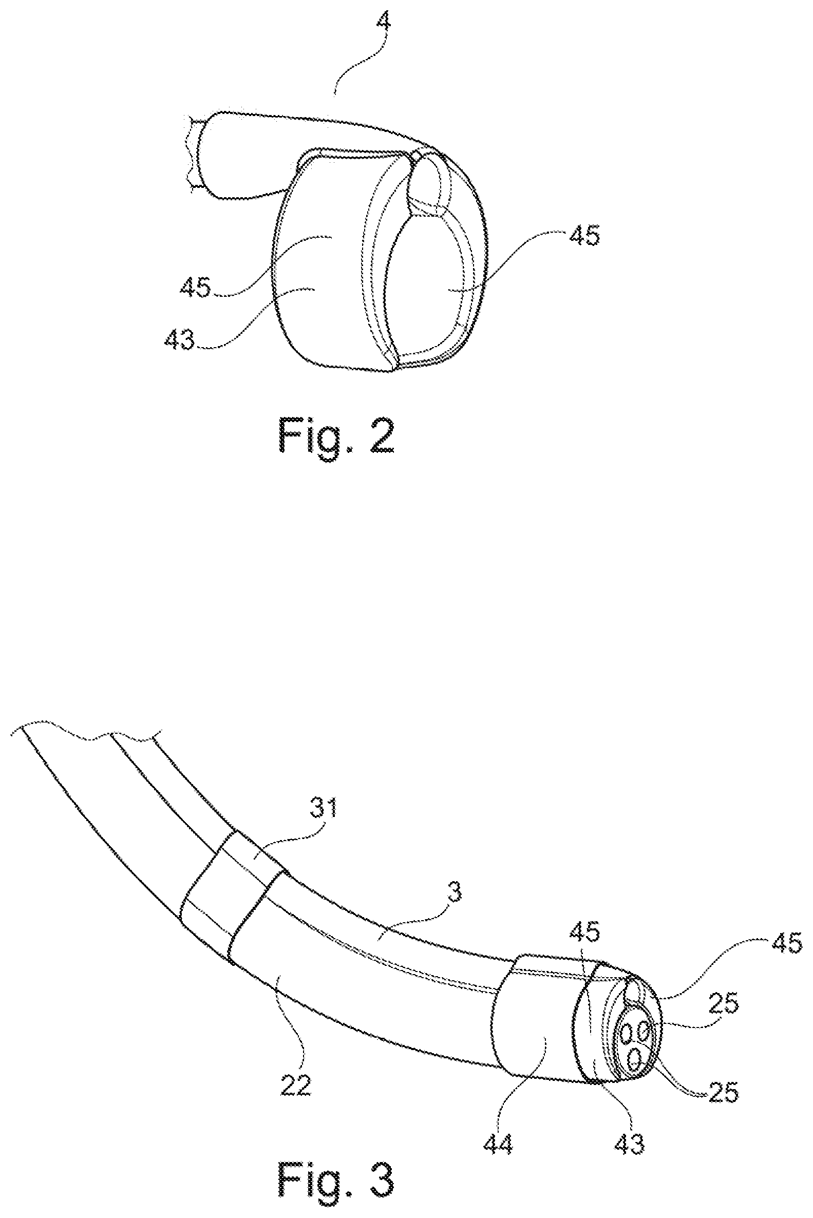
[0019] FIG. 2 shows a distal fixing means or a distal end cap of a working channel device according to the invention according to the first configuration;
[0020] FIG. 3 shows a tube-shaped or hose-shaped working channel with the distal end cap according to the first configuration in a state mounted on an endoscope;
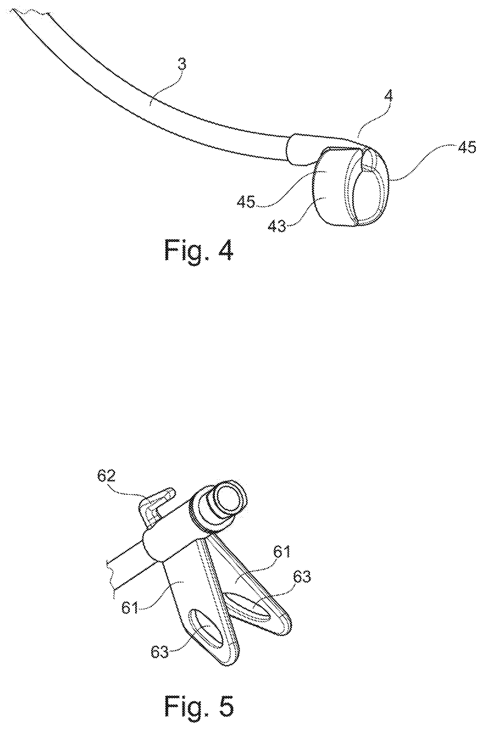
[0021] FIG. 4 shows the tube-shaped or hose-shaped working channel with the distal end cap according to the first configuration without endoscope;
[0022] FIG. 5 shows a proximal fixing means of the working channel device according to the first configuration;
[0023] FIG. 6 shows the proximal fixing means of the working channel device according to the first configuration in a state when it is fixed to an endoscope grip;
[0024] FIG. 7 shows a proximal fixing means of a working channel device according to a second configuration;
[0025] FIG. 8 shows a sectional view of the proximal fixing means of the working channel device according to the second configuration;
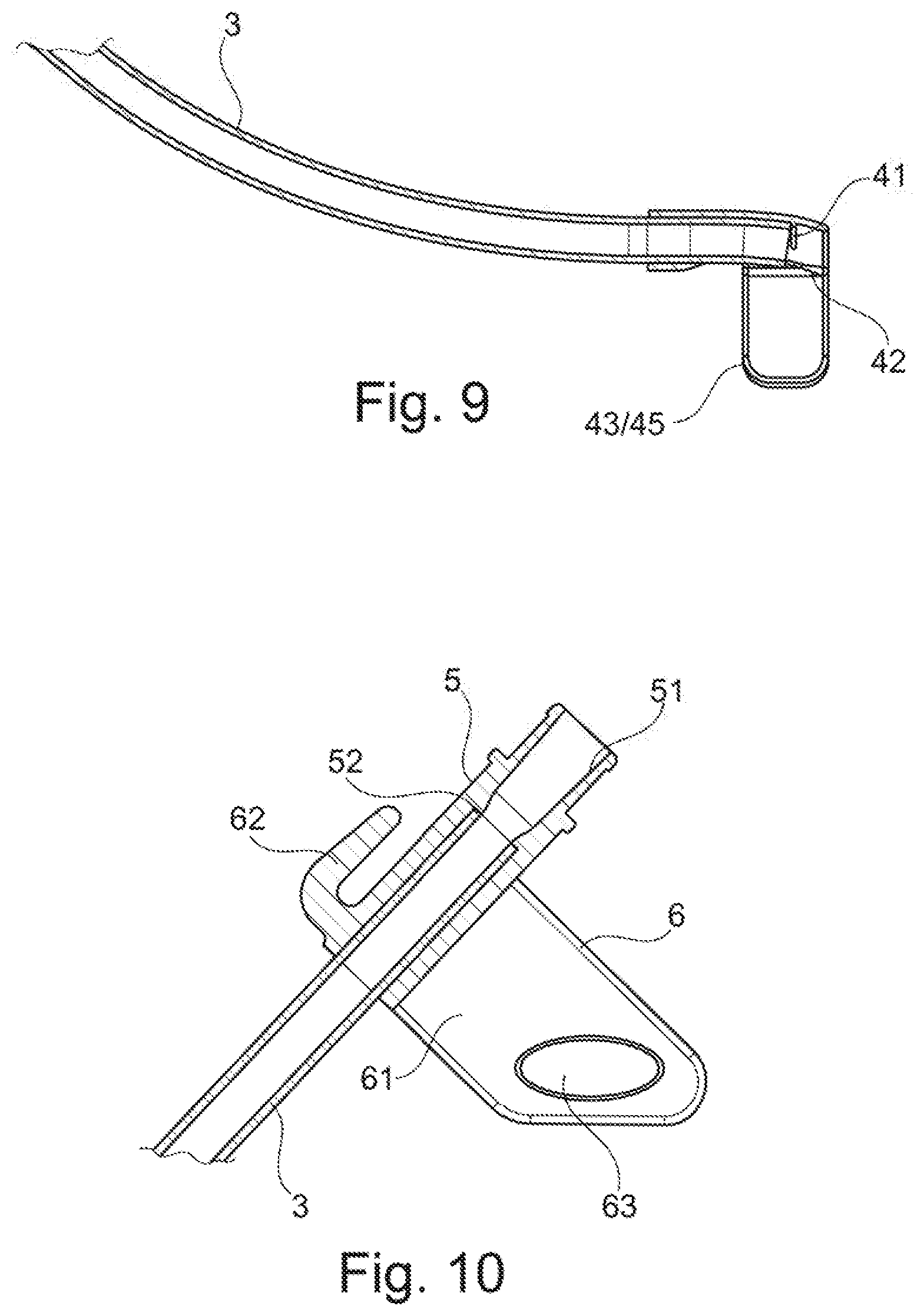
[0026] FIG. 9 shows a sectional view of the distal end cap in the preferred configuration;
[0027] FIG. 10 shows a sectional view of the proximal fixing means of the working channel device according to the first configuration;
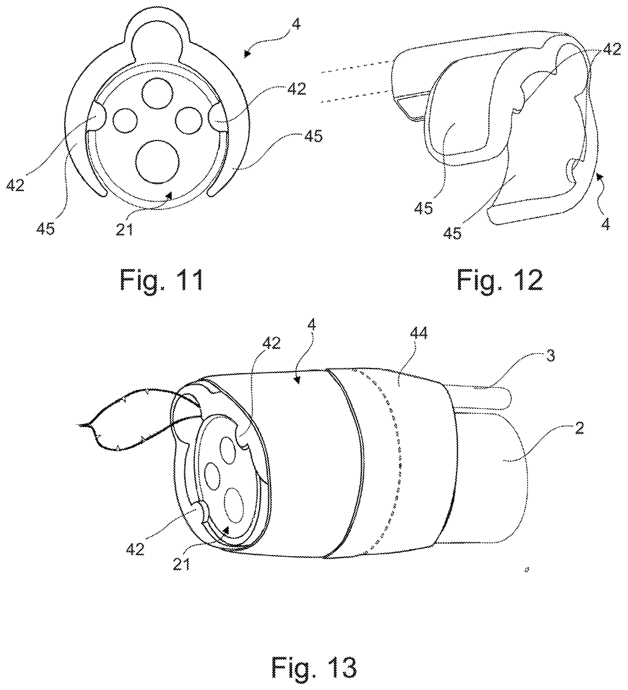
[0028] FIG. 11 shows a frontal view of a distal end cap mounted on an endoscope head according to a second configuration;
[0029] FIG. 12 shows a perspective view of the end cap according to the second configuration;
[0030] FIG. 13 shows a perspective view of the end cap mounted on an endoscope head according to the second configuration;
[0031] FIG. 14 shows a proximal fixing means of a working channel device according to a third configuration;
[0032] FIG. 15 shows a detail of an adapter arranged at the proximal fixing means with closure and valve;
[0033] FIG. 16 shows a perspective view of the proximal fixing means according to the third configuration;
[0034] FIG. 17 shows a view of a complete working channel device according to a configuration without endoscope; and
[0035] FIG. 18 shows a detail of a working channel device according to a configuration with cover hose.
DETAILED DESCRIPTION
[0036] Basically, the invention relates to a working channel device 1 for retrofitting a (commercially available) endoscope 2 of the flexible shaft design with an additional working channel 3, a so-called AWC (Additional Working Channel). Such endoscopes 2 are well known in the state of the art and are therefore only described very briefly in the following. An endoscope 2 of this type usually has an endoscope head 21 in which various functional units 25, which are not explained in more detail below, are arranged, such as an outlet of a primary (endoscope-internal) working channel, an optics for imaging and/or a lamp. Furthermore, such an endoscope 2 usually has a flexible shaft 22 with passively flexurally rigid portions and preferably an actively bendable portion (deflecting) as well as a grip 23 with various operating elements and terminals for connecting the various functional units 25 to a base station or the like.
[0037] The additional working channel 3 of the working channel device 1 according to the invention is formed by a hose 3 (or a tubular sleeve 3), which is applied during use to the endoscope shaft 22 and extends along and outside of it from the grip 23 to the endoscope head 21, so that (minimally invasive) tools and/or media can be introduced into a patient from the user side through the additional external working channel formed in this way.
[0038] For a preferred exemplary embodiment, the working channel/hose 3 is first cut to length/cut off and adapted to the length of the endoscope shaft 22. To determine the alignment and axial position of the distal outlet of the working channel/hose 3, a distal fixing means (distal cap) 4 is provided at the distal end of the working channel/hose 3. This fixing means 4 encloses the outer circumference of the endoscope head 21 in a partial circle, preferably around about 4/5 of the outer circumference of the endoscope head, with an integrally formed fixing portion 43, which forms two crescent-shaped clamping arms 45 and can thus be fixed/clipped to it in a clamping manner (see FIG. 3). As the sectional view (FIG. 9) of the distal fixing means 4 shows, it is pushed onto the working channel/hose 3 in a sleeve-like manner and is defined in relation to it via a stop 41. Preferably, the working channel/hose 3 generates by means of its inherent elasticity a clamping effect with the sleeve-like accommodation of the distal fixing means 4. The sleeve-like accommodation for the working channel/hose 3 is slotted on its side facing the fixing portion 43 and thus also serves as a spring element which, due to its inherent elasticity, enables a deflection of the crescent-shaped clamping arms 45 by overcoming a defined pre-stressing force. The partial circle-shaped fixing portion 43 also forms a stop 42, which preferably runs around the partial-circle shape of the fixing portion 43 and is complementary to the distal end circumferential edge of the endoscope head 21 in order to axially define the distal fixing means 4 with respect to the endoscope head 21. The fixing portion 43 of the distal fixing means 4 mainly interacts with the endoscope head 21 on its circumferential outer surface in order to leave the functional units lying in the front surface of the endoscope head 21 exposed or unobstructed. Preferably, the distal fixing means 4 can be additionally secured with a tape 44 against unintentional loosening due to excessive force.
[0039] The fixing portion 43 or its clamping arms 45 are positioned in FIG. 3 in an upper area facing away from the adapted endoscope 2, so that the sleeve-shaped accommodation for the hose 3 does not protrude far beyond the clamping arms 45 in the radial direction. This results in a comparatively smooth/streamlined outer contour of the frontal silhouette of the distal fixing means 4, especially in combination with a rounded design of the distal circumferential edges of the distal cap 4.
[0040] In order to ensure that the working channel/hose 3 is in contact with the endoscope shaft 22, the working channel/hose 3 is fixed to it with tapes/adhesive tapes 31 or clips (not shown), preferably with even spacing.
[0041] A preferably sleeve-shaped adapter 5 is mounted on the proximal opening of the working channel/hose 3 facing the user, which forms a, if applicable, standardized connection point/interface 51 for medical devices. In the exemplary embodiment shown, this is a Luer cone for connecting syringes and the like. The sleeve-shaped adapter 5 also forms a stop 52 running circumferentially on its inner side for the axial fixation of the working channel/hose 3 with respect to the proximal adapter 5. Here, too, the inherent elasticity of the hose 3 can advantageously form an additional force-locking connection with the adapter 5.
[0042] The working channel device 1 is attached proximally with a proximal fixing means 6, preferably on the endoscope grip 23, in particular in such a way that the adapter 5 is approximately at the height of the inlet 24 of the regular working channel of the retrofitted endoscope 20. The fixing means 6 is manufactured integrally with the adapter 5 in the exemplary embodiments shown and described below, but can also be designed as a separate modular component.
[0043] A first configuration of the proximal fixing means 6 provides two wings/fixing lugs 61 which extend away from the outer circumference of the sleeve-shaped adapter 5 in order to be able to at least partially or completely encompass an endoscope grip 23 when mounted. On the side of the outer circumference of the adapter opposite the wings 61, a hook 62 is arranged which serves to fix a Velcro tape 64 (or another tension strap). This Velcro tape/tension strap 64 can then be fixed via the hook 62 and guided through eyelets 63 at the free ends of the wings 61 to fix/tie down the proximal fixing means 6 and thus the working channel device 1 to the grip 23.
[0044] A second configuration of the proximal fixing means 6 provides for two, in particular bow-shaped (convexly curved), cantilevers 65 at the free ends of the wings 61, which are configured to grip around an endoscope grip 23 in the manner of clasps or forceps (partially circularly). The wings 61 and/or the cantilevers 65 have a certain inherent elasticity so that the grip 23 can be snapped in between them. For the secure fixation of the cantilevers 65, oppositely (concavely) curved hooks 66 are provided at their free ends. With the help of these hooks 66, the free ends of the cantilevers 65 can be secured against spreading apart by means of a rubber ring, an O-ring or the like, whereby the proximal fixing means 6 is securely held on the grip 23 of the endoscope 20. In other words, the cantilevers 65, with the hooks 66 arranged at their free ends, essentially form an .OMEGA. shape, the feet of which are secured against an opening movement by an additional elastic band.
[0045] A third configuration of the working channel device 1 differs first in that the working channel device has an additional cover hose 7. Furthermore, the design of the distal fixing means (the distal cap) 4, the adapter 5 as well as the proximal fixing means 6 is slightly different from the first and the second configuration, as explained in more detail below.
[0046] As FIGS. 11 to 13 show, the distal fixing means or respectively the distal cap 4 of the third configuration of the invention is provided with lug-like endoscope-head stops 42, which extend radially inwards from the crescent-shaped clamping arms 45 of the fixing portion 43 and form a stop with the front surface of the endoscope head 21, so that slipping of the distal cap 4 toward the proximal side is reliably prevented. In addition, the endoscope-head stops 42 facilitate a defined position of the distal outlet of the additional working channel 3 with respect to the endoscope head 21 when mounting the distal cap 4 on the endoscope head 21.
[0047] The adapter 5 of the working channel device 1 of the third configuration shown in FIG. 14 can be closed with an (integrally-manufactured) cap 53 on the one hand and on the other hand has a valve device in its interior which is not shown in further detail and which prevents unintentional intrusion of foreign bodies into the working channel 3 as well as unintentional leakage of body fluid and the like.
[0048] The proximal fixing means 6 of the third configuration shown in FIGS. 15 and 16 is similar to that of the second configuration in that it also comprises two crescent-shaped clasps 65 integrally formed with the adapter 5, which are configured to grip around an endoscope grip 23 and to be tightened against each other by means of a hook 66 formed on their distal end portions and a rubber ring 67. The proximal fixing means 6 of the third configuration of the invention has additional retaining slits or eyelets 68 which, adjacent to one of the hooks 66, are molded into the edge of the free end of the clasp 65 carrying the hook 66. The retaining slits 68 are narrower in the area of their opening and more bulbous on the inside, so that the rubber ring 67 can only be pushed/snapped through the narrow point under elastic deformation, but expands again in the bulbous area of the retaining slits 68. In this way, the rubber ring 67 is securely held at the proximal fixing means 6 and cannot slip from the hooks 66 and fall to the floor during assembly.
[0049] The cover hose 7, which was added as an additional component in the third configuration, is best seen in FIGS. 17 and 18. As shown in FIG. 18, the cover hose 7 is attached proximally behind the endoscope head 21 and pulled towards the endoscope grip 23 over the endoscope shaft 22 of the adapted endoscope 2 and the additional working channel 3. As can be seen in FIG. 18, the additional working channel 3 can, under certain circumstances, protrude slightly from the endoscope shaft 22 when the endoscope shaft 22 is bent accordingly, so that a gap is formed. In such a case, the cover hose 7 prevents tissue from becoming trapped in said gap, which could lead to tissue trauma. The working channel device 1 shown in FIG. 17 includes cable twist clips 71 for temporary fixation of the cover hose 7 during mounting as well as a small (guiding) tube 72, which makes it easier to slide the gathered cover hose 7 onto an endoscope 2 to be adapted.
[0050] In the following, a typical mounting procedure of the working channel device 1 on an endoscope 2 is described using the third configuration described above.
[0051] At first, the endoscope is pushed through the small tube 72 of the cover hose 7 included with the working channel device 1.
[0052] Subsequently, the distal fixing means 4 is placed on the endoscope tip 21 so that the stops 42 contact the front side of the endoscope tip 21. The working channel 3, which is still relatively rotatable at this point, is positioned in the circumferential direction according to the desired application. The distal fixing means is then fixed to the endoscope using the adhesive strips 31 included in the set.
[0053] The AWC adapter 5 is attached to the endoscope grip 23 with the proximal fixing means 6 on the right or left (depending on preference) next to the endoscope working channel inlet by placing the cantilevers or clasps 65 around the grip above the working channel. The adapter 5 is then secured on the clasps 65 by attaching the rubber ring 67 to the provided hooks 66.
[0054] A further adhesive strip 31 on the endoscope shaft, approx. 10 cm below the AWC adapter 5, attaches it additionally to the endoscope grip 23.
[0055] The distal cable-twist clip 71 is removed, the hose end is attached to the endoscope 2 with an adhesive strip 31 at a distance from the adhesive strips 31 of the distal fixing means and the cover hose 7 (endoscope cover) is pulled back to the proximal end of the endoscope 2 using the small tube 72. It unrolls during this process. The cover hose 7 is smoothed towards the proximal end so that there is no excess material at the distal end. The remaining cable twist clip 71 and the small tube 72 are removed. To facilitate the introduction of the system, the surface of the cover hose 7 can be reduced by distributing the additional adhesive strips 31 over the cover hose 7 with distance to each other.
* * * * *
D00000
D00001
D00002
D00003
D00004
D00005
D00006
D00007
D00008
XML
uspto.report is an independent third-party trademark research tool that is not affiliated, endorsed, or sponsored by the United States Patent and Trademark Office (USPTO) or any other governmental organization. The information provided by uspto.report is based on publicly available data at the time of writing and is intended for informational purposes only.
While we strive to provide accurate and up-to-date information, we do not guarantee the accuracy, completeness, reliability, or suitability of the information displayed on this site. The use of this site is at your own risk. Any reliance you place on such information is therefore strictly at your own risk.
All official trademark data, including owner information, should be verified by visiting the official USPTO website at www.uspto.gov. This site is not intended to replace professional legal advice and should not be used as a substitute for consulting with a legal professional who is knowledgeable about trademark law.