Detachable Nail Brush Apparatus
Bellah; Dana
U.S. patent application number 16/101433 was filed with the patent office on 2020-02-13 for detachable nail brush apparatus. The applicant listed for this patent is Dana Bellah. Invention is credited to Dana Bellah.
| Application Number | 20200046108 16/101433 |
| Document ID | / |
| Family ID | 69406934 |
| Filed Date | 2020-02-13 |


View All Diagrams
| United States Patent Application | 20200046108 |
| Kind Code | A1 |
| Bellah; Dana | February 13, 2020 |
DETACHABLE NAIL BRUSH APPARATUS
Abstract
A detachable nail brush apparatus that includes a cap portion configured to be detachably connected to a nail polish container, an elongated tubular member, a fingernail brush extending from one end of the elongated tubular member, and first and second connection members. The fingernail brush is configured to apply a nail polish to a fingernail in an operational mode. The first connection member is configured to be detachably connected to connection member. A portion of the detachable nail brush apparatus containing the fingernail brush is configured to be replaced with one or more replacements via the first and second connection members without replacing the cap portion.
| Inventors: | Bellah; Dana; (Sanderson, TX) | ||||||||||
| Applicant: |
|
||||||||||
|---|---|---|---|---|---|---|---|---|---|---|---|
| Family ID: | 69406934 | ||||||||||
| Appl. No.: | 16/101433 | ||||||||||
| Filed: | August 11, 2018 |
| Current U.S. Class: | 1/1 |
| Current CPC Class: | A45D 34/043 20130101; A46B 2200/1046 20130101; A46B 2200/01 20130101; A46B 7/042 20130101; A45D 34/045 20130101; A45D 29/12 20130101; A46B 5/0095 20130101; A46B 7/046 20130101; A46B 9/021 20130101 |
| International Class: | A46B 7/04 20060101 A46B007/04; A45D 29/12 20060101 A45D029/12; A45D 34/04 20060101 A45D034/04; A46B 5/00 20060101 A46B005/00; A46B 9/02 20060101 A46B009/02 |
Claims
1. A detachable nail brush apparatus comprising: a cap portion configured to be detachably connected to a nail polish container; an elongated tubular member; a fingernail brush extending from one end of the elongated tubular member, wherein the fingernail brush is configured to apply a nail polish to a fingernail in an operational mode; and first and second connection members, wherein the first connection member is configured to be detachably connected to connection member, and wherein a portion of the detachable nail brush apparatus containing the fingernail brush is configured to be replaced with one or more replacements via the first and second connection members without replacing the cap portion.
2. The detachable nail brush apparatus of claim 1, wherein the cap portion and the elongated tubular member comprise at least one selected from the group consisting of plastic, polyvinyl chloride, polyethylene, polypropylene, carbon fiber, glass, metal and wood.
3. The detachable nail brush apparatus of claim 2, wherein the first connection member is arranged an opposite end of the elongated tubular member, and wherein the second connection member is arranged on the cap portion.
4. The detachable nail brush apparatus of claim 3, wherein the first and second connection members form a snap fastener in which the first connection member comprises a projecting circular lip and second connection member comprises a groove configured to receive the projecting circular lip of connection member in an attached operational mode.
5. The detachable nail brush apparatus of claim 3, wherein the first and second connection members form a concentric tube annulus connector in which the first connection member comprises a circular end that projects into a circular opening of the second connection member, wherein the circular opening of second connection member is slightly larger and sized to receive the first connection member within the circular opening of the second connection member in an attached operational mode.
6. The detachable nail brush apparatus of claim 3, wherein the first and second connection members form respective mated male and female threaded connectors, and wherein the first connection member includes cylindrical grooves threaded in a spiral configuration evenly around an outer surface of the elongated tubular member, arranged and sized to fit within matching cylindrical grooves on an inner surface of an opening portion of second connection member in an attached operational mode.
7. The detachable nail brush apparatus of claim 2, wherein the first connection member and the second connection member are arranged at a middle portion of elongated tubular member.
8. The detachable nail brush apparatus of claim 7, wherein the first and second connection members form a snap fastener in which the first connection member comprises a projecting circular lip and second connection member comprises a groove configured to receive the projecting circular lip of connection member in an attached operational mode.
9. The detachable nail brush apparatus of claim 7, wherein the first and second connection members form a concentric tube annulus connector in which the first connection member comprises a circular end that projects into a circular opening of the second connection member, wherein the circular opening of second connection member is slightly larger and sized to receive the first connection member within the circular opening of the second connection member in an attached operational mode.
10. The detachable nail brush apparatus of claim 7, wherein the first and second connection members form respective mated male and female threaded connectors, and wherein the first connection member includes cylindrical grooves threaded in a spiral configuration evenly around an outer surface of the elongated tubular member, arranged and sized to fit within matching cylindrical grooves on an inner surface of an opening portion of second connection member in an attached operational mode.
11. The detachable nail brush apparatus of claim 2, wherein the first and second connection members are arranged substantially near the fingernail brush end of the elongated tubular member.
12. The detachable nail brush apparatus of claim 11, wherein the first and second connection members form a snap fastener in which the first connection member comprises a projecting circular lip and second connection member comprises a groove configured to receive the projecting circular lip of connection member in an attached operational mode.
13. The detachable nail brush apparatus of claim 11, wherein the first and second connection members form a concentric tube annulus connector in which the first connection member comprises a circular end that projects into a circular opening of the second connection member, wherein the circular opening of second connection member is slightly larger and sized to receive the first connection member within the circular opening of the second connection member in an attached operational mode.
14. The detachable nail brush apparatus of claim 11, wherein the first and second connection members form respective mated male and female threaded connectors, and wherein the first connection member includes cylindrical grooves threaded in a spiral configuration evenly around an outer surface of the elongated tubular member, arranged and sized to fit within matching cylindrical grooves on an inner surface of an opening portion of second connection member in an attached operational mode.
Description
BACKGROUND OF THE INVENTION
Field of the Invention
[0001] The present invention is generally related to disposable nail brushes, and more particularly to a detachable nail brush apparatus.
Discussion of the Background
[0002] Nail brushes known in the prior art are permanently attached to the screw cap of the nail polish container. Such a configuration requires purchasing a new polish container to get a new nail brush. Nail brushes are commonly used by more than one person. This is especially true in nail salons where the same nail brush is used by multiple customers. Often this results in contaminants. Contaminants include, without limitation, infectious organisms that may thrive and grow in the nail polish once the nail brush is redeposited into the nail polish container. Notably, but not limiting, any nail brush coming in contact with an infected nail may result in the transmission of the infection to other clients. Further, sharing a nail brush is not in the best interest of nail hygiene. Nail brushes also wear out by use and over time. For instance, a nail polish left standing on a nail brush and exposed to the air may solidify on the nail brush which results in an unusable nail brush despite possibly still having usable nail polish in the container.
[0003] For the above reasons, brushes known in the prior art are permanently attached to the screw cap of the nail polish container are problematic for sanitary and reusability reasons. Thus, there currently exist deficiencies in nail brush designs.
SUMMARY OF THE INVENTION
[0004] Accordingly, one aspect of the present invention is to provide a detachable nail brush apparatus that includes a cap portion configured to be detachably connected to a nail polish container, an elongated tubular member, a fingernail brush extending from one end of the elongated tubular member, and first and second connection members. The fingernail brush is configured to apply a nail polish to a fingernail in an operational mode. The first connection member is configured to be detachably connected to connection member. A portion of the detachable nail brush apparatus containing the fingernail brush is configured to be replaced with one or more replacements via the first and second connection members without replacing the cap portion.
BRIEF DESCRIPTION OF THE DRAWINGS
[0005] A more complete appreciation of the present invention and many of the attendant advantages thereof will be readily obtained as the same becomes better understood by reference to the following detailed description when considered in conjunction with the accompanying drawings, wherein:
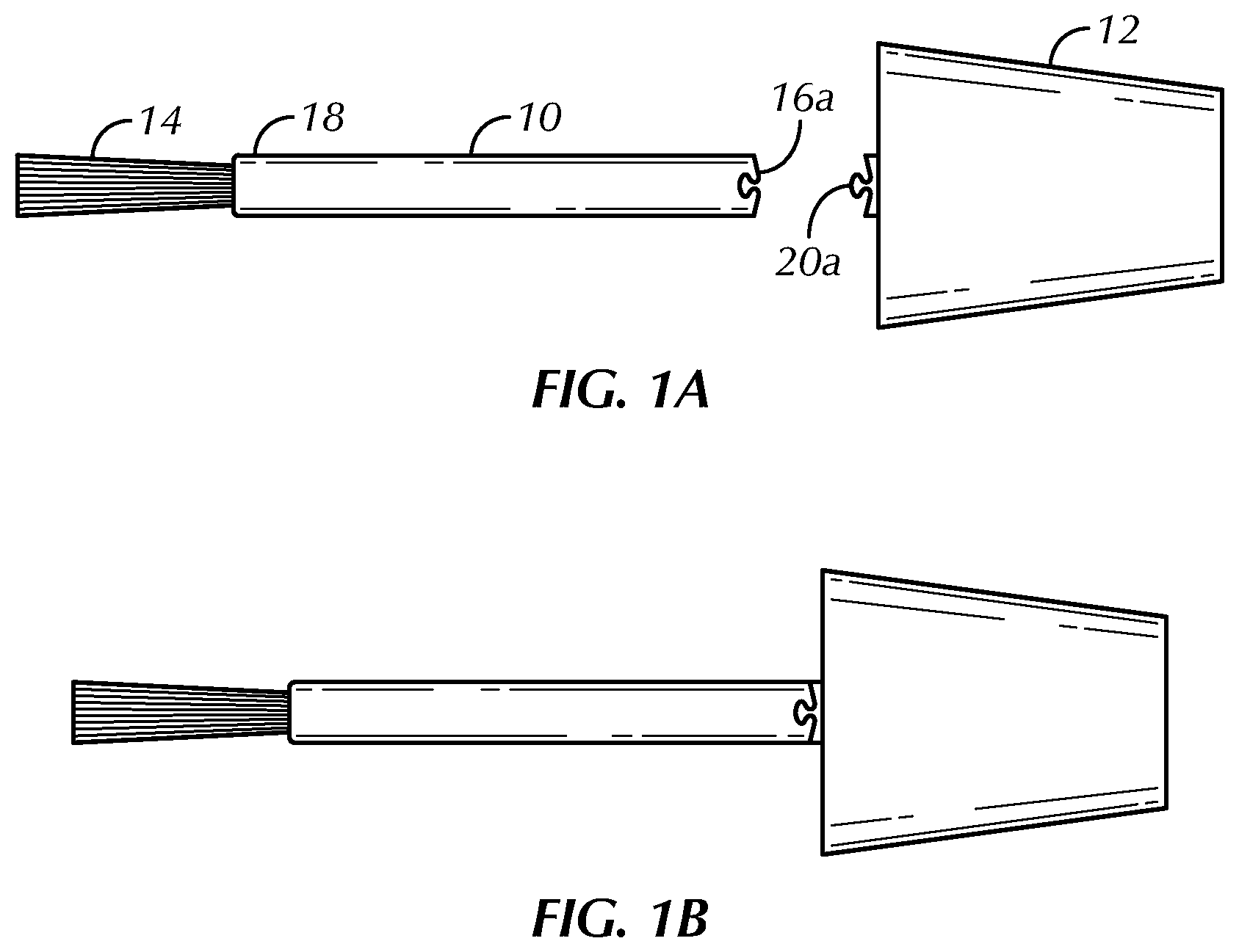
[0006] FIG. 1A is a side view of a detachable nail brush in a detached arrangement in accordance with an embodiment of the present invention;
[0007] FIG. 1B is a side view of the detachable nail brush in an attached arrangement shown in FIG. 1A;
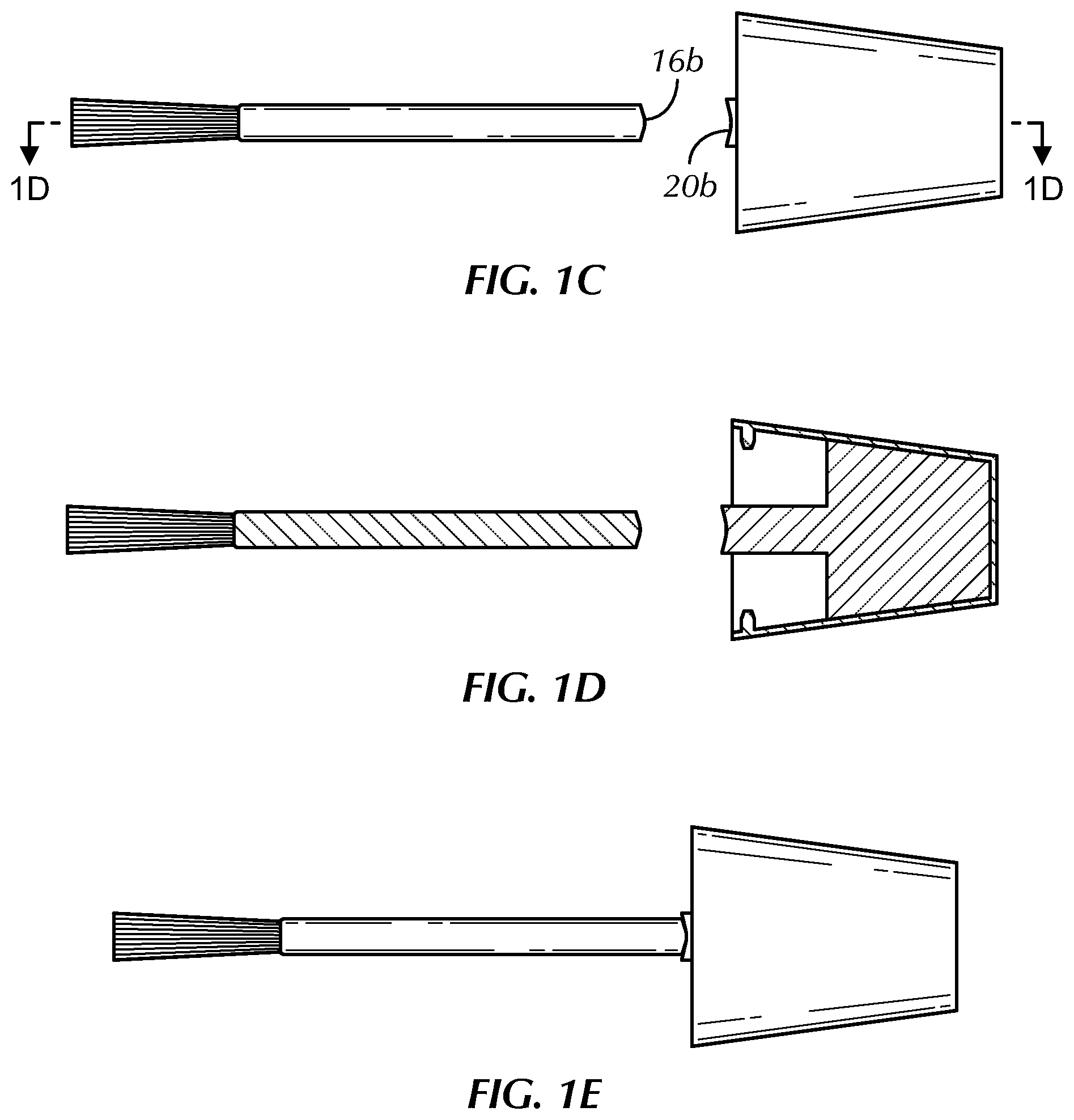
[0008] FIG. 1C is a side view of a detachable nail brush in a detached arrangement in accordance with another embodiment of the present invention;
[0009] FIG. 1D is a cross sectional view taken along line 1D-1D of the detachable nail brush shown in FIG. 1C;
[0010] FIG. 1E is a side view of the detachable nail brush in an attached arrangement shown in FIG. 1C;
[0011] FIG. 1F is a side view of a detachable nail brush in a detached arrangement in accordance with another embodiment of the present invention;
[0012] FIG. 1G is a side view of the detachable nail brush in an attached arrangement shown in FIG. 1F;
[0013] FIG. 1H is a side view of a detachable nail brush in a detached arrangement in accordance with another embodiment of the present invention;
[0014] FIG. 1I is a cross sectional view taken along line 1I-1I of the detachable nail brush shown in FIG. 1H;
[0015] FIG. 1J is a side view of the detachable nail brush in an attached arrangement shown in FIG. 1H;
[0016] FIG. 1K is a side view of a detachable nail brush in a detached arrangement in accordance with another embodiment of the present invention;
[0017] FIG. 1L is a side view of the detachable nail brush in an attached arrangement shown in FIG. 1K;
[0018] FIG. 1M is a side view of a detachable nail brush in a detached arrangement in accordance with another embodiment of the present invention;
[0019] FIG. 1N is a cross sectional view taken along line 1N-1N of the detachable nail brush shown in FIG. 1M;
[0020] FIG. 1O is a side view of the detachable nail brush in an attached arrangement shown in FIG. 1M;
[0021] FIG. 2A is a side view of a detachable nail brush in a detached arrangement in accordance with another embodiment of the present invention;
[0022] FIG. 2B is a side view of the detachable nail brush in an attached arrangement shown in FIG. 2A;
[0023] FIG. 2C is a cross sectional view taken along line 2C-2C of the detachable nail brush shown in FIG. 2A;
[0024] FIG. 2D is a side view of a detachable nail brush in a detached arrangement in accordance with another embodiment of the present invention;
[0025] FIG. 2E is a side view of the detachable nail brush in an attached arrangement shown in FIG. 2D;
[0026] FIG. 2F is a cross sectional view taken along line 2F-2F of the detachable nail brush shown in FIG. 2D;
[0027] FIG. 2G is a side view of a detachable nail brush in a detached arrangement in accordance with another embodiment of the present invention;
[0028] FIG. 2H is a side view of the detachable nail brush in an attached arrangement shown in FIG. 2G;
[0029] FIG. 2I is a cross sectional view taken along line 2I-2I of the detachable nail brush shown in FIG. 2G;
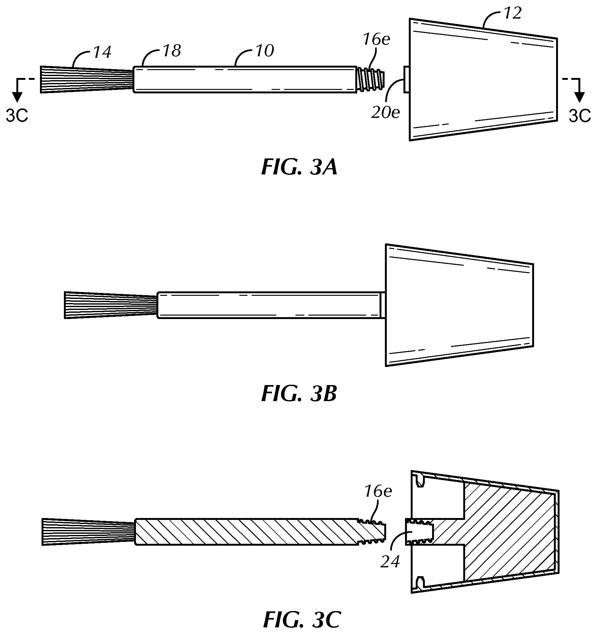
[0030] FIG. 3A is a side view of a detachable nail brush in a detached arrangement in accordance with another embodiment of the present invention;
[0031] FIG. 3B is a side view of the detachable nail brush in an attached arrangement shown in FIG. 3A;
[0032] FIG. 3C is a cross sectional view taken along line 3C-3C of the detachable nail brush shown in FIG. 3A;
[0033] FIG. 3D is a side view of a detachable nail brush in a detached arrangement in accordance with another embodiment of the present invention;
[0034] FIG. 3E is a side view of the detachable nail brush in an attached arrangement shown in FIG. 3D;
[0035] FIG. 3F is a cross sectional view taken along line 3F-3F of the detachable nail brush shown in FIG. 3D;
[0036] FIG. 3G is a side view of a detachable nail brush in a detached arrangement in accordance with another embodiment of the present invention;
[0037] FIG. 3H is a side view of the detachable nail brush in an attached arrangement shown in FIG. 3G; and
[0038] FIG. 3I is a cross sectional view taken along line 3I-3I of the detachable nail brush shown in FIG. 3G.
DETAILED DESCRIPTION THE PREFERRED EMBODIMENTS
[0039] Referring now to the drawings, wherein like reference numerals designate identical or corresponding parts throughout the several views, preferred embodiments of the present invention are described.
[0040] Referring to FIGS. 1A-3I, a detachable nail brush apparatus in accordance with embodiments of the present invention, is shown. A detachable nail brush includes a cap 12 and an elongated tubular member 10. The cap 12 and elongated tubular member 10 may be composed of, without limitation, plastic, polyvinyl chloride, polyethylene, polypropylene, carbon fiber, glass, metal, wood and the like. The cap 12 is configured to be detachably connected to a nail polish container. As is known in the art, without limitation, the cap 12 may include cylindrical grooves threaded in a spiral configuration evenly around an interior surface of the cap 12, arranged and sized to fit around matching cylindrical grooves on an outer surface of an extended opening portion of a nail polish container (not shown). However, it is to be understood that the cap 12 may be detachably connected to the nail polish container by any means now known or developed in the future. A brush 14 extends from one end 18 of the elongated tubular member 10. The brush 10 is configured to be used to apply a nail polish to a user's fingernail in an operational mode.
I. Snap Connector
[0041] FIGS. 1A and 1B depict a first embodiment of the present invention in respectively a detached arrangement and an attached arrangement. According to this non-limiting embodiment, an opposite end of the elongated tubular member 10 includes connection member 16a. Likewise, the cap 12 includes connection member 20a. The connection member 16a is configured to be detachably connected to connection member 20a. According to this embodiment, connection member 16a and connection member 20a form a snap fastener in which connection member 20a comprises a projecting circular lip and connection member 16a comprises a groove configured to receive the projecting circular lip of connection member 20a in an attached operational mode as shown in FIG. 1B. However, it is understood that the projecting circular lip and the groove may be on either the cap 12 or the elongated tubular member 10 without departing from the scope of the present invention. Further, non-circular shapes are also possible within the scope of the present invention.
[0042] FIGS. 1F and 1G depict a second embodiment of the present invention in respectively a detached arrangement and an attached arrangement. According to this non-limiting embodiment, an opposite end of the elongated tubular member 10 is permanently connected to cap 12 by any known means. The elongated tubular member 10 comprises two elongated tubular portions each respectively having connection members 16a and 20a at a middle portion of elongated tubular member 10. The connection member 16a is configured to be detachably connected to connection member 20a. According to this embodiment, connection member 16a and connection member 20a form a snap fastener in which connection member 20a comprises a projecting circular lip and connection member 16a comprises a groove configured to receive the projecting circular lip of connection member 20a in an attached operational mode as shown in FIG. 1G. However, it is understood that the projecting circular lip and the groove may be on either end of the two elongated tubular portions of the elongated tubular member 10 without departing from the scope of the present invention. Further, non-circular shapes are also possible within the scope of the present invention.
[0043] FIGS. 1K and 1L depict a third embodiment of the present invention in respectively a detached arrangement and an attached arrangement. According to this non-limiting embodiment, an opposite end of the elongated tubular member 10 is permanently connected to cap 12 by any known means. The elongated tubular member 10 comprises a tubular portion near end 18 of the elongated tubular member 10 and an elongated tubular portion, each respectively having connection members 16a and 20a. The connection member 16a is configured to be detachably connected to connection member 20a. According to this embodiment, connection member 16a and connection member 20a form a snap fastener in which connection member 20a comprises a projecting circular lip and connection member 16a comprises a groove configured to receive the projecting circular lip of connection member 20a in an attached operational mode as shown in FIG. 1G. However, it is understood that the projecting circular lip and the groove may be on either end of the two elongated tubular portions of the elongated tubular member 10 without departing from the scope of the present invention. Further, non-circular shapes are also possible within the scope of the present invention.
[0044] FIGS. 2A and 2B depict a fourth embodiment of the present invention in respectively a detached arrangement and an attached arrangement. According to this non-limiting embodiment, an opposite end of the elongated tubular member 10 includes connection member 16c. Likewise, the cap 12 includes connection member 20c. The connection member 16c is configured to be detachably connected to connection member 20c. According to this embodiment, connection member 16c and connection member 20c form a snap fastener in which connection member 20c comprises a projecting circular lip and connection member 16c comprises a groove configured to receive the projecting circular lip of connection member 20c in an attached operational mode as shown in FIG. 2B. However, it is understood that the projecting circular lip and the groove may be on either the cap 12 or the elongated tubular member 10 without departing from the scope of the present invention. Further, non-circular shapes are also possible within the scope of the present invention.
[0045] FIGS. 2D and 2E depict a fifth embodiment of the present invention in respectively a detached arrangement and an attached arrangement. According to this non-limiting embodiment, an opposite end of the elongated tubular member 10 is permanently connected to cap 12 by any known means. The elongated tubular member 10 comprises two elongated tubular portions each respectively having connection members 16c and 20c at a middle portion of elongated tubular member 10. The connection member 16c is configured to be detachably connected to connection member 20c. According to this embodiment, connection member 16c and connection member 20c form a snap fastener in which connection member 20c comprises a projecting circular lip and connection member 16c comprises a groove configured to receive the projecting circular lip of connection member 20c in an attached operational mode as shown in FIG. 2E. However, it is understood that the projecting circular lip and the groove may be on either end of the two elongated tubular portions of the elongated tubular member 10 without departing from the scope of the present invention. Further, non-circular shapes are also possible within the scope of the present invention.
[0046] FIGS. 2G and 2H depict a sixth embodiment of the present invention in respectively a detached arrangement and an attached arrangement. According to this non-limiting embodiment, an opposite end of the elongated tubular member 10 is permanently connected to cap 12 by any known means. The elongated tubular member 10 comprises a tubular portion near end 18 of the elongated tubular member 10 and an elongated tubular portion, each respectively having connection members 16c and 20c. The connection member 16c is configured to be detachably connected to connection member 20c. According to this embodiment, connection member 16c and connection member 20c form a snap fastener in which connection member 20c comprises a projecting circular lip and connection member 16c comprises a groove configured to receive the projecting circular lip of connection member 20c in an attached operational mode as shown in FIG. 2H. However, it is understood that the projecting circular lip and the groove may be on either end of the two elongated tubular portions of the elongated tubular member 10 without departing from the scope of the present invention. Further, non-circular shapes are also possible within the scope of the present invention.
II. Concentric Tube Annulus Connector
[0047] FIGS. 1C and 1E depict a seventh embodiment of the present invention in respectively a detached arrangement and an attached arrangement. FIG. 1D depicts a cross sectional view taken along line 1D-1D of the detachable nail brush shown in FIG. 1C. According to this non-limiting embodiment, an opposite end of the elongated tubular member 10 includes connection member 16b. Likewise, the cap 12 includes connection member 20b. The connection member 16b is configured to be detachably connected to connection member 20b. According to this embodiment, connection member 16b and connection member 20b form a concentric tube annulus connector in which connection member 16b comprises a circular end that projects into a circular opening of connection member 20b. The circular opening of connection member 20b is slightly larger and sized to receive connection member 16b within its circular opening in an attached operational mode as shown in FIG. 1E. However, it is understood that connection member 20b may comprise a circular end that projects into a circular opening of connection member 16b without departing from the scope of the present invention. Further, non-circular shapes are also possible within the scope of the present invention.
[0048] FIGS. 1H and 1J depict an eighth embodiment of the present invention in respectively a detached arrangement and an attached arrangement. FIG. 1I depicts a cross sectional view taken along line 1I-1I of the detachable nail brush shown in FIG. 1H. According to this non-limiting embodiment, an opposite end of the elongated tubular member 10 is permanently connected to cap 12 by any known means. The elongated tubular member 10 comprises two elongated tubular portions each respectively having connection members 16a and 20a at a middle portion of elongated tubular member 10. The connection member 16b is configured to be detachably connected to connection member 20b. According to this embodiment, connection member 16b and connection member 20b form a concentric tube annulus connector in which connection member 16b comprises a circular end that projects into a circular opening of connection member 20b. The circular opening of connection member 20b is slightly larger and sized to receive connection member 16b within its circular opening in an attached operational mode as shown in FIG. 1J. However, it is understood that connection member 20b may comprise a circular end that projects into a circular opening of connection member 16b without departing from the scope of the present invention. Further, non-circular shapes are also possible within the scope of the present invention.
[0049] FIGS. 1M and 1O depict a ninth embodiment of the present invention in respectively a detached arrangement and an attached arrangement. FIG. 1N depicts a cross sectional view taken along line 1N-1N of the detachable nail brush shown in FIG. 1M. According to this non-limiting embodiment, an opposite end of the elongated tubular member 10 is permanently connected to cap 12 by any known means. The elongated tubular member 10 comprises a tubular portion near end 18 of the elongated tubular member 10 and an elongated tubular portion, each respectively having connection members 16a and 20a. The connection member 16b is configured to be detachably connected to connection member 20b. According to this embodiment, connection member 16b and connection member 20b form a concentric tube annulus connector in which connection member 16b comprises a circular end that projects into a circular opening of connection member 20b. The circular opening of connection member 20b is slightly larger and sized to receive connection member 16b within its circular opening in an attached operational mode as shown in FIG. 1O. However, it is understood that connection member 20b may comprise a circular end that projects into a circular opening of connection member 16b without departing from the scope of the present invention. Further, non-circular shapes are also possible within the scope of the present invention.
III. Male and Female Threaded Connector
[0050] FIGS. 3A and 3B depict a tenth embodiment of the present invention in respectively a detached arrangement and an attached arrangement. FIG. 3C depicts a cross sectional view taken along line 3C-3C of the detachable nail brush shown in FIG. 3A. According to this non-limiting embodiment, an opposite end of the elongated tubular member 10 includes connection member 16e. Likewise, the cap 12 includes connection member 20e. The connection member 16e is configured to be detachably connected to connection member 20e. According to this embodiment, connection member 16e and connection member 20e comprise respectively mated male and female threaded connectors. Connection member 16e includes cylindrical grooves threaded in a spiral configuration evenly around an outer surface of the elongated tubular member 10, arranged and sized to fit within matching cylindrical grooves on an inner surface of an opening portion of connection member 20e in an attached operational mode as shown in FIG. 3B. However, it is understood that connection member 20e may project into a circular opening of connection member 16e without departing from the scope of the present invention.
[0051] FIGS. 3D and 3E depict an eleventh embodiment of the present invention in respectively a detached arrangement and an attached arrangement. FIG. 3F depicts a cross sectional view taken along line 3F-3F of the detachable nail brush shown in FIG. 3D. According to this non-limiting embodiment, an opposite end of the elongated tubular member 10 is permanently connected to cap 12 by any known means. The elongated tubular member 10 comprises two elongated tubular portions each respectively having connection members 16e and 20e at a middle portion of elongated tubular member 10. The connection member 16e is configured to be detachably connected to connection member 20e. According to this embodiment, connection member 16e and connection member 20e comprise respectively mated male and female threaded connectors. Connection member 16e includes cylindrical grooves threaded in a spiral configuration evenly around an outer surface of the elongated tubular member 10, arranged and sized to fit within matching cylindrical grooves on an inner surface of an opening portion of connection member 20e in an attached operational mode as shown in FIG. 3E. However, it is understood that connection member 20e may project into a circular opening of connection member 16e without departing from the scope of the present invention.
[0052] FIGS. 3G and 3H depict a twelfth embodiment of the present invention in respectively a detached arrangement and an attached arrangement. FIG. 3I depicts a cross sectional view taken along line 3I-3I of the detachable nail brush shown in FIG. 3G. According to this non-limiting embodiment, an opposite end of the elongated tubular member 10 is permanently connected to cap 12 by any known means. The elongated tubular member 10 comprises a tubular portion near end 18 of the elongated tubular member 10 and an elongated tubular portion, each respectively having connection members 16e and 20e. The connection member 16e is configured to be detachably connected to connection member 20e. According to this embodiment, connection member 16e and connection member 20e comprise respectively mated male and female threaded connectors. Connection member 16e includes cylindrical grooves threaded in a spiral configuration evenly around an outer surface of the elongated tubular member 10, arranged and sized to fit within matching cylindrical grooves on an inner surface of an opening portion of connection member 20e in an attached operational mode as shown in FIG. 3H. However, it is understood that connection member 20e may project into a circular opening of connection member 16e without departing from the scope of the present invention.
[0053] It will be apparent to those skilled in the art that various modifications and variations can be made in the system and method of the present invention without departing form the spirit or scope of the invention. Thus, it is intended that the present invention cover the modifications and variations of the invention provided they come within the scope of the appended claims and their equivalents.
[0054] Obviously, many other modifications and variations of the present invention are possible in light of the above teachings. The specific embodiments discussed herein are merely illustrative, and are not meant to limit the scope of the present invention in any manner. It is therefore to be understood that within the scope of the disclosed concept, the invention may be practiced otherwise than as specifically described.
* * * * *
D00000
D00001
D00002
D00003
D00004
D00005
D00006
D00007
D00008
D00009
D00010
D00011
D00012

XML
uspto.report is an independent third-party trademark research tool that is not affiliated, endorsed, or sponsored by the United States Patent and Trademark Office (USPTO) or any other governmental organization. The information provided by uspto.report is based on publicly available data at the time of writing and is intended for informational purposes only.
While we strive to provide accurate and up-to-date information, we do not guarantee the accuracy, completeness, reliability, or suitability of the information displayed on this site. The use of this site is at your own risk. Any reliance you place on such information is therefore strictly at your own risk.
All official trademark data, including owner information, should be verified by visiting the official USPTO website at www.uspto.gov. This site is not intended to replace professional legal advice and should not be used as a substitute for consulting with a legal professional who is knowledgeable about trademark law.