Sound Device And Assembling Method Therefor
Wang; Chengliang ; et al.
U.S. patent application number 16/524208 was filed with the patent office on 2020-02-06 for sound device and assembling method therefor. The applicant listed for this patent is AAC ACOUSTIC TECHNOLOGIES (SHENZHEN) CO., LTD.. Invention is credited to Zhisheng Chen, Quan Shen, Chengliang Wang.
| Application Number | 20200045488 16/524208 |
| Document ID | / |
| Family ID | 64852092 |
| Filed Date | 2020-02-06 |


| United States Patent Application | 20200045488 |
| Kind Code | A1 |
| Wang; Chengliang ; et al. | February 6, 2020 |
SOUND DEVICE AND ASSEMBLING METHOD THEREFOR
Abstract
The present disclosure provides a sound device, comprising a housing and a sound unit received in the housing, wherein, the housing comprises an upper cover plate with a receiving space, the upper cover plate is made of 3D glass, and the upper cover plate and the sound unit are fixed to each other by laser welding. The sound device provided by the present disclosure replacing the housing with a 3D glass housing, and thus enhances the strength of the housing, and the sealing and fixing is implemented by laser welding due to the transparent property of the 3D glass, which effectively prevents overflowing caused by gluing and ultrasonic welding, meanwhile the maximum cavity is ensured and the usage of the antenna will not be affected.
| Inventors: | Wang; Chengliang; (Shenzhen, CN) ; Chen; Zhisheng; (Shenzhen, CN) ; Shen; Quan; (Shenzhen, CN) | ||||||||||
| Applicant: |
|
||||||||||
|---|---|---|---|---|---|---|---|---|---|---|---|
| Family ID: | 64852092 | ||||||||||
| Appl. No.: | 16/524208 | ||||||||||
| Filed: | July 29, 2019 |
| Current U.S. Class: | 1/1 |
| Current CPC Class: | H04R 31/006 20130101; H04R 2499/11 20130101; B23K 26/21 20151001; H04R 1/2811 20130101; H04R 1/026 20130101; H04R 9/045 20130101; H04R 9/06 20130101; H04R 1/2888 20130101; B23K 2103/54 20180801; H04R 1/025 20130101 |
| International Class: | H04R 31/00 20060101 H04R031/00; H04R 9/06 20060101 H04R009/06; H04R 1/02 20060101 H04R001/02; H04R 1/28 20060101 H04R001/28; H04R 9/04 20060101 H04R009/04; B23K 26/21 20060101 B23K026/21 |
Foreign Application Data
| Date | Code | Application Number |
|---|---|---|
| Aug 2, 2018 | CN | 201810873819.7 |
Claims
1. A sound device, comprising a housing and a sound unit received in the housing, wherein, the housing comprises an upper cover plate with a receiving space, the upper cover plate is made of 3D glass, the upper cover plate and the sound unit are fixed to each other by laser welding.
2. The sound device according to claim 1, wherein, the sound unit is provided with a casing, and the casing is a plastic casing.
3. The sound device according to claim 1, wherein, the housing further comprises a lower cover plate fitting with the upper cover plate, and the lower cover plate is made of 3D glass.
4. The sound device according to claim 3, wherein, the upper cover and the lower cover are fixed to each other by laser welding.
5. An assembling method for a sound device, comprising the steps of: providing a sound unit and a housing, the housing is made of 3D glass; and disposing the sound unit in the housing, and fixing the sound unit and the housing with each other by using laser welding outside the housing, so as to form a sound device by assembling.
6. The assembling method for a sound device according to claim 5, wherein the housing comprises an upper cover plate and a lower cover plate fitted with the upper cover plate, the step for fixing the sound unit and the housing comprises: disposing the sound unit within the upper cover plate, and fixing the sound unit with the upper cover plate with each other by using laser welding outside the upper cover plate, by taking a fitting surface between the sound unit and the upper cover plate as a path; and assembling the lower cover plate with the upper cover plate to form the housing, wherein, fixing the lower cover plate and the upper cover plate with each other by using laser welding outside the housing, by taking a fitting surface between lower cover plate and the upper cover plate as a path.
7. The assembling method for a sound device according to claim 6, wherein the step for fixing the sound unit and the upper cover comprises: disposing the sound unit within the upper cover; filling a sealant along sides of the sound unit; flipping after the sealant is cured; and fixing the sound unit and the upper cover plate with each other by using laser welding outside the upper cover plate, by taking a fitting surface between the sound unit and the upper cover plate as a path.
Description
TECHNICAL FIELD
[0001] The present disclosure relates to the field of electro-acoustic conversion technology, and in particular, to a sound device and an assembling method therefor.
BACKGROUND
[0002] Recently, information technology develops rapidly, and audio equipment have become more popular. User's demand for audio equipment is not limited to playback of videos and audios, but there is also a demand for improving reliability of audio equipment. As 5G times is coming, mobile multimedia technology is developed, and many audio equipment have a variety of entertainment functions, such as video playback, digital photography, games, GPS navigation, etc. As the demand for functions increases, the integrity of the elements and devices built within the audio apparatuses becomes higher and the requirement for high quality of products becomes stricter.
[0003] In audio equipment, a sound device is a commonly used electronic device, it is mainly used for audio signal playback, and the structural design thereof directly affects the quality of audio playback. A sound device according to the related art includes a housing with a housing space, and a sound unit received in the housing space.
[0004] In a sound device according to the related art, the housing is generally a plastic housing or a steel sheet is generally embedded in the plastic housing, so as to ensure the strength of the housing. However, the thickness of the plastic housing is limited to 0.50 mm or more generally, which makes the housing space insufficient; besides, the steel sheet cannot be used in a large area due to the influence of the antenna.
[0005] Therefore, it is necessary to provide a new sound device to solve the above technical problems.
BRIEF DESCRIPTION OF THE DRAWINGS
[0006] In order to more clearly describe the technical solutions in the embodiments of the present disclosure, the drawings used in the description of the embodiments will be briefly described below. It is obvious that the drawings in the following description only relate to some embodiments of the present disclosure. For those skilled in the art, other drawings may also be obtained according to the accompanying drawings without any creative work, wherein:
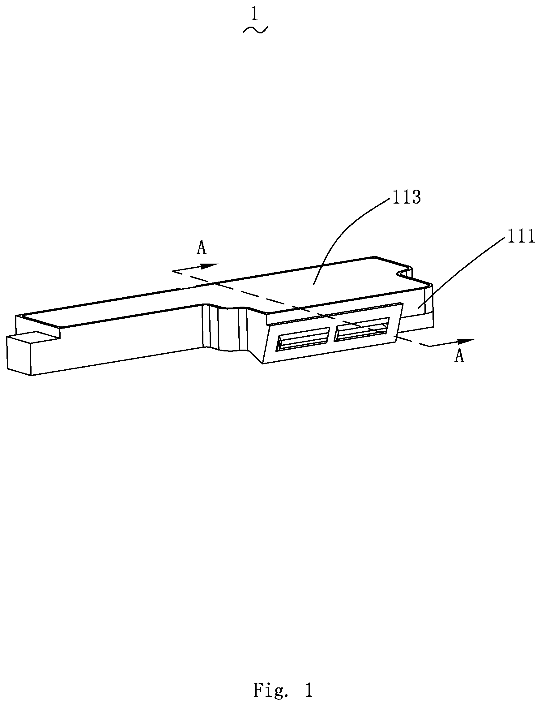
[0007] FIG. 1 is a perspective assembled view of a sound device provided by the present disclosure;
[0008] FIG. 2 is a perspective exploded view of the sound device as shown in FIG. 1;
[0009] FIG. 3 is a cross-sectional view of the sound device as shown in FIG. 1 taken along line A-A;
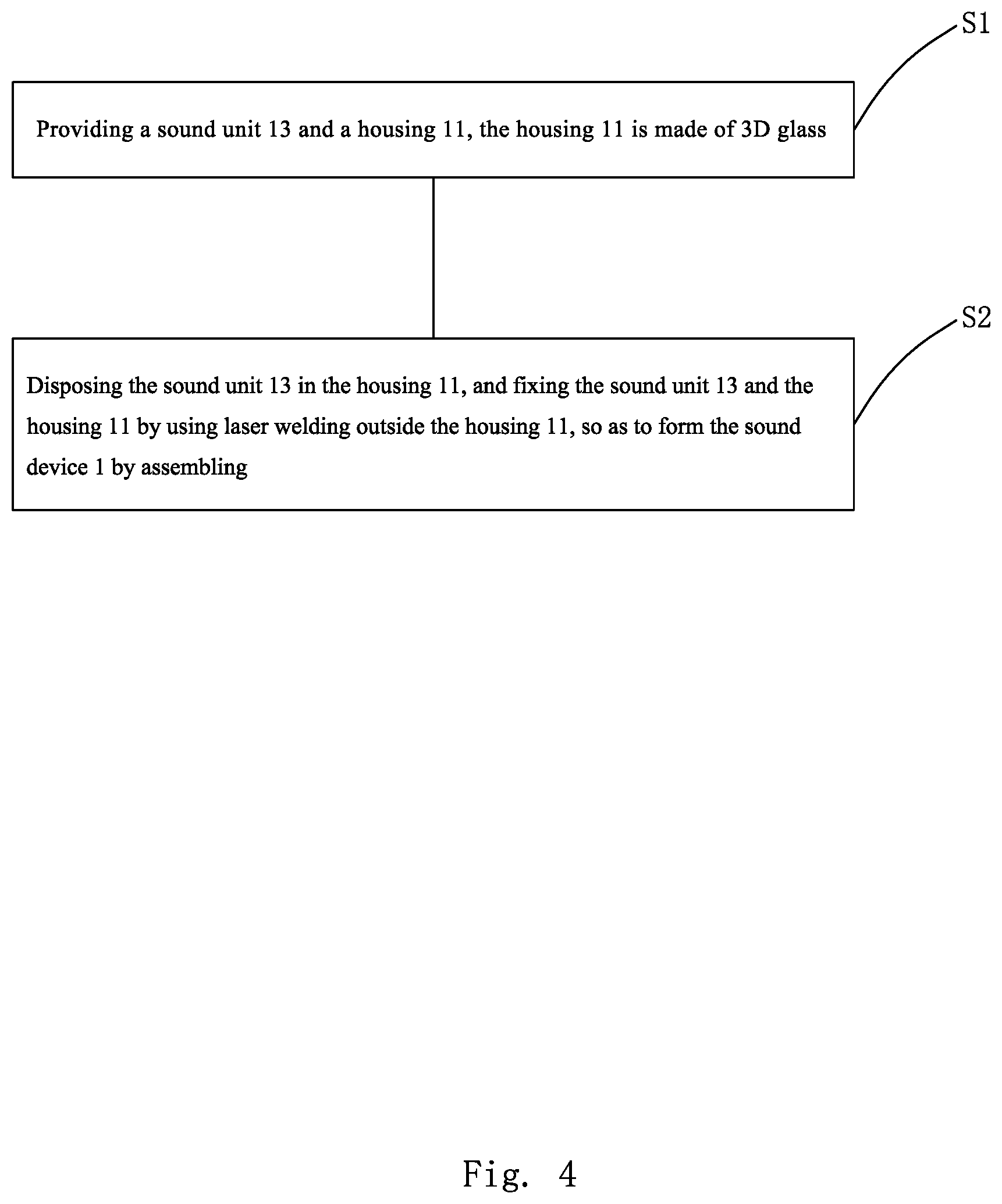
[0010] FIG. 4 is a flow chart of an assembling method for the sound device as shown in FIG. 1;
[0011] FIG. 5 is a schematic flow chart illustrating the step S2 in the assembling method for the sound device as shown in FIG. 4;
[0012] FIG. 6 is a schematic flow chart illustrating the step S21 in the step S2 as shown in FIG. 5.
DETAILED DESCRIPTION
[0013] The technical solutions in the embodiments of the present disclosure are clearly and completely described in the following with reference to the accompanying drawings in the embodiments of the present disclosure. It is obvious that the described embodiments are only a part of the embodiments of the present disclosure, but not all of the embodiments. All other embodiments, obtained by a person of ordinary skill in the art based on the embodiments of the present disclosure without creative work, fall within the scope of the present disclosure.
[0014] Please refer to FIG. 1 to FIG. 3, FIG. 1 is a perspective assembled view of a sound device provided by the present disclosure; FIG. 2 is a perspective exploded view of the sound device as shown in FIG. 1; FIG. 3 is a cross-sectional view of the sound device as shown in FIG. 1, taken along line A-A. The present disclosure provides a sound device 1 including a housing 11 and a sound unit 13 received in the housing 11.
[0015] The housing 11 includes an upper cover plate 111 having a receiving space 110 and a lower cover plate 113 fitting with the upper cover plate 111. The sound unit 13 is received in the receiving space 110. Both the upper cover plate 111 and the lower cover plate 113 are made of 3D glass, that is, the housing 11 is a 3D glass housing, and the upper cover plate 111 and the sound unit 13 are fixed to each other by laser welding, and the upper cover plate 111 and lower cover plate 113 are also fixed to each other by laser welding.
[0016] Specifically, the 3D glass is a glass product with non-equal wall thickness processed by hot bending-molding, and it has a curvature and transparent property. When assembling with the sound unit 13, a certain area is selectively heated by using energy of laser. The laser may pass though the 3D glass, and a focus length of the laser may be adjusted such that the focus of the laser overlap with a step surface of a diaphragm of the sound unit 13, and the energy of the laser may be adjusted, so that the 3D glass contacted with the sound unit 13 is melt by heating, thereby forming a sealing and fixing ring, and thus the process of fixing and sealing between the above upper cover plate 111 and the sound unit 13 is completed, which effectively prevents overflowing caused by gluing and ultrasonic welding. The strength of 3D glass is better, and thus it is easy to use a thin-wall thickness molding (0.30 mm or less) technology, so that phenomenons such as shell vibration would not be presented inside the cavity of the housing 11. In addition, as 3D glass is a kind of non-metallic material, the usage of the antenna will not be affected.
[0017] The sound unit 13 is provided with a casing, and the casing may be a plastic casing.
[0018] Please refer to FIG. 4, FIG. 4 low chart of an assembling method for the sound device as shown in FIG. 1. The present disclosure also provides an assembling method for a sound device, which comprises the following steps:
[0019] Step S1, providing the sound unit 13 and the housing 11, the housing 11 is made of 3D glass;
[0020] Step S2, disposing the sound unit 13 within the housing 11, and fixing the sound unit 13 and the housing 11 with each other by using laser welding outside the housing 11, so as to form the sound device 1 by assembling.
[0021] Please refer to FIG. 5, FIG. 5 is a schematic flow chart showing step S2 in the assembling method for the sound device as shown in FIG. 4. Specifically, in step S2, the assembling step for the sound unit 13 and the housing 11 includes:
[0022] Step S21, disposing the sound unit 13 within the upper cover plate 111, and fixing the sound unit 13 and the upper cover plate 111 with each other by using laser welding outside the upper cover plate 111, by taking a fitting surface between the sound unit 13 and the upper cover plate 111 as a path.
[0023] Please refer to FIG. 6, FIG. 6 is a schematic flow chart illustrating the step S21 in the step S2 as shown in FIG. 5, the assembling step for the sound unit 13 and the upper cover plate 111 includes:
[0024] Step S211, disposing the sound unit 13 in the upper cover plate 111;
[0025] Step S212, filling a sealant along sides of the sound unit 13;
[0026] Step S213, flipping after the sealant is cured; and
[0027] Step S214, fixing the sound unit 13 and the upper cover plate 111 with each other by using laser welding outside the upper cover plate 111, by taking a fitting surface between the sound unit 13 and the upper cover plate 111 as a path.
[0028] Step S22, assembling the lower cover plate 113 and the upper cover plate 111 to form the housing 11, and fixing the lower cover plate 113 and the upper cover plate 111 with each other by using laser welding outside the housing 11, by taking a fitting surface between lower cover plate 113 and the upper cover plate 111 as a path.
[0029] The above description only illustrates the embodiments of the present disclosure. It should be noted that those skilled in the art may make improvements thereto without departing from the inventive concept of the present disclosure, which shall be considered as falling within the protection scope of the present disclosure.
* * * * *
D00000
D00001
D00002
D00003
D00004
D00005
D00006
XML
uspto.report is an independent third-party trademark research tool that is not affiliated, endorsed, or sponsored by the United States Patent and Trademark Office (USPTO) or any other governmental organization. The information provided by uspto.report is based on publicly available data at the time of writing and is intended for informational purposes only.
While we strive to provide accurate and up-to-date information, we do not guarantee the accuracy, completeness, reliability, or suitability of the information displayed on this site. The use of this site is at your own risk. Any reliance you place on such information is therefore strictly at your own risk.
All official trademark data, including owner information, should be verified by visiting the official USPTO website at www.uspto.gov. This site is not intended to replace professional legal advice and should not be used as a substitute for consulting with a legal professional who is knowledgeable about trademark law.