Systems And Methods For Improved Uplink Coverage
Rudolf; Marian ; et al.
U.S. patent application number 16/599162 was filed with the patent office on 2020-02-06 for systems and methods for improved uplink coverage. This patent application is currently assigned to InterDigital Patent Holdings, Inc.. The applicant listed for this patent is InterDigital Patent Holdings, Inc.. Invention is credited to Christopher R. Cave, Muhammad U. Fazili, Lakshmi R. Iyer, Paul Marinier, Diana Pani, Ghyslain Pelletier, Marian Rudolf.
| Application Number | 20200044781 16/599162 |
| Document ID | / |
| Family ID | 47714552 |
| Filed Date | 2020-02-06 |


| United States Patent Application | 20200044781 |
| Kind Code | A1 |
| Rudolf; Marian ; et al. | February 6, 2020 |
SYSTEMS AND METHODS FOR IMPROVED UPLINK COVERAGE
Abstract
Systems and method are specified to improve the reception of UL transmission, for example in power or coverage limited situations. A WTRU may modify procedures to increase the available signal energy for reception at an eNB and/or to make more efficient use of the available signal energy at the receiver for processing UL transmissions. Example methods for increasing UL link coverage may include modifying HARQ timing (e.g., shorter HARQ), using longer TTIs, use of dedicated PUSCH allocations, use of new PUSCH modulations, enhanced reference signal design, UL macro diversity reception for PUSCH, utilizing protocol reduction techniques, ensuring in-order packet delivery, and/or utilizing a configuration for coverage limited/power limited modes of operation. The proposed methods may be applied individually or in any combination.
| Inventors: | Rudolf; Marian; (Montreal, CA) ; Marinier; Paul; (Brossard, CA) ; Pani; Diana; (Montreal, CA) ; Pelletier; Ghyslain; (Montreal, CA) ; Cave; Christopher R.; (Dollard-des-Ormeaux, CA) ; Iyer; Lakshmi R.; (King of Prussia, PA) ; Fazili; Muhammad U.; (Audubon, PA) | ||||||||||
| Applicant: |
|
||||||||||
|---|---|---|---|---|---|---|---|---|---|---|---|
| Assignee: | InterDigital Patent Holdings,
Inc. Wilmington DE |
||||||||||
| Family ID: | 47714552 | ||||||||||
| Appl. No.: | 16/599162 | ||||||||||
| Filed: | October 11, 2019 |
Related U.S. Patent Documents
| Application Number | Filing Date | Patent Number | ||
|---|---|---|---|---|
| 15667519 | Aug 2, 2017 | 10491335 | ||
| 16599162 | ||||
| 14374504 | Jul 24, 2014 | 9762356 | ||
| PCT/US2013/022916 | Jan 24, 2013 | |||
| 15667519 | ||||
| 61611799 | Mar 16, 2012 | |||
| 61611972 | Mar 16, 2012 | |||
| 61590292 | Jan 24, 2012 | |||
| Current U.S. Class: | 1/1 |
| Current CPC Class: | H04W 72/0446 20130101; H04L 1/1678 20130101; H04W 72/042 20130101; H04L 1/1893 20130101; H04L 5/0007 20130101; H04W 72/0413 20130101; H04L 1/1864 20130101; H04L 1/1822 20130101; H04L 1/1887 20130101 |
| International Class: | H04L 1/16 20060101 H04L001/16; H04L 5/00 20060101 H04L005/00; H04W 72/04 20060101 H04W072/04; H04L 1/18 20060101 H04L001/18 |
Claims
1-20. (canceled)
21. A method implemented in a wireless transmit/receive unit (WTRU), the method comprising: the WTRU receiving a configuration comprising a plurality of sets of uplink transmission timing parameters, wherein each set of uplink transmission timing parameters comprises respective uplink transmission start position information, the respective uplink transmission start position information indicating when the WTRU is to start an uplink transmission after receiving an uplink grant when using a corresponding set of uplink transmission timing parameters; the WTRU receiving a first physical downlink control channel (PDCCH) transmission comprising a first uplink grant, wherein the first uplink grant comprises an index indicating which set of the plurality of sets of uplink transmission timing parameters is to be used for the first uplink grant; the WTRU determining a start time for a first uplink transmission associated with the first uplink grant based on the uplink transmission start position information comprised in the set of uplink transmission timing parameters indicated by the index comprised in the first uplink grant; and the WTRU sending the first uplink transmission associated with the first uplink grant in accordance with the determined start time.
22. The method as in claim 21, wherein each set of the plurality of sets of uplink transmission timing parameters is associated with a respective hybrid automatic repeat request (HARQ) timing and a respective HARQ retransmission timing.
23. The method as in claim 21, wherein the start time for the first uplink transmission associated with the first uplink grant indicates a number of subframes between when the first uplink grant is received and when the first uplink transmission is sent.
24. The method of claim 21, wherein each set of the plurality of sets of uplink transmission timing parameters comprises respective uplink transmission length information.
25. The method of claim 24, wherein the respective uplink transmission length information corresponds to transmission time interval (TTI) bundle size information.
26. The method of claim 21, wherein the configuration is comprised in a radio resource control (RRC) message.
27. The method of claim 21, wherein the first uplink grant corresponds to downlink control information (DCI) for a physical uplink shared channel (PUSCH) transmission.
28. The method of claim 21, wherein a default set of uplink transmission timing parameters is used for a random access channel (RACH) message 3 transmission scheduled in a random access response (RAR).
29. The method of claim 21, further comprising: the WTRU receiving a second PDCCH transmission comprising a second uplink grant, wherein the second uplink grant comprises a second index indicating that a different set of the uplink transmission timing parameters is to be used for the second uplink grant; the WTRU determining a different start time for a second uplink transmission associated with the second uplink grant based on the uplink transmission start position information comprised in the different set of uplink transmission timing parameters indicated by the second index comprised in the second uplink grant; and the WTRU sending the second uplink transmission associated with the second uplink grant in accordance with the different start time.
30. A wireless transmit/receive unit (WTRU) comprising a processor and memory, the processor and memory configured to: receive a configuration comprising a plurality of sets of uplink transmission timing parameters, wherein each set of uplink transmission timing parameters comprises respective uplink transmission start position information, the respective uplink transmission start position information indicating when the WTRU is to start an uplink transmission after receiving an uplink grant when using a corresponding set of uplink transmission timing parameters; receive a first physical downlink control channel (PDCCH) transmission comprising a first uplink grant, wherein the first uplink grant comprises an index indicating which set of the plurality of sets of uplink transmission timing parameters is to be used for the first uplink grant; determine a start time for a first uplink transmission associated with the first uplink grant based on the uplink transmission start position information comprised in the set of uplink transmission timing parameters indicated by the index comprised in the first uplink grant; and send the first uplink transmission associated with the first uplink grant in accordance with the determined start time.
31. The WTRU as in claim 30, wherein each set of the plurality of sets of uplink transmission timing parameters is associated with a respective hybrid automatic repeat request (HARQ) timing and a respective the second HARQ retransmission timing.
32. The WTRU as in claim 30, wherein the start time for the first uplink transmission associated with the first uplink grant indicates a number of subframes between when the first uplink grant is received and when the first uplink transmission is sent.\
33. The WTRU of claim 30, wherein each set of the plurality of sets of uplink transmission timing parameters is further associated with a respective uplink transmission length.
34. The WTRU of claim 33, wherein the uplink transmission length corresponds to a transmission time interval (TTI) bundle size.
35. The WTRU of claim 30, wherein the configuration is comprised in a radio resource control (RRC) message.
36. The WTRU of claim 30, wherein the uplink grant corresponds to downlink control information (DCI) for a physical uplink shared channel (PUSCH) transmission.
37. The WTRU of claim 30, wherein a default set of uplink transmission timing parameters is used for a random access channel (RACH) message 3 transmission scheduled in a random access response (RAR).
38. The WTRU of claim 30, wherein the processor and memory are further configured to: receive a second PDCCH transmission comprising a second uplink grant, wherein the second uplink grant comprises a second index indicating that a different set of uplink transmission timing parameters is to be used for the second uplink grant; determine a different start time for a second uplink transmission associated with the second uplink grant based on the uplink transmission start position information comprised in the different set of uplink transmission timing parameters indicated by the second index comprised in the second uplink grant; and send the second uplink transmission associated with the second uplink grant in accordance with the different start time.
39. A network node comprising a processor and memory, the processor and memory configured to: send a configuration comprising a plurality of sets of uplink transmission timing parameters to a wireless transmit/receive unit (WTRU), wherein each set of uplink transmission timing parameters comprises respective uplink transmission start position information, the respective uplink transmission start position information indicating when the WTRU is to start an uplink transmission after receiving an uplink grant when using a corresponding set of uplink transmission timing parameters; send a first physical downlink control channel (PDCCH) transmission comprising a first uplink grant to the WTRU, wherein the first uplink grant comprises an index indicating which set of the plurality of sets of uplink transmission timing parameters is to be used for the uplink grant; and receive a first uplink transmission associated with the first uplink grant from the WTRU, wherein a start time of the first uplink transmission is determined by the WTRU based on the uplink transmission start position information comprised in the set of uplink transmission timing parameters indicated by the index comprised in the first uplink grant.
Description
CROSS REFERENCE TO RELATED APPLICATIONS
[0001] This application claims the benefit of U.S. Provisional Patent Application No. 61/590,292 filed Jan. 24, 2012, U.S. Provisional Patent Application No. 61/611,799 filed Mar. 16, 2012, and U.S. Provisional Patent Application No. 61/611,972 filed Mar. 16, 2012, the contents of which are hereby incorporated by reference in their entirety.
BACKGROUND
[0002] Link performance and coverage of Long Term Evolution (LTE) Release 10 downlink (DL) and/or uplink (UL) control and data channels for noise-limited scenarios have been addressed on numerous fronts using various methods, scenarios, and/or techniques. For example, the UL voice over internet protocol (VoIP) link performance when using LTE radio technology may be compared to existing 3G High Speed Packet Access (HSPA) radio technology. In order to match link coverage performance of the 3G HSPA UL, LTE protocols may be modified in order to increase coverage. For example, in order to improve LTE UL coverage achievable for VoIP, an increase of 3-4 dB may result in coverage numbers similar to those achievable with the 3G HSPA UL. The performance numbers obtained for existing LTE radio access may already include the possibility to use transmission time interval (TTI) bundling mode size 4 and/or radio link control (RLC) segmentation. Unfortunately, current methods, scenarios, and/or techniques may not fully increase LTE link performance and coverage, and, in particular, may provide an opportunity for improving the reception or coverage of UL transmissions.
SUMMARY
[0003] Method and systems are disclosed for increasing WTRU UL coverage. The method and systems described herein may facilitate an increase in available signal energy received by an evolved Node B (eNB) to be used for UL transmission decoding, thereby increasing the probability of a successful decoding. The systems and methods described herein may facilitate the more efficient use of UL resources available for transmission.
[0004] For example, a method implemented in a WTRU for improving UL resource utilization may include determining to implement one or more procedures associated with coverage limited operation. The method may include setting one or more UL transmission parameters to implement the one or more procedures associated with coverage limited operation. For example, setting the one or more UL transmission parameters to implement the one or more procedures associated with coverage limited operation may include one or more of implementing UL hybrid automatic repeat request (HARQ) operation with a maximum round trip time (RTT) of less than eight subframes, dynamically modifying one or more HARQ/Transmission Time Interval (TTI) Bundling parameters during UL operation, utilizing a dedicated allocation of a physical uplink shared channel (PUSCH), performing a PUSCH transmission to multiple radio access network (RAN) reception points, or transmitting one or more radio link control (RLC) protocol data units (PDUs) without an RLC sequence number.
[0005] In an example, implementing UL HARQ operation with the maximum RTT of less than eight subframes may include transmitting a HARQ transmission less than four subframes after receiving a UL grant. Implementing UL HARQ operation with the maximum RTT of less than eight subframes may include receiving HARQ feedback for the HARQ transmission less than four subframes after transmitting the HARQ transmission. In an example, a first HARQ process of a HARQ entity may be associated with a first maximum RTT and a second HARQ process of the HARQ entity may be associated with a second maximum RTT.
[0006] In an example, dynamically modifying the one or more HARQ/TTI Bundling parameters during UL operation may include modifying one or more of a number of subframes between reception of a UL grant and a HARQ transmission, a number of subframes between the HARQ transmission and HARQ feedback reception, a number of subframes between the HARQ feedback and a HARQ feedback transmission, and/or a size of a TTI bundling window. Dynamically modifying the one or more HARQ/TTI Bundling parameters during UL operation may be based on receiving one or more of physical layer control signaling, a medium access control (MAC) control element (CE), and/or a radio resource control (RRC) message from an evolved Node B (eNB). Dynamically modifying the one or more HARQ/TTI Bundling parameters during UL operation may be based on one or more of an identity of a frame or subframe in which a given UL transmission is going to occur or a property of an allocation of the given UL transmission.
[0007] Setting the one or more UL transmission parameters to implement the one or more procedures associated with coverage limited operation may include utilizing a dedicated allocation of the PUSCH. A dedicated allocation of the PUSCH may allocate one or more of the same resource block(s) or the same resource elements to the WTRU for multiple subframes within a radio frame. The dedicated allocation of the PUSCH may indicate an allocation period for which the dedicated allocation is valid and a recurrence period for transmissions occurring within the allocation period.
[0008] Mo Setting the one or more UL transmission parameters to implement the one or more procedures associated with coverage limited operation may include performing a PUSCH transmission to the multiple RAN reception points. Performing the PUSCH transmission to the multiple RAN reception points may include modifying a power control procedure to take into account feedback received from a non-serving evolved Node-B (eNB) and/or a pathloss associated with transmissions to the non-serving eNB. Setting the one or more UL transmission parameters to implement the one or more procedures associated with coverage limited operation may include transmitting the one or more RLC PDUs without an RLC sequence number. When doing, the WTRU may ensure in-order delivery of the one or more RLC PDUs without an RLC sequence number to an RLC entity.
[0009] In an example, a method implemented in a WTRU for improving UL coverage using physical layer processing techniques may include determining that the WTRU should transition to a coverage limited mode. The method may include modifying UL physical layer operation to implement the coverage limited mode. Modifying the UL physical layer operation to implement the coverage limited mode may include one or more of utilizing a TTI that spans a plurality of subframes, transmitting a pilot sequence that is interleaved with PUSCH data, using both single carrier frequency division multiple access (SC-FDMA) and a modulation other than SC-FDMA to perform uplink transmissions, or changing an UL transmission scheme based on a property of a UL transmission to be performed.
[0010] In an example, modifying the UL physical layer operation to implement the coverage limited mode may include utilizing the TTI that spans a plurality of subframes. Subframes utilized for the TTI that spans a plurality of subframes may or may not be consecutive in the time domain. Utilizing the TTI that spans a plurality of subframes may include transmitting a first redundancy version of a transport block (TB) in a first TTI that spans a plurality of subframes. Utilizing the TTI that spans a plurality of subframes may further include transmitting a second redundancy version of the TB in a second TTI that spans a plurality of subframes.
[0011] Modifying the UL physical layer operation to implement the coverage limited mode may include transmitting a pilot sequence that is interleaved with PUSCH data. For example, the pilot sequence may be interleaved with PUSCH data during shift randomization. Modifying the UL physical layer operation to implement the coverage limited mode may include using both SC-FDMA and the modulation other than SC-FDMA to perform uplink transmissions. Transmissions using SC-FDMA and transmissions using the modulation other than SC-FDMA are may be multiplexed in the time domain, in the frequency domain, and/or in the time and frequency domains. Modifying the UL physical layer operation to implement the coverage limited mode may include changing the UL transmission scheme based on a property of a UL transmission to be performed. Changing the UL transmission scheme may include changing one or more of a number of pilot signals per timeslot or subframe, changing a position of pilot signals with an orthogonal frequency division multiplexing (OFDM) symbol, changing a type of modulation, and/or changing a spreading code or spreading factor.
[0012] The methods and systems described herein may be implemented in a WTRU. The WTRU may include a processor that is configured to perform the method. For example, the WTRU may be configured to improve UL resource utilization and/or to modify physical layer procedures to increase UL coverage. The WTRU may be configured to receive a configuration from an evolved eNB. The configuration may indicates parameters to be used for UL operation while the WTRU is configured to operate the coverage limited mode and/or parameters to be used for UL operation while the WTRU is not configured to operate in the coverage limited mode. The WTRU may be configured to autonomously determine whether or not to operate according to coverage limited mode, for example based on measurements performed by the WTRU. The WTRU may be configured to determine whether or not to operate according to coverage limited mode based on explicit signaling received from an eNB.
BRIEF DESCRIPTION OF THE DRAWINGS
[0013] A more detailed understanding may be had from the following description, given by way of example in conjunction with the accompanying drawings wherein:
[0014] FIG. 1A is a system diagram of an example communications system in which one or more disclosed embodiments may be implemented.
[0015] FIG. 1B is a system diagram of an example wireless transmit/receive unit (WTRU) that may be used within the communications system illustrated in FIG. 1A.
[0016] FIG. 1C is a system diagram of an example radio access network and an example core network that may be used within the communications system illustrated in FIG. 1A.
[0017] FIG. 2 illustrates example operation of a single fast hybrid automatic repeat request (HARQ) process.
[0018] FIG. 3 illustrates example operation of a plurality of HARQ processes with various timings.
[0019] FIG. 4 illustrates another example operation of a single HARQ process.
[0020] FIG. 5 illustrates an example of a long TTI that includes multiple consecutive subframes.
[0021] FIG. 6 illustrates an example of a long TTI that includes multiple non-consecutive subframes.
[0022] FIG. 7 illustrates another example of possible configuration of a long TTI.
[0023] FIG. 8 illustrates an example of a long TTI that may be altered to accommodate transmission of a normal TTI.
[0024] FIG. 9 illustrates an example of operation in accordance with a dedicated PUSCH allocation for every subframe.
[0025] FIG. 10 illustrates an example of operation in accordance with a dedicated PUSCH allocation for every other subframe.
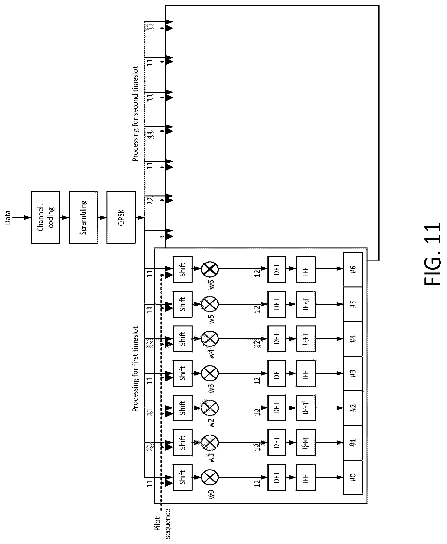
[0026] FIG. 11 illustrates an example implementation for transmitting a pilot sequence together with a channel-coded data sequence.
DETAILED DESCRIPTION OF ILLUSTRATIVE EMBODIMENTS
[0027] A detailed description of illustrative embodiments will now be described with reference to the various Figures. Although this description provides a detailed example of possible implementations, it should be noted that the details are intended to be exemplary and in no way limit the scope of the application.
[0028] FIG. 1A is a diagram of an example communications system 100 in which one or more disclosed embodiments may be implemented. The communications system 100 may be a multiple access system that provides content, such as voice, data, video, messaging, broadcast, etc., to multiple wireless users. The communications system 100 may enable multiple wireless users to access such content through the sharing of system resources, including wireless bandwidth. For example, the communications systems 100 may employ one or more channel access methods, such as code division multiple access (CDMA), time division multiple access (TDMA), frequency division multiple access (FDMA), orthogonal FDMA (OFDMA), single-carrier FDMA (SC-FDMA), and the like.
[0029] As shown in FIG. 1A, the communications system 100 may include wireless transmit/receive units (WTRUs) 102a, 102b, 102c, and/or 102d (which generally or collectively may be referred to as WTRU 102), a radio access network (RAN) 104, a core network 107, a public switched telephone network (PSTN) 108, the Internet 110, and other networks 112, though it will be appreciated that the disclosed embodiments contemplate any number of WTRUs, base stations, networks, and/or network elements. Each of the WTRUs 102a, 102b, 102c, 102d may be any type of device configured to operate and/or communicate in a wireless environment. By way of example, the WTRUs 102a, 102b, 102c, 102d may be configured to transmit and/or receive wireless signals and may include user equipment (UE), a mobile station, a fixed or mobile subscriber unit, a pager, a cellular telephone, a personal digital assistant (PDA), a smartphone, a laptop, a netbook, a personal computer, a wireless sensor, consumer electronics, and the like.
[0030] The communications systems 100 may also include a base station 114a and a base station 114b. Each of the base stations 114a, 114b may be any type of device configured to wirelessly interface with at least one of the WTRUs 102a, 102b, 102c, 102d to facilitate access to one or more communication networks, such as the core network 107, the Internet 110, and/or the networks 112. By way of example, the base stations 114a, 114b may be a base transceiver station (BTS), a Node-B, an eNode B, a Home Node B, a Home eNode B, a site controller, an access point (AP), a wireless router, and the like. While the base stations 114a, 114b are each depicted as a single element, it will be appreciated that the base stations 114a, 114b may include any number of interconnected base stations and/or network elements.
[0031] The base station 114a may be part of the RAN 104, which may also include other base stations and/or network elements (not shown), such as a base station controller (BSC), a radio network controller (RNC), relay nodes, etc. The base station 114a and/or the base station 114b may be configured to transmit and/or receive wireless signals within a particular geographic region, which may be referred to as a cell (not shown). The cell may further be divided into cell sectors. For example, the cell associated with the base station 114a may be divided into three sectors. Thus, in one embodiment, the base station 114a may include three transceivers, i.e., one for each sector of the cell. In another embodiment, the base station 114a may employ multiple-input multiple output (MIMO) technology and, therefore, may utilize multiple transceivers for each sector of the cell.
[0032] The base stations 114a, 114b may communicate with one or more of the WTRUs 102a, 102b, 102c, 102d over an air interface 116, which may be any suitable wireless communication link (e.g., radio frequency (RF), microwave, infrared (IR), ultraviolet (UV), visible light, etc.). The air interface 116 may be established using any suitable radio access technology (RAT).
[0033] More specifically, as noted above, the communications system 100 may be a multiple access system and may employ one or more channel access schemes, such as CDMA, TDMA, FDMA, OFDMA, SC-FDMA, and the like. For example, the base station 114a in the RAN 104 and the WTRUs 102a, 102b, 102c may implement a radio technology such as Universal Mobile Telecommunications System (UMTS) Terrestrial Radio Access (UTRA), which may establish the air interface 116 using wideband CDMA (WCDMA). WCDMA may include communication protocols such as High-Speed Packet Access (HSPA) and/or Evolved HSPA (HSPA+). HSPA may include High-Speed Downlink Packet Access (HSDPA) and/or High-Speed Uplink Packet Access (HSUPA).
[0034] In another embodiment, the base station 114a and the WTRUs 102a, 102b, 102c may implement a radio technology such as Evolved UMTS Terrestrial Radio Access (E-UTRA), which may establish the air interface 116 using Long Term Evolution (LTE) and/or LTE-Advanced (LTE-A).
[0035] In other embodiments, the base station 114a and the WTRUs 102a, 102b, 102c may implement radio technologies such as IEEE 802.16 (i.e., Worldwide Interoperability for Microwave Access (WiMAX)), CDMA2000, CDMA2000 1.times., CDMA2000 EV-DO, Interim Standard 2000 (IS-2000), Interim Standard 95 (IS-95), Interim Standard 856 (IS-856), Global System for Mobile communications (GSM), Enhanced Data rates for GSM Evolution (EDGE), GSM EDGE (GERAN), and the like.
[0036] The base station 114b in FIG. 1A may be a wireless router, Home Node B, Home eNode B, or access point, for example, and may utilize any suitable RAT for facilitating wireless connectivity in a localized area, such as a place of business, a home, a vehicle, a campus, and the like. In one embodiment, the base station 114b and the WTRUs 102c, 102d may implement a radio technology such as IEEE 802.11 to establish a wireless local area network (WLAN). In another embodiment, the base station 114b and the WTRUs 102c, 102d may implement a radio technology such as IEEE 802.15 to establish a wireless personal area network (WPAN). In yet another embodiment, the base station 114b and the WTRUs 102c, 102d may utilize a cellular-based RAT (e.g., WCDMA, CDMA2000, GSM, LTE, LTE-A, etc.) to establish a picocell or femtocell. As shown in FIG. 1A, the base station 114b may have a direct connection to the Internet 110. Thus, the base station 114b may not be required to access the Internet 110 via the core network 107.
[0037] The RAN 104 may be in communication with the core network 107, which may be any type of network configured to provide voice, data, applications, and/or voice over internet protocol (VoIP) services to one or more of the WTRUs 102a, 102b, 102c, 102d. For example, the core network 107 may provide call control, billing services, mobile location-based services, pre-paid calling, Internet connectivity, video distribution, etc., and/or perform high-level security functions, such as user authentication. Although not shown in FIG. 1A, it will be appreciated that the RAN 104 and/or the core network 107 may be in direct or indirect communication with other RANs that employ the same RAT as the RAN 104 or a different RAT. For example, in addition to being connected to the RAN 104, which may be utilizing an E-UTRA radio technology, the core network 107 may also be in communication with another RAN (not shown) employing a GSM radio technology.
[0038] The core network 107 may also serve as a gateway for the WTRUs 102a, 102b, 102c, 102d to access the PSTN 108, the Internet 110, and/or other networks 112. The PSTN 108 may include circuit-switched telephone networks that provide plain old telephone service (POTS). The Internet 110 may include a global system of interconnected computer networks and devices that use common communication protocols, such as the transmission control protocol (TCP), user datagram protocol (UDP) and the internet protocol (IP) in the TCP/IP internet protocol suite. The networks 112 may include wired or wireless communications networks owned and/or operated by other service providers. For example, the networks 112 may include another core network connected to one or more RANs, which may employ the same RAT as the RAN 104 or a different RAT.
[0039] Some or all of the WTRUs 102a, 102b, 102c, 102d in the communications system 100 may include multi-mode capabilities, i.e., the WTRUs 102a, 102b, 102c, 102d may include multiple transceivers for communicating with different wireless networks over different wireless links. For example, the WTRU 102c shown in FIG. 1A may be configured to communicate with the base station 114a, which may employ a cellular-based radio technology, and with the base station 114b, which may employ an IEEE 802 radio technology.
[0040] FIG. 1B is a system diagram of an example WTRU 102. As shown in FIG. 1B, the WTRU 102 may include a processor 118, a transceiver 120, a transmit/receive element 122, a speaker/microphone 124, a keypad 126, a display/touchpad 128, non-removable memory 130, removable memory 132, a power source 134, a global positioning system (GPS) chipset 136, and other peripherals 138. It will be appreciated that the WTRU 102 may include any sub-combination of the foregoing elements while remaining consistent with an embodiment. Also, embodiments contemplate that the base stations 114a and 114b, and/or the nodes that base stations 114a and 114b may represent, such as but not limited to transceiver station (BTS), a Node-B, a site controller, an access point (AP), a home node-B, an evolved home node-B (eNodeB), a home evolved node-B (HeNB), a home evolved node-B gateway, and proxy nodes, among others, may include some or all of the elements depicted in FIG. 1B and described herein.
[0041] The processor 118 may be a general purpose processor, a special purpose processor, a conventional processor, a digital signal processor (DSP), a plurality of microprocessors, one or more microprocessors in association with a DSP core, a controller, a microcontroller, Application Specific Integrated Circuits (ASICs), Field Programmable Gate Array (FPGAs) circuits, any other type of integrated circuit (IC), a state machine, and the like. The processor 118 may perform signal coding, data processing, power control, input/output processing, and/or any other functionality that enables the WTRU 102 to operate in a wireless environment. The processor 118 may be coupled to the transceiver 120, which may be coupled to the transmit/receive element 122. While FIG. 1B depicts the processor 118 and the transceiver 120 as separate components, it will be appreciated that the processor 118 and the transceiver 120 may be integrated together in an electronic package or chip.
[0042] The transmit/receive element 122 may be configured to transmit signals to, or receive signals from, a base station (e.g., the base station 114a) over the air interface 116. For example, in one embodiment, the transmit/receive element 122 may be an antenna configured to transmit and/or receive RF signals. In another embodiment, the transmit/receive element 122 may be an emitter/detector configured to transmit and/or receive IR, UV, or visible light signals, for example. In yet another embodiment, the transmit/receive element 122 may be configured to transmit and receive both RF and light signals. It will be appreciated that the transmit/receive element 122 may be configured to transmit and/or receive any combination of wireless signals.
[0043] In addition, although the transmit/receive element 122 is depicted in FIG. 1B as a single element, the WTRU 102 may include any number of transmit/receive elements 122. More specifically, the WTRU 102 may employ MIMO technology. Thus, in one embodiment, the WTRU 102 may include two or more transmit/receive elements 122 (e.g., multiple antennas) for transmitting and receiving wireless signals over the air interface 116.
[0044] The transceiver 120 may be configured to modulate the signals that are to be transmitted by the transmit/receive element 122 and to demodulate the signals that are received by the transmit/receive element 122. As noted above, the WTRU 102 may have multi-mode capabilities. Thus, the transceiver 120 may include multiple transceivers for enabling the WTRU 102 to communicate via multiple RATs, such as UTRA and IEEE 802.11, for example.
[0045] The processor 118 of the WTRU 102 may be coupled to, and may receive user input data from, the speaker/microphone 124, the keypad 126, and/or the display/touchpad 128 (e.g., a liquid crystal display (LCD) display unit or organic light-emitting diode (OLED) display unit). The processor 118 may also output user data to the speaker/microphone 124, the keypad 126, and/or the display/touchpad 128. In addition, the processor 118 may access information from, and store data in, any type of suitable memory, such as the non-removable memory 130 and/or the removable memory 132. The non-removable memory 130 may include random-access memory (RAM), read-only memory (ROM), a hard disk, or any other type of memory storage device. The removable memory 132 may include a subscriber identity module (SIM) card, a memory stick, a secure digital (SD) memory card, and the like. In other embodiments, the processor 118 may access information from, and store data in, memory that is not physically located on the WTRU 102, such as on a server or a home computer (not shown).
[0046] The processor 118 may receive power from the power source 134, and may be configured to distribute and/or control the power to the other components in the WTRU 102. The power source 134 may be any suitable device for powering the WTRU 102. For example, the power source 134 may include one or more dry cell batteries (e.g., nickel-cadmium (NiCd), nickel-zinc (NiZn), nickel metal hydride (NiMH), lithium-ion (Li-ion), etc.), solar cells, fuel cells, and the like.
[0047] The processor 118 may also be coupled to the GPS chipset 136, which may be configured to provide location information (e.g., longitude and latitude) regarding the current location of the WTRU 102. In addition to, or in lieu of, the information from the GPS chipset 136, the WTRU 102 may receive location information over the air interface 116 from a base station (e.g., base stations 114a, 114b) and/or determine its location based on the timing of the signals being received from two or more nearby base stations. It will be appreciated that the WTRU 102 may acquire location information by way of any suitable location-determination method while remaining consistent with an embodiment.
[0048] The processor 118 may further be coupled to other peripherals 138, which may include one or more software and/or hardware modules that provide additional features, functionality and/or wired or wireless connectivity. For example, the peripherals 138 may include an accelerometer, an e-compass, a satellite transceiver, a digital camera (for photographs or video), a universal serial bus (USB) port, a vibration device, a television transceiver, a hands free headset, a Bluetooth.RTM. module, a frequency modulated (FM) radio unit, a digital music player, a media player, a video game player module, an Internet browser, and the like.
[0049] FIG. 1C is a system diagram of the RAN 104 and the core network 107 according to an embodiment. As noted above, the RAN 104 may employ an E-UTRA radio technology to communicate with the WTRUs 102a, 102b, 102c over the air interface 116. The RAN 104 may also be in communication with the core network 107.
[0050] The RAN 104 may include eNode-Bs 160a, 160b, 160c, though it will be appreciated that the RAN 104 may include any number of eNode-Bs while remaining consistent with an embodiment. The eNode-Bs 160a, 160b, 160c may each include one or more transceivers for communicating with the WTRUs 102a, 102b, 102c over the air interface 116. In one embodiment, the eNode-Bs 160a, 160b, 160c may implement MIMO technology. Thus, the eNode-B 160a, for example, may use multiple antennas to transmit wireless signals to, and receive wireless signals from, the WTRU 102a.
[0051] Each of the eNode-Bs 160a, 160b, 160c may be associated with a particular cell (not shown) and may be configured to handle radio resource management decisions, handover decisions, scheduling of users in the uplink and/or downlink, and the like. As shown in FIG. 1C, the eNode-Bs 160a, 160b, 160c may communicate with one another over an X2 interface.
[0052] The core network 107 shown in FIG. 1C may include a mobility management gateway (MME) 162, a serving gateway 164, and a packet data network (PDN) gateway 166. While each of the foregoing elements are depicted as part of the core network 107, it will be appreciated that any one of these elements may be owned and/or operated by an entity other than the core network operator.
[0053] The MME 162 may be connected to each of the eNode-Bs 160a, 160b, 160c in the RAN 104 via an Si interface and may serve as a control node. For example, the MME 162 may be responsible for authenticating users of the WTRUs 102a, 102b, 102c, bearer activation/deactivation, selecting a particular serving gateway during an initial attach of the WTRUs 102a, 102b, 102c, and the like. The MME 162 may also provide a control plane function for switching between the RAN 104 and other RANs (not shown) that employ other radio technologies, such as GSM or WCDMA.
[0054] The serving gateway 164 may be connected to each of the eNode-Bs 160a, 160b, 160c in the RAN 104 via the Si interface. The serving gateway 164 may generally route and forward user data packets to/from the WTRUs 102a, 102b, 102c. The serving gateway 164 may also perform other functions, such as anchoring user planes during inter-eNode B handovers, triggering paging when downlink data is available for the WTRUs 102a, 102b, 102c, managing and storing contexts of the WTRUs 102a, 102b, 102c, and the like.
[0055] The serving gateway 164 may also be connected to the PDN gateway 166, which may provide the WTRUs 102a, 102b, 102c with access to packet-switched networks, such as the Internet 110, to facilitate communications between the WTRUs 102a, 102b, 102c and IP-enabled devices.
[0056] The core network 107 may facilitate communications with other networks. For example, the core network 107 may provide the WTRUs 102a, 102b, 102c with access to circuit-switched networks, such as the PSTN 108, to facilitate communications between the WTRUs 102a, 102b, 102c and traditional land-line communications devices. For example, the core network 107 may include, or may communicate with, an IP gateway (e.g., an IP multimedia subsystem (IMS) server) that serves as an interface between the core network 107 and the PSTN 108. In addition, the core network 107 may provide the WTRUs 102a, 102b, 102c with access to the networks 112, which may include other wired or wireless networks that are owned and/or operated by other service providers.
[0057] Typically, a VoIP packet from the speech codec arrives for transmission about every 20 ms. Given the small payload of such speech packets (e.g., on the order of 30-40 bytes or less including protocol overhead), every such voice packet may in principle be sent as a single transport block (TB) in a single subframe. When HARQ re-transmissions and TTI bundling are not used, sending each voice packet in a single TB in a single subframe may lead to a total of 5% UL transmission activity. In other words, there would be a single VoIP packet coded in the form of a single new TB mapped to a single subframe every 20 ms.
[0058] Several techniques may be pertinent when considering the achievable coverage for LTE radio access. For example, HARQ re-transmissions, TTI bundling, RLC segmentation, IP packet bundling, modification of reference signal scheduling, and/or one-way user-plane delays may be considered when designing a coverage scheme.
[0059] If HARQ re-transmissions are utilized, the amount of utilized WTRU UL transmission time may be increased both per voice packet and/or per WTRU. For an incoming VoIP packet mapped to 1 TB, typically up to 6 HARQ retransmissions may be allowed with a 50 ms UL Uu delay budget. Therefore, a VoIP packet may be transmitted up to a total of 7 times over the duration of the same 50 ms period, assuming the Release 8/10 LTE Maximum round trip time (RTT) of 8 subframes. Given that on average 2 or 3 concurrent VoIP packets, or 2 or 3 parallel HARQ processes are being transmitted in any given frame by the WTRU, the use of HARQ retransmissions may lead to an average of 30% UL transmission activity. In other words, on average 3 out of every 10 UL subframes may be used by the WTRU for VoIP transmission. Accordingly, UL coverage for a VoIP codec packet transmission in presence of HARQ may be nominally improved by a (linear) factor of 7 as compared to no HARQ. Such an improvement in subframe utilization may correspond to about 8.4 dB more energy collected per VoIP packet by the receiver, discounting for performance aspects in presence of real-life fading channels.
[0060] Release 8 LTE introduced the TTI bundling mode of operation to improve UL coverage. TTI bundling may be configured so as to proactively re-transmit data included in a given transport block prior to receiving any feedback regarding the reception of the TB. The TBs associated with the TTI bundle may be used to transmit the same data and/or different redundancy versions of the same data. TTI bundling may be designed to maximize the amount of time a WTRU may transmit continuously with maximum power.
[0061] In an example, TTI bundling may repeat the same data in multiple TTIs. For example, LTE Release 8 may specify a TTI bundle size of 4; however, Release 8 LTE does not specify other possible bundle sizes. The achievable UL performance may be increased when employing physical uplink shared channel (PUSCH) bundle sizes of both 4 and 8. For example, a single TB may be channel coded and transmitted in a set of 4 consecutive TTIs. The bundled TTIs may be treated as a single resource, for example by utilizing a single UL grant and a single physical HARQ indicator channel (PHICH) ACK/NACK for the entire bundle. TTI bundling in Release 8/10 LTE may be activated through radio resource control (RRC) signaling. For example, a evolved Node B (eNB) may observe WTRU transmissions and determine a WTRU pathloss. If the WTRU pathloss exceeds a critical value and/or predetermined threshold, the eNB may activate TTI bundling.
[0062] If Release 8/10 HARQ is utilized but TTI bundling is not, a VoIP codec packet including its protocol overhead may typically result in up to 7 TTIs with the existing LTE n+4 HARQ timelines. When Release 8/10 TTI bundling is used, a VoIP packet may be transmitted using a bundle of 4 consecutive subframes. A TTI bundling pattern may repeat in periods of 16 subframes. For example, for the same 50 ms UL Uu delay budget, 12 subframes (or 3 patterns that are each 16 subframes long and contain 4 TTIs) may be received by the receiver. Therefore, TTI bundling may result in a coverage boost of approximately 2.3 dB (e.g., 10*log 10(12/7)) due to an increase in the collection of energy by the decoder. Second order impacts such as burst error rates (e.g., the probability of the entire bundle in four consecutive TTIs being lost versus probability of a single TTI being lost) may be considered when designing a system with increased coverage. For example, transmission errors may often occur in bursts, so increasing the bundle size from 4 to 8 while still keeping the pattern to 16 subframes may result in an additional 1 dB improvement, but perhaps not much more than that if errors occur in bursts.
[0063] The Release 8/10 LTE RLC protocol may perform segmentation and/or concatenation of higher layer PDUs. One approach to improve LTE UL coverage may be to segment RLC SDUs (e.g., VoIP codec packets including compressed IP and above headers) into several smaller units. For example, a stronger modulation and coding scheme (MCS) may be selected when channel coding each of the TBs that corresponds to the smaller/segmented PDUs. By doing so, it may be more likely that the resulting smaller TBs will be decoded correctly. Given that the resulting number of concurrently used running HARQ processes may increase when compared to the case where RLC segmentation is not utilized, the effective UL subframe utilization and/or UL transmission activity may be increased.
[0064] The performance and drawbacks when segmenting VOIP codec packets (e.g., RLC PDUs/SDUs) into smaller RLC PDUs/SDUs to improve UL coverage may be compared. The resulting overhead from creating smaller RLC PDUs may begin to significantly impact the achievable gains in terms of the observable Eb/No improvement when the number of RLC segments per SDU is increased beyond 4. Another aspect to consider may be the reduction of the number of available retransmissions per HARQ process on a per PDU basis. A new SDU is typically transmitted every 20 ms. This may result in N segmented PDUs occupying N HARQ processes starting every 20 ms. Each of these HARQ processes may remain active during the allowed 50 ms one-way Uu delay budget. In Release 8/10 LTE, since a single HARQ process per subframe or a single TB transmission per subframe may be present, when subsequent SDUs arrive for transmission, UL subframe utilization may become a limiting factor because the previous HARQ processes may still be transmitting retransmissions. Using RLC segmentation, there may be a trade-off between the number of HARQ retransmissions per RLC PDU and the number of concurrent HARQ processes. Note that when RLC segmentation is used together with TTI bundling, typically no more than two RLC PDUs per SDU may be accommodated, typically resulting in four or less active HARQ processes when TTI bundling is used.
[0065] For example, DL IP packet bundling may be a technique that is designed to trade-off single user transmission efficiency against system capacity in LTE systems. IP packet bundling may be the operation of bundling multiple VoIP packets together for 1 single transmission in a subframe. Such VoIP packet bundling may be channel quality indicator (CQI) based. For example, VoIP packet bundling may be applied to users which are deemed by the eNB to be in favorable channel conditions. Because bundled VoIP packets may be subject to tighter allowed one-way Uu delay budgets, on average fewer HARQ retransmissions may be used. There may be an achievable DL performance increase when aggregating 2 VoIP packets at the codec (e.g., IP or above) layer into a single TB. For example, the increased TB sizes when aggregating 2 IP packets may not result in a significant coverage loss. However, the lack of coverage loss may be attributed to the much higher available eNB Tx power for the DL. Because of UL Tx power limitations and the principle of non-CQI based UL scheduling in LTE, IP packet bundling may not be as effective of a technique for UL coverage improvements as for DL coverage improvement.
[0066] Existing Release 8/9/10 transmission schemes for the Physical Uplink Control Channel (PUCCH) and the Physical Uplink Shared Channel (PUSCH) may offer limited flexibility in terms of the configuring which resources (e.g., resource elements) include user and/or control data versus which resources include pilot signals. For example, the PUSCH may include one pilot symbol at the center of each timeslot while other transmission schemes, such as PUCCH Format 3, may include two pilot symbols per timeslot. For instance, PUCCH Format 3 may include a pilot signal on symbols #2 and #6 of each timeslot. In existing Release 8/9/10 transmission schemes, the location of the pilot signals may be predetermined, and hence a WTRU may be unable to vary the position of the pilot signals based on link and/or channel conditions. Additionally, due to the several design considerations for these transmission schemes, PUCCH transmissions may be performed in accordance with a frequency hopping scheme. For example, the frequency hopping scheme may be performed across the UL system bandwidth over the two timeslots in a subframe. Moreover, PUSCH spatial multiplexing and/or frequency-domain scheduling gains have led to pilot signal designs such that the transmitted pilot signals are orthogonal between WTRUs transmitting on the same resource blocks. Modification of such a scheme may allow for improved link coverage, but may affect other aspects of UL system design.
[0067] To further increase UL coverage, the WTRU and/or eNB may be configured to adjust the allowed one-way UL Uu delay budget for a transmitted packet. For example, typically a 50 ms air interface delays is deemed to be acceptable for UL transmission. The UL Uu interface delay may be a portion of the overall ear-to-mouth VoIP delay, for example along with WTRU and eNB processing times, codec delays, interface signaling durations, and/or other delay sources. Allowing for longer air interface delays may allow for more energy to be collected from each VoIP packet during the lifetime of the HARQ process. In other words, more re-transmissions may be used, increasing the likelihood of a successful decoding.
[0068] However, increasing the allowed one-way UL delays over the air interface may result in one or more trade-offs with other aspects of the system design. To illustrate such a tradeoff, consider an example where the allowable UL transmission delays are increased from a typical value of about 50 ms to a value such as 70 ms. In the presence of TTI bundling, such a change may allow up to 20 TTIs to be used for transmission of a packet instead of a typical maximum of 12. The resulting increased combining gains may result in higher UL coverage. However, the mouth-to-ear delay for voice typically should not exceed 280 ms to ensure a minimum level of voice quality. For increased voice quality, typical end-to-end delays of the order of approximately 200 ms or less may be used to achieve a suitable voice quality. Thus, there may be limited flexibility in allowing the maximum air interface delay to increase while still maintaining the 280 ms mouth-to-ear delay time. In existing wireless systems including LTE, the portion allocated to Uu one-way delays is typically in the order of 50 ms (the remainder being absorbed by network and processing delays). Therefore, in practice the typical 50 ms delay budget numbers may be increased to delay values of the order of 60 or 70 ms for limited gain, but not much beyond such values if the mouth-to-ear delay is to be met according to current processing techniques.
[0069] A number of techniques, methods, and systems are disclose herein to improve the reception of UL transmission in noise-limited and/or power limited scenarios. These methods are designed to increase the available signal energy and/or making more efficient use of the available signal energy at the receiver for processing UL transmissions. The proposed methods and systems described herein may be applied individually or in any combination.
[0070] In order to limit the applicability of one or more of the methods or systems described herein to WTRUs that are most likely to experience uplink coverage problems (e.g., thereby allowing WTRUs that are not affected by adverse UL conditions to utilize legacy UL transmission techniques), the methods and systems described herein may be applied when a WTRU enters or operates in a "Coverage Limited Mode" or a "Power Limited Mode." In these modes, the WTRU may be configured to implement one or more of methods or systems described herein to improve link coverage. In an example, WTRUs that are not in a "Coverage Limited Mode" or a "Power Limited Mode" (e.g., "Normal Mode") may operate according to existing LTE Release 8 or Release 10 UL transmission specifications.
[0071] A WTRU that is operating in "Normal Mode" may be triggered to transition to "Coverage Limited Mode" by an eNB, for example using RRC signaling. In an example, the WTRU may be configured by an eNB for operation in "Normal Mode" and "Coverage Limited Mode" through RRC signaling and the WTRU may determine the appropriate mode of operation for a given time instance based on observed conditions and/or indications received from the eNB. For example, the mode of operation (e.g., "Normal" vs. "Coverage Limited") may be configured dynamically by the eNB by the transmission of a MAC Control Element that indicates a specific mode or operation and/or indicates to the WTRU that it should toggle between modes (e.g., switch from its current mode to the other mode). The determination by the eNB to change the mode of operation of a WTRU may be based on, but not limited to, UL power headroom (UPH) measurement reports from the WTRU and/or a request from a WTRU to change from "Normal Mode" to "Coverage Limited Mode." In an example, the WTRU may autonomously determine which mode of operation to use for UL transmission, (e.g., "Normal Mode" or "Coverage Limited Mode"). The determination UL mode may be based on UPH or other measurements.
[0072] However, the methods and systems described herein for improving UL coverage may be applicable to WTRUs that are operating under normal radio coverage conditions. For example, many of the methods and systems described herein (e.g., utilizing "fast HARQ" or HARQ with a shorter RTT, utilizing "long TTIs," utilizing dedicated PUSCH allocations, utilizing variations in reference signal design, utilizing different types of PUSCH modulation, utilizing multiple transmission schemes, utilizing multiple UL reception points, utilizing protocol overhead reduction techniques, and/or the like in any combination) may be incorporated into regular WTRU operation without explicit differentiation between a "Coverage Limited Mode" and a "Normal Mode." Therefore, any WTRU implementing one or more of the systems or methods described herein for improving UL coverage may be considered to be operating in "Coverage Limited Mode." In this sense, in some examples a WTRU may operate in a "Coverage Limited Mode" by implementing over or more of the UL coverage improvement techniques described herein (e.g., utilizing "fast HARQ" or HARQ with a shorter RTT, utilizing "long TTIs," utilizing dedicated PUSCH allocations, utilizing variations in reference signal design, utilizing different types of PUSCH modulation, utilizing multiple transmission schemes, utilizing multiple UL reception points, utilizing protocol overhead reduction techniques, and/or the like in any combination).
[0073] Thus, although one or more systems or methods described herein may be described with reference to operation in "Coverage Limited Mode" or "Power Limited Mode," these systems and methods may also be implemented in normal WTRU operation. Thus, the techniques described herein should not be read to be applicable only to WTRUs operating in a certain mode of operation unless specifically stated otherwise.
[0074] In an example, a WTRU may operate one or more (or all) HARQ processes with a shorter HARQ round trip time (RTT) (e.g., 4 subframes) than a default HARQ RTT (e.g., 8 subframes). For example, a WTRU in "Coverage Limited Mode" or "Power Limited Mode" may be configured to operate some or all HARQ processes using a shorter RTT. For example, methods may be defined to dynamically adjust the HARQ RTT for the one or more HARQ process(es) and/or to dynamically change the number of subframes used for transmission of a transport block (e.g., TBs that span multiple subframes may be used and/or the number of subframes used for transmission of a TB may be altered dynamically, for example based on channel conditions).
[0075] When referred to herein, the term HARQ process may exclude a HARQ process related to reception of system broadcasts (e.g., HARQ process may be used to refer for HARQ processes used for transmissions that are dedicated to the WTRU). Additionally, when referred to herein, the term "bundling" may be used to refer to a HARQ operation by which a HARQ entity may invoke the same HARQ process for each transmission that may be part of the same bundle. For example, when bundling is used, retransmissions within a bundle may be non-adaptive and may be triggered without waiting for feedback from previous transmissions according to the size of the bundled transmission. However, the methods described herein are not limited to such a type of bundling and may be equally applicable to other form of transmission over multiple subframes including when the transmission of a single transport block may be performed over a plurality of subframes. In such an embodiment, the bundle size may, for example, correspond to the transmission time for the transport block.
[0076] For a given HARQ process, a typical processing sequence may include the scheduling of the HARQ process, the transmission for the HARQ process, and/or reception of feedback for the HARQ process. For example, a WTRU may receive downlink control signaling that indicates a grant for an uplink resource (e.g., dynamic scheduling). For retransmissions, the WTRU may perform an autonomous synchronous HARQ retransmission without receiving any downlink control signaling for the concerned HARQ process. In case of semi-persistent scheduling (SPS), the WTRU may use the configured grant in the applicable subframe if the WTRU does not receive dynamic scheduling information for the corresponding HARQ process. Assigning HARQ resources either implicitly or explicitly for dynamic scheduling and SPS may be referred to as scheduling of the HARQ process(es).
[0077] A WTRU may perform a transmission on the PUSCH for a given HARQ process according to the allocated uplink resource. For example, the allocated uplink resource may be dynamically scheduled and/or configured with semi-persistent scheduling. In some situations, such as autonomous synchronous HARQ retransmissions, rather than the eNB allocating specific UL resources for a retransmission using a dynamic grant, the retransmission times/opportunities for HARQ may be based on implicit rules. Allocating resources for transmission/retransmission either explicitly or implicitly may be referred to as transmission for the HARQ process.
[0078] A WTRU may receive HARQ feedback on the PHICH, on the physical downlink control channel (PDCCH), and/or on both the PHICH and the PDCCH. The feedback may indicate whether the eNB successfully decoded a previous transmission corresponding to the applicable HARQ process. The feedback indication may be referred to as reception of feedback for the HARQ process.
[0079] In an example, the timing relationships between the scheduling of the HARQ process, transmission for the HARQ process, and reception of feedback for the HARQ process may be varied for a given HARQ process. As a reference and for purposes of explanation and illustration, the subframe that corresponds to an action that is a timing reference for some future action may be referred to as subframe (n). The following timing relationships and descriptors may be used throughout this document. For example, if grant reception may occurs in subframe (n), HARQ transmission may occur in subframe (n+x) (e.g., the HARQ transmission/data transmission may occur x subframes that the grant is received). Thus, the subframe utilized for HARQ transmission may be referred to as n+x. In another example, if the HARQ transmission occurs in subframe (n), then HARQ feedback reception may occur in subframe (n+k) (e.g., the HARQ feedback may be received k subframes after the HARQ transmission associated with the received HARQ feedback was transmitted). The subframe utilized for HARQ feedback may be referred to as n+k. In another example, if HARQ feedback occurs in subframe (n), the WTRU-autonomous synchronous HARQ retransmission may occur in subframe (n+y) (e.g., a HARQ retransmission may occur y subframes after a NACK is received). The subframe used for WTRU-autonomous synchronous HARQ retransmission may be referred to as n+y.
[0080] In the examples included herein, unless n+y is used explicitly, the timing delay from HARQ transmission to HARQ feedback may be equivalent or equal to that from HARQ feedback reception to a HARQ retransmission (e.g., represented by n+x). In other words, the corresponding timing of a subframe used for WTRU-autonomous synchronous HARQ retransmission may coincide with the subframe in which a WTRU may possibly receive a dynamic scheduling for the concerned HARQ process.
[0081] In an example, the HARQ RTT for a given HARQ process may be further generalized as the minimum number of subframes that may be utilized and/or needed for a HARQ process to receive downlink control information that schedules the HARQ process, to perform the transmission x subframes later, and to receive HARQ feedback x subframes after the transmission. When TTI bundling is used, the timing of the HARQ feedback may implicitly also include the length of the bundle in subframes. For example, for a bundle of TTI_BUNDLE_SIZE (e.g., TTI_BUNDLE_SIZE=4), the timing of the HARQ feedback may be adjusted such that it may be TTI_BUNDLE_SIZE-1 (e.g., 3) subframes later than if bundling is not used for the transmission. In an example embodiment, TTI_BUNDLE_SIZE may vary from one transmission to another, for example based on various transmission parameters and channel conditions. For LTE Release 8, x=k=4 and the HARQ RTT may therefore be 8 subframes. As such, x=k=4 and a HARQ RTT of 8 subframes may be referred to herein as the default HARQ values.
[0082] The Maximum HARQ RTT for a given HARQ entity may be equal to the HARQ RTT of the HARQ process that has the largest value for x+k. For example, if all HARQ processes for a given HARQ entity (and/or the WTRU) operate with x=k=2, then the Maximum HARQ RTT may be 4 subframes. As another example, if two HARQ processes operate with x=k=2, and a third HARQ processes operates using the default values, then the Maximum HARQ RTT for the HARQ entity may be 8 subframes. Thus the Maximum HARQ RTT for a given HARQ entity may be the maximum or largest possible HARQ RTT for any of the HARQ processes served by that HARQ entity. Thus, if the default values are used, the Maximum HARQ RTT may correspond to a HARQ RTT of 8 subframes.
[0083] The maximum number of active HARQ processes for WTRU and/or for a given HARQ entity may be equal to the number of HARQ processes that are available for an initial uplink transmission within the Maximum HARQ RTT. For example, if all HARQ processes operate with x=k=2, then the WTRU may perform uplink transmissions using up to four different HARQ processes of the HARQ entity during a given HARQ RTT. For example, the WTRU may perform up to 2 transmissions per HARQ process during the default HARQ RTT of 8 subframes. HARQ processes that are not be addressed may be suspended, stopped, and/or flushed.
[0084] As an example, if two HARQ processes operate with x=k=2 while the others operate with the default values x=k=4, then the WTRU may perform uplink transmissions using up to six different HARQ processes of the HARQ entity during a given HARQ RTT. In this example, the WTRU may perform up to 2 transmissions for the processes using x=k=2, while performing at most one for the other processes during the default HARQ RTT of 8 subframes.
[0085] A WTRU may assign a HARQ process identity (ID) for a HARQ process when the WTRU performs a new transmission. For example, if synchronous HARQ is used, the WTRU may assign an identity to the HARQ process that is linked to the timing of the subframe. For example, the WTRU may assign HARQ process ID=n to a HARQ process that is associated with an initial transmission in subframe(n). Then, HARQ process n may be used for other initial transmissions that occur in subframes that are some integer multiple of x+k subframes after subframe(n) (e.g., subframe(n+(x+k)), subframe(n+2(x+k)), subframe(n+2(x+k)), etc.). beginning with the subframe in which the WTRU performed the initial transmission for the HARQ process (e.g., subframe(n)). For example, if the WTRU operates with x=k=2 for all HARQ processes of a given HARQ entity, then according to the above, the HARQ RTT for all of HARQ processes may be equal to the Maximum HARQ RTT (e.g., 4 subframes). Thus, if x=k=2 and HARQ process n is associated with an initial transmission in subframe(n), then HARQ process n may also be used for transmissions occurring in subframe(n+4), subframe(n+8), subframe(n+12), etc. In this example, there may be up to 4 HARQ processes that may be addressed in a given RTT. Therefore, in an example the HARQ processes IDs may range from 0 to 3.
[0086] FIG. 2 illustrates an example of HARQ process operation for a HARQ entity where the WTRU operates with x=k=2 for a HARQ process of the HARQ entity. As illustrated in FIG. 2, during subframe(0) of Radio Frame i, the WTRU may receive Grant 202, for example via the PDCCH, which may be a grant of UL resources. Since x=2, in subframe(2), the WTRU may transmit and UL Transmission 204 on the PUSCH in the resources assigned by Grant 202. In subframe(4), the eNB may send HARQ Acknowledgement/Non-acknowledgement (A/N) Feedback 206 to the WTRU, for example via the PHICH. HARQ A/N Feedback 206 may indicate whether or not the eNB successfully received UL Transmission 204. If HARQ A/N Feedback 206 indicates that UL Transmission 204 was not successfully received, then in subframe(6), the WTRU may send UL Retransmission 208. In an example, if HARQ A/N Feedback 206 had indicated that the eNB had successfully received UL Transmission 204, the subframe(4) may have included a subsequent UL grant for subframe(6) (e.g., not illustrated in FIG. 2). In this example, the same HARQ process used for UL Transmission 204 could have been used for the new UL transmission in subframe(6); however, since HARQ A/N Feedback 206 indicated a negative acknowledgement, the HARQ process is used to send a UL Retransmission 208 in subframe (6), which may be an retransmission of UL Transmission 204. Similarly, in subframe(8), the eNB may send HARQ A/N Feedback 210 to the WTRU, for example via the PHICH, to indicate whether or not the eNB successfully received UL Retransmission 208 (e.g., whether the eNB was able to successfully combine UL Retransmission 208 and UL Transmission 204 to decode the UL data). If HARQ A/N Feedback 210 indicates that the eNB was still not able to successfully decode the UL date, then in subframe(0) for the next Radio Frame (e.g., Radio Frame i+1), the WTRU may send UL Retransmission 212. Each of the UL transmissions illustrated in FIG. 2 may be associated with the same HARQ process.
[0087] As another example, for a given HARQ entity the WTRU may operate with two HARQ processes with x=k=2, where a first HARQ process ID for a first process may corresponds to n=0 and a second HARQ process ID for a second process may corresponds to n=4. The remaining HARQ processes may operate with x=k=4. Therefore for this HARQ entity, the Maximum HARQ RTT may be 8 subframes, the maximum number of active HARQ processes may 6 processes, the HARQ processes IDs may range from 0 to 5, HARQ processes #0 and #3 may use a 4 ms RTT, and HARQ processes #1, #2, #4, and #5 may use an 8 ms RTT. FIG. 3 illustrates an example of HARQ process operation using a similar case, illustrating operation with one HARQ process with x=k=2 (e.g., HARQ Process #1), while other processes may operate with x=k=4 (e.g., HARQ Process #0 and HARQ Process #3).
[0088] For example, as illustrated in FIG. 3, during subframe(0) of Radio Frame i, the WTRU may perform UL transmission 302, which may be associated with HARQ process #0. At subframe(1), the WTRU may perform UL Transmission 304, which may be associated with HARQ process #1. At subframe(3), the WTRU may perform UL transmission 306, which may be associated with HARQ process #3. Additionally, during subframe(3) the WTRU may receive HARQ A/N Feedback 308, which may provide HARQ feedback for UL Transmission 304 corresponding to HARQ process #1. During subframe(4), the WTRU may receive HARQ A/N Feedback 310, which may provide HARQ feedback for UL Transmission 302 corresponding to HARQ process #0. At subframe(5), the WTRU may send UL Transmission 312 using HARQ process #1. UL Transmission 312 may be a new initial transmission if HARQ A/N Feedback 308 indicated that UL Transmission 304 was successfully received or may be a retransmission of UL Transmission 304 is HARQ A/N Feedback 308 indicates that UL Transmission 304 was not successfully received. During subframe(7), the WTRU may receive HARQ A/N Feedback 314, which may provide HARQ feedback for UL Transmission 312 corresponding to HARQ process #1, and may also receive HARQ A/N Feedback 316, which may provide HARQ feedback for UL Transmission 306 corresponding to HARQ process #3. Similar transmissions may continue where transmissions associated with HARQ process #1 utilize a RTT=4 ms subframes and x=k=2 and where transmissions associated with HARQ process #0 and/or HARQ Process #3 utilize a RTT=8 ms subframes and x=k=4.
[0089] In an example, the WTRU may retransmit the same transport block using a second HARQ process that follows a first HARQ process by x+k subframes (e.g., possibly increasing redundancy version) when x+k is smaller than the default value. This may be conceptually similar to using a single HARQ process that is active every x+k subframes, but would maintain the same number of active HARQ processes as for the default operation.
[0090] As an example, for a given HARQ entity the WTRU may operate with two HARQ processes, each with x=2, k=3, and configured with TTI bundling of 3 repetitions (e.g., TTI_BUNDLE_SIZE=4). Accordingly, for the concerned HARQ entity the maximum HARQ RTT may be 8 subframes (e.g., x+k+(TTI_BUNDLE_SIZE-1)=2+3+(4-1)=8), the maximum number of active HARQ processes may 2 processes (and/or 2 times 4 processes of which the last 3 perform retransmission of the same transport block for each bundle), the HARQ processes identity may range from 0 to 1, and the HARQ processes #0 and #1 may use a 8 ms RTT. FIG. 4 illustrates the operation of a single process in this case, where process #0 may start in subframe #2 of the first radio frame (and process #1, although not shown in FIG. 4, may start in subframe #6 of the same radio frame).
[0091] As shown in FIG. 4, an LTE TTI bundling mode (e.g., a TTI bundling size 4 is illustrated in FIG. 4) may now use a shorter A/N timeline of n+2/n+3. For example, at subframe(0), the WTRU may receive UL Grant 402. Two subframes later (e.g., x=2), the WTRU may begin transmitting data according to the received grant. Thus, starting at subframe(2), the WTRU may transmit UL Transmissions 404, which may be a TTI Bundled transmission with TTI_BUNDLE_SIZE=4. For a bundled transmission in this example, assuming the UL grant is received in subframe(n), then the WTRU may transmit the TB first in subframe(n+2), and then retransmit the same TB in subframe(n+3), subframe(n+4), and subframe(n+5) (e.g., n=2 for the example shown in FIG. 4). A corresponding PHICH A/N Transmission 406 may occur in subframe (n+8) (e.g., 3 subframes delay), followed by a re-transmission of the bundle via UL Transmissions 408, which may start in subframe(n+10) (e.g., 2 subframe delay) with retransmissions occurring in subframe(n+11), subframe(n+12), and subframe(n+13).
[0092] More generally, if the bundle size may be dynamically adapted, assuming that the a bundle transmission begins in subframe(b), then the bundle may be transmitted in subframes [b, b+(TTI_BUNDLE_SIZE-1)], for example, inclusively. The corresponding PHICH for the bundle may occur in subframe(b+(TTI_BUNDLE_SIZE-1)+k), followed by a retransmission of the bundle (e.g., if a negative acknowledgement is received) begging in subframe (b+(TTI_BUNDLE_SIZE-1)+k+y). For the retransmission, if the bundle size may be dynamically adapted, a different bundle size may be used for the retransmission (e.g., a TTI_BUNDLE_SIZE different than 4 may be used after receiving a negative acknowledgement via the PHICH).
[0093] The relationships expressed above may also be expressed relative to a UL grant that is received in subframe(n). For example, assuming that x=y=2, k=3 and TTI_BUNDLE_SIZE=4 (e.g., as illustrated in FIG. 4), then if the original UL grant is received in subframe(n), then since x=2 and TTI_BUNDLE_SIZE=4, the UL bundled transmissions may occur in subframes[(n+x), (n+x)+(TTI_BUNDLE_SIZE-1)] (e.g., subframe(n+2), subframe(n+3), subframe(n+4), and subframe(n+5), where n=0 for the example illustrated in FIG. 4). The A/N transmission for the bundle may then be received by the WTRU in subframe((n+x)+(TTI_BUNDLE_SIZE-1)+k), which may correspond to subframe((0+2)+(4-1)+3))=subframe(8). If the A/N indicted that the eNB did not successfully receive the TB transmitted in the bundle, then at subframe((n+x)+(TTI_BUNDLE_SIZE-1)+k+y)=subframe((0+2)+(4-1)+3+2))=subfra- me(10)=subframe(0) of the next radio frame, the WTRU may begin retransmission of the bundle (e.g., using the same or a different TTI_BUNDLE_SIZE). As may be appreciated, since there may be 10 subframes per radio frame in LTE, if a second HARQ event (e.g., UL grant, HARQ transmission, A/N transmission, HARQ retransmission, etc.) is configured to occur 10 subframes after a first HARQ event (e.g., UL grant, HARQ transmission, A/N transmission, HARQ retransmission, etc.), then the second HARQ event may occur in the same subframe number as the first HARQ event, but may be associated with the next radio frame in the wireless communication system.
[0094] The WTRU may operate such that different HARQ processes may use different values for x, k, y, and/or TTI_BUNDLE_SIZE according to one or more of the following methods. For example, different HARQ processes may have different x, k, y, and/or TTI_BUNDLE_SIZE for the same HARQ entity. Thus the value of x, k, y, and/or TTI_BUNDLE_SIZE may be assigned and/or determined on a per HARQ process basis. The WTRU may be configured by an eNB with specific values of x, k, y, and/or TTI_BUNDLE_SIZE per HARQ process, or subset thereof, for example using Radio Resource Control (RRC) signaling. In an example, the values of x, k, y, and/or TTI_BUNDLE_SIZE may be determined on a per HARQ entity basis. For example, different HARQ entities may have different x, k, y, and/or TTI_BUNDLE_SIZE values, but the values for that HARQ entity may be consistent across the HARQ processes associated with that HARQ entity.
[0095] In an example, one or more HARQ process(es) may switch between different values of one or more of x, k, y, and/or TTI_BUNDLE_SIZE dynamically. The WTRU may change the values of one or more of x, k, y, and/or TTI_BUNDLE_SIZE for one or more HARQ processes based on implicit determinations and/or explicit signaling (or some combination thereof). The determination to adjust the one or more of the HARQ timing values and/or the TTI bundle size may be designed to adjust the HARQ RTT (e.g., the WTRU may be determine and/or be configured to use faster or slower HARQ), for example on a per HARQ entity and/or on a per HARQ process basis. The WTRU may be configured to operate some or all HARQ processes using a TTI bundle of varying length rather than using a default TTI bundle length of 4 (e.g., the default TTI Bundle Length may refer to the LTE R8/R9/R10/R11 Bundle Length of 4). As noted above, the timing relationships described herein may be applicable to HARQ processes not including the HARQ process related to reception of system broadcasting.
[0096] For example, Layer 1 (e.g., physical layer--L1) signaling may be utilized to dynamically indicate the values of one or more of x, k, y, and/or TTI_BUNDLE_SIZE to the WTRU. In some examples, it may be assumed that x=y, so the physical layer signaling may explicitly and/or implicitly indicate one or more of x, k, and/or TTI_BUNDLE_SIZE, and the WTRU may determine y based on the value of x. In another example, the value y may remain static, and the WTRU may determine changes to one or more of x, k, and/or TTI_BUNDLE_SIZE dynamically based on Layer 1 signaling.
[0097] For example, the WTRU may receive downlink control signaling (e.g., via the PDCCH, for example as part of an uplink grant) that indicates what values of x, k, y, and/or TTI_BUNDLE_SIZE should be used for one or more HARQ processes. For example, DCI corresponding to a UL grant may be received via the PDCCH. The DCI corresponding to the uplink grant may specify a specific HARQ process identification (ID) to be used for the UL grant and/or may indicate the values to use for one or more of x, k, y, and/or TTI_BUNDLE_SIZE associated with this UL grant. As an example, the specific values themselves (and/or an indication of what configured values) for x, k, y, and/or TTI_BUNDLE_SIZE may be included in the DCI received on the PDCCH. The specific values may be signaled, an index value may be signaled, and/or the values may be set based on a flag. In the presence of TTI bundling, the value of k may be applied from the last transmission of the bundle (e.g., the timing of the HARQ feedback may vary dynamically and implicitly as a function of the size of the bundle for a given transmission). In another example, the value of k may be applied from the first transmission of the bundle.
[0098] If a one or more flags are used for indicating the appropriate values for one or more of x, k, y, and/or TTI_BUNDLE_SIZE, the WTRU may determine whether to change one or more of x, k, y, and/or TTI_BUNDLE_SIZE based on the value of the flag. In an example, if a single flag is included in the DCI, the flag may be configured to toggle the WTRU between various values of one or more of x, k, y, and/or TTI_BUNDLE_SIZE. For example, there may be one or more possible pre-configured values for x, k, y, and/or TTI_BUNDLE_SIZE. The flag may indicate whether the WTRU should switch to the next pre-configured value of one or more of x, k, y, and/or TTI_BUNDLE_SIZE. In an example, each of x, k, y, and/or TTI_BUNDLE_SIZE may be associated with an individual flag. Thus, a first flag may be used to toggle the value x, a second flag may be used to toggle the value of k, a third flag may be used to toggle the value of y, a fourth flag may be used to toggle the value of TTI_BUNDLE_SIZE, etc. In an example, one or more flags may be used to indicate whether the values of one or more of x, k, y, and/or TTI_BUNDLE_SIZE may be changed dynamically. For example, one or more flags may be used to indicate that x, k, and y are to remain statically configured, but that TTI_BUNDLE_SIZE may be dynamically changed. The DCI and/or flags included in the DCI may be applicable to a single HARQ parameter value (e.g., x, k, and/or y), to the TTI_BUNDLE_SIZE, and/or to a combination of HARQ parameter values and/or TTI_BUNDLE_SIZE.
[0099] In an example, the WTRU may be configured with one or more cell-radio network temporary identifiers (C-RNTIs), and a given C-RNTI may be associated with certain values of one or more of x, k, y, and/or TTI_BUNDLE_SIZE. For example, the a first C-RNTI used by the WTRU may be associated with a first set of values for one or more of x, k, y, and/or TTI_BUNDLE_SIZE. A second C-RNTI used by the WTRU may be associated with a second set of values for one or more of x, k, y, and/or TTI_BUNDLE_SIZE. If the WTRU receives dynamic scheduling information for a UL transmission (e.g., a UL grant on the PDCCH) and is able to successfully decode the scheduling information using the first C-RNTI, then the WTRU may determine to use the first set of values for one or more of x, k, y, and/or TTI_BUNDLE_SIZE. If the WTRU is able to successfully decode the scheduling information using the second C-RNTI, then the WTRU may determine to use the second set of values for one or more of x, k, y, and/or TTI_BUNDLE_SIZE. In an example, the first C-RNTI may be associated with the default values for one or more of x, k, y, and/or TTI_BUNDLE_SIZE (e.g., x=4, k=4, y=4, and/or TTI_BUNDLE_SIZE=4), while the second C-RNTI may be associated with non-default values for one or more of x, k, y, and/or TTI_BUNDLE_SIZE. The non-default values may be configured using RRC signaling.
[0100] Layer 1 signaling may be used to dynamically change values for one or more of x, k, y, and/or TTI_BUNDLE_SIZE on a per HARQ process basis. For example, the appropriate values for one or more of x, k, y, and/or TTI_BUNDLE_SIZE may be received as part of dynamic scheduling information that indicates a new uplink transmission. In an example, the values for one or more of x, k, y, and/or TTI_BUNDLE_SIZE received in dynamic scheduling information may remain valid until the HARQ process completes its current transmission/retransmission processing. For example, the WTRU may use the indicated values for one or more of x, k, y, and/or TTI_BUNDLE_SIZE for the entire transmission for the concerned HARQ process and/or until some predefined event.
[0101] In an example, the WTRU may determine to change the values for one or more of x, k, y, and/or TTI_BUNDLE_SIZE when the WTRU receives HARQ ACK feedback. In an example, the WTRU may determine to change the values for one or more of x, k, y, and/or TTI_BUNDLE_SIZE when the WTRU receives control signaling (e.g., a PDCCH transmission) that indicates that the WTRU has been allocated UL resources for a new transmission for the concerned HARQ process. For example, if a previous value for one or more of x, k, y, and/or TTI_BUNDLE_SIZE had been configured for a given HARQ process, the WTRU may be configured to revert to one or more default values based on receiving new control signaling for the given HARQ process. In an example, rather than returning to the default values, the WTRU may be configured to change to a specific value that may or may not be indicated in the control signaling (e.g., may revert to one or more specified values that may be different than the R8/R9/R10/R11 default values for one or more of x, k, y, and/or TTI_BUNDLE_SIZE). In an example, the WTRU may determine to change the values for one or more of x, k, y, and/or TTI_BUNDLE_SIZE when the maximum number of HARQ retransmission(s) is reached for the concerned HARQ process.
[0102] In an example, the WTRU may continue to utilize a configured value for one or more of x, k, y, and/or TTI_BUNDLE_SIZE until a new value is received. For example, if a first set of values for one or more of x, k, y, and/or TTI_BUNDLE_SIZE is received (e.g., via scheduling information and/or the like), the WTRU may continue to treat the received values as valid until the WTRU receives signaling that indicates a new value for the one or more of x, k, y, and/or TTI_BUNDLE_SIZE. As an example, if the WTRU receives a new value for x, but not for k, y, and/or TTI_BUNDLE_SIZE, the WTRU may determine that the previous value for x is no longer valid, but that the previous values for k, y, and/or TTI_BUNDLE_SIZE are still valid (e.g., the WTRU treats previous values for HARQ/TTI Bundling parameters as no longer valid only for the HARQ/TTI Bundling parameters for which a new value is received). In another example, if a new value is received for any of x, k, y, and/or TTI_BUNDLE_SIZE, the WTRU may determine that the previously received values for each of x, k, y, and/or TTI_BUNDLE_SIZE is/are no longer valid. For example, if the WTRU receives a new value for x, but not for k, y, and/or TTI_BUNDLE_SIZE, the WTRU may determine that the previous value for x is no longer valid, and that the previous values for k, y, and/or TTI_BUNDLE_SIZE are also no longer valid even though specific values for those parameters have not been received. In an example, if the since specific values were not received for k, y, and/or TTI_BUNDLE_SIZE, the WTRU may determine to use default values for those parameters.
[0103] In an example, the WTRU may be configured to use the default values for one or more of x, k, y, and/or TTI_BUNDLE_SIZE until some other configuration of HARQ/TTI Bundling parameters is activated. For example, an eNB may configure the WTRU with some non-default configuration of HARQ/TTI Bundling parameters, for example using RRC signaling. The non-default configuration may be associated with non-default values for one or more of x, k, y, and/or TTI_BUNDLE_SIZE. The WTRU may then receive an activation message that indicates to the WTRU that the pre-configured non-default configuration should be utilized. The activation message may be sent by the eNB via a PDCCH order, an L1 activation command, MAC control element (CE), an RRC message, and/or some other control signaling that indicates that the WTRU should use a non-default HARQ parameter/TTI Bundling configuration. The WTRU may transmit HARQ feedback for the activation message.
[0104] The activation message may include the non-default values for one or more of x, k, y, and/or TTI_BUNDLE_SIZE and/or may indicate which of the one or more of x, k, y, and/or TTI_BUNDLE_SIZE parameters should use a non-default value included in a previously configured non-default configuration. If the WTRU had been previously configured to use more than one non-default HARQ parameter/TTI Bundling configuration, then the activation message may indicate which non-default HARQ parameter/TTI Bundling configuration should be used. In an example, the non-default values for x and/or k and/or the non-default HARQ parameter/TTI Bundling configuration may be valid once activated and may remain valid until they are deactivated or a new value(s) is activated. A deactivation message may be sent by the eNB via a PDCCH order, an L1 activation command, MAC CE, an RRC message, and/or some other control signaling that indicates that the WTRU should no longer use the non-default HARQ parameter/TTI Bundling configuration.
[0105] In an example, Layer 1 signaling may also be applied to configured values for one or more of one or more of x, k, y, and/or TTI_BUNDLE_SIZE on a per HARQ entity basis and/or on a per WTRU basis (e.g., rather than on a per HARQ process basis). For example, the Layer 1 signaling may be applicable to set or configure values for one or more of x, k, y, and/or TTI_BUNDLE_SIZE for a plurality of HARQ processes, such as each of the HARQ processes within a HARQ entity. As an example, the L1 activation and/or deactivation commands may be applicable per HARQ entity and/or for some or all of the HARQ entities of the WTRU (e.g., in case the WTRU is configured with multiple serving cells).
[0106] In an example Layer 2 (e.g., MAC) control signaling may be utilized to dynamically configure values for one or more of x, k, y, and/or TTI_BUNDLE_SIZE and/or to set or establish a HARQ/TTI Bundling parameters configuration. For example, MAC signaling may be used to activate a configuration for a shorter RTT (e.g., is to configure values of one or more of x, k, y, and/or TTI_BUNDLE_SIZE such that the RTT is less than the default value of 8 subframes). Upon receiving the MAC signaling indicating a change for one or more of x, k, y, and/or TTI_BUNDLE_SIZE, the WTRU may apply a configuration indicated by MAC signaling after a certain delay from the successful reception of the MAC CE that indicated that change. For example, the WTRU may wait for at least one default HARQ RTT to occur after receiving the MAC CE before changing. In another example, the WTRU may wait for one HARQ RTT corresponding to the RTT for the previous configured HARQ/TTI Bundling parameters configuration prior to applying the new configuration indicated by the MAC CE.
[0107] The WTRU may receive a MAC CE that indicates specific values of one or more of x, k, y, and/or TTI_BUNDLE_SIZE to be used for a given HARQ process, given HARQ entity, and/or for the WTRU. For example, specific values (or an indication of configured values using an index) for one or more of x, k, y, and/or TTI_BUNDLE_SIZE may be included in a MAC CE received on from the eNB. In an example, the MAC CE may not specifically include the values of x, k, y, and/or TTI_BUNDLE_SIZE, but may trigger the WTRU to transition to a different HARQ/TTI Bundling parameters configuration. The HA HARQ/TTI Bundling parameters configuration may be preconfigured via RRC signaling, and if there are multiple preconfigured HARQ/TTI Bundling parameters configurations, the MAC CE may indicate which HARQ/TTI Bundling parameters configuration to use. In an example, if there are multiple preconfigured HARQ/TTI Bundling parameters configurations, the MAC CE may not indicate which HARQ/TTI Bundling parameters configuration to use, but the WTRU may select the appropriate HARQ/TTI Bundling parameters configuration based on some implicit criteria.
[0108] The MAC CE signaling may be applicable to a plurality of HARQ processes, for example each of the HARQ processes associated with a given HARQ entity and/or each of the HARQ processes associated with some or all of the HARQ entities utilized by the WTRU. A MAC CE may be used to activate a previously configured HARQ/TTI Bundling parameters configuration for the WTRU. For example, the MAC CE may be a command that activates specific values of one or more of x, k, y, and/or TTI_BUNDLE_SIZE that had been previously configured for and/or provided to the WTRU. The values may be applicable per HARQ entity, and/or for each of HARQ entities of the WTRU (e.g., in case the WTRU is configured with multiple serving cells). In an example, the MAC CE may indicate what serving cell the MAC CE command applies to, for example if the command applies the HARQ entity associated with that serving cell but not to HARQ entities associated with other serving cells.
[0109] In an example Layer 3 (e.g., RRC) control signaling may be utilized to dynamically and/or semi-statically configure HARQ/TTI Bundling parameters configuration and/or specific values for one or more of x, k, y, and/or TTI_BUNDLE_SIZE. The WTRU may be configured by RRC with configurations for one or more of x, k, y, and/or
[0110] TTI_BUNDLE_SIZE that may be applicable per cell, per WTRU, per HARQ process, and/or per type of transmission (e.g., SPS, dynamic, synchronized retransmissions, etc.).
[0111] The WTRU may receive an RRC configuration that indicates what values of one or more of x, k, y, and/or TTI_BUNDLE_SIZE may be used for one of more HARQ processes (e.g., an HARQ/TTI Bundling parameters configuration). The values may be configured per HARQ process, per HARQ entity (e.g., per serving cell), and/or for each of the HARQ processes of the concerned WTRU. In an example, the WTRU may perform a reconfiguration of the HARQ process and/or HARQ parameter/TTI Bundling configuration during an RRC Connection Reconfiguration procedure. In an example, the WTRU may be configured to perform reconfiguration of a HARQ process (e.g., establish new values for one or more of x, k, y, and/or TTI_BUNDLE_SIZE and/or re-validate the previous values for one or more of x, k, y, and/or TTI_BUNDLE_SIZE) and/or an RRC Connection Reconfiguration procedure when the receives control signaling that changes the active set of values for one or more of x, k, y, and/or TTI_BUNDLE_SIZE.
[0112] The timing of a frame and/or subframe may be used to determine values for one or more of x, k, y, and/or TTI_BUNDLE_SIZE. For example, the WTRU may determine the values of one or more of x, k, y, and/or TTI_BUNDLE_SIZE based on the timing of the subframe in which a given transmission (e.g., initial transmission, re-transmission, final transmission, etc.) is scheduled to take place. In an example, the WTRU may determine the values of one or more of x, k, y, and/or TTI_BUNDLE_SIZE based on the timing of the subframe in which a grant for a given transmission was received. Such timing may be based on the position of the subframe during which the triggering event (e.g., HARQ transmission, UL grant, PHICH transmission, etc.) occurred within a frame (e.g., based on subframe number but not frame number) and/or relative to a window of more than 1 frame (e.g., 4 or 8 frames). As an example where the window may be greater than a frame, a WTRU may be configured to determine that TTI_BUNDLE_SIZE may be set to four for a transmission starting in the 20th subframe after the start of the window (e.g., the first subframe of the 3rd radio frame in the window). In another example, a WTRU may determine to use a TTI BUNDLING SIZE of two based on the transmission beginning to take place in the 22nd subframe after the start of the window (e.g., the third subframe of the 3rd radio frame in the window). The timing information (e.g., a configuration indicating the timing relationships that are based on the determination of when a reference even occurred) may be provided by higher layers (e.g., via RRC signaling).
[0113] In an example, one or more properties of an uplink transmission may be used to determine appropriate values for one or more of x, k, y, and/or TTI_BUNDLE_SIZE. For example, the WTRU may determine the values of for one or more of x, k, y, and/or TTI_BUNDLE_SIZE based on the properties of the resources allocated to a WTRU in a UL grant. If values for one or more of x, k, y, and/or TTI_BUNDLE_SIZE are determined based on a property of an UL grant, the values may be applicable to the transmission associated with the grant or to transmissions associated with the HARQ process utilized by the grant. As an example, properties of an UL transmission that may be used to determine values for one or more of x, k, y, and/or TTI_BUNDLE_SIZE to be used for transmitting the UL transmission (and/or any applicable retransmission) may include one or more of the resource block allocation (e.g., starting resource block (RB), number of RBs, etc.), a property of a transmitted and/or received DM-RS reference signal transmitted (e.g., the identity of which may be determined based on a field of a received grant), a property related to the transmission power (such as the transmission power itself, the power headroom, and/or the like), and/or the uplink frequency (e.g., carrier frequency). The properties of the received DM-RS that may be used by the WTRU to determine values for one or more of x, k, y, and/or TTI_BUNDLE_SIZE may include the base sequence, the cyclic shift, the hopping patterns thereof, the orthogonal cover code, and/or the like.
[0114] In an example, values for one or more of x, k, y, and/or TTI_BUNDLE_SIZE may be a function of the number of transmissions for a given transport block and/or for a given HARQ process. For example, the size of a bundle for a given HARQ transmission may be a function of the number of transmission and retransmission(s) for a given transport block. According to an example, a HARQ process may use a set of bundle size values (e.g., size 1, size 2, . . . , size N, where N may be equal to a total maximum number of HARQ transmissions for the process) that may be applicable to the transmission of a transport block for a given HARQ process. For example, such a sequence may be [8, 6, 4, 2] for a process for which the maximum number of retransmissions is equal to 3. In an example, a function may be used, for example where the bundle size may be halved for each retransmission of a transport block of a given HARQ process down to a minimum value (e.g., no smaller than 1). In an example, the WTRU may autonomously determine the size of the bundle using the function for non-adaptive WTRU-autonomous retransmissions.
[0115] In an example, the HARQ process may switch between different values for one or more of x, k, y, and/or TTI_BUNDLE_SIZE dynamically at a new HARQ transmission instance. For example, the WTRU may receive dynamic scheduling that indicates a new transmission for a given HARQ process. The scheduling information may include an indication that of the values for one or more of x, k, y, and/or TTI_BUNDLE_SIZE to be used for the HARQ process until the process completes. The WTRU may determine the identity of the HARQ process, may determine that the corresponding transmission may be performed in subframe n+x, and may expect HARQ feedback k subframes later. If the HARQ feedback is negative, the retransmission (e.g., either WTRU-autonomous, or dynamically scheduled) may occur y subframes later, and subsequent retransmission may follow the same timing until the process has completed.
[0116] In an example, a HARQ process may switch between different values for one or more of x, k, y, and/or TTI_BUNDLE_SIZE dynamically for each new HARQ transmission. For example, the WTRU may receive dynamic scheduling that may indicate a new transmission for a given HARQ process. The scheduling information may include an indication for one or more values for one or more of x, k, y, and/or TTI_BUNDLE_SIZE. For example, TTI_BUNDLE_SIZE=8 may be used for the HARQ process until the process is complete. For this example of a bundles size of 8, the WTRU may determine the identity of the HARQ process, may determine that it may perform the first transmission in the bundle in subframe n, and the remainder of the bundle from n+1 until n+7. The WTRU may also determine that it may expect HARQ feedback for the bundle as described herein. Retransmissions (e.g., WTRU-autonomous, and/or dynamically scheduled) may use the number of transmissions per bundle until the process is completed.
[0117] In an example, the HARQ process may switch between different values for one or more of x, k, y, and/or TTI_BUNDLE_SIZE dynamically per HARQ transmission and/or retransmission. As an example, the WTRU may receive dynamic scheduling that indicates a new transmission for a given HARQ process. The scheduling information may include an indication of the values for one or more of x, k, y, and/or TTI_BUNDLE_SIZE to be used for the initial transmission. The WTRU may determine the identity of the HARQ process, may determine that it may perform the corresponding transmission in subframe n+x, and may expect HARQ feedback k subframes later. For retransmissions, if the WTRU receives dynamic scheduling information, the dynamic scheduling information may include new values for one or more of x, k, y, and/or TTI_BUNDLE_SIZE. The WTRU may use new values indicated in the received control signaling (e.g., in the dynamic retransmission grant), otherwise if a dynamic grant is not received or the dynamic grant does not indicate the new values for one or more of x, k, y, and/or TTI_BUNDLE_SIZE, then the WTRU may use the default values for one or more of x, k, y, and/or TTI_BUNDLE_SIZE and/or may use the values for one or more of x, k, y, and/or TTI_BUNDLE_SIZE that were associated with the initial transmission.
[0118] In an example, the values for values for one or more of x, k, y, and/or TTI_BUNDLE_SIZE may be applied according to a set of predefined rules. For example, the WTRU may determine to apply a first HARQ/TTI Bundling parameters configuration for initial transmissions associated with a dynamic grants and a second HARQ/TTI Bundling parameters configuration for retransmissions. Continuing with this example, the WTRU may determine to apply a third HARQ/TTI Bundling parameters configuration for transmissions associated configured grants/SPS. In such as cases, the values for one or more of x, k, y, and/or TTI_BUNDLE_SIZE associated with the first, second, and/or third HARQ/TTI Bundling parameters configuration may be different.
[0119] For example, the WTRU may apply specific values for one or more of x, k, y, and/or TTI_BUNDLE_SIZE for uplink transmissions that are dynamically scheduled (e.g., granted via a PDCCH DCI). The WTRU may apply a second set of values for one or more of x, k, y, and/or TTI_BUNDLE_SIZE for uplink synchronized retransmissions (e.g., may apply also to asynchronous HARQ). In an example, the WTRU may apply a specific set of values for one or more of x, k, y, and/or TTI_BUNDLE_SIZE for uplink transmissions using a configured grant (e.g., may also be applicable to HARQ processes configured with a Semi-Persistent Scheduling grant). The values applied to configured grant transmissions/SPS transmissions may be different than values used for dynamically scheduled grants. Another type of transmission that may be associated with an individualized HARQ/TTI bundling parameters configuration may include transmission of msg3 using a grant received in a random access response (RAR). For example, the WTRU may apply specific values for one or more of x, k, y, and/or TTI_BUNDLE_SIZE for uplink transmissions of msg3 using a grant received in a RAR (e.g., these values may also apply to the HARQ process for RACH msg3 and/or RACH msg3 transmission). In an example, the WTRU may apply specific values for one or more of x, k, y, and/or TTI_BUNDLE_SIZE when cross-carrier scheduling is not configured for the concerned serving cell, for example if carrier aggregation is configured for the WTRU. In an example, the WTRU may apply specific values for one or more of x, k, y, and/or TTI_BUNDLE_SIZE for any and/or all uplink transmissions for which a HARQ feedback is expected.
[0120] In an example, if the WTRU determines that a HARQ process for a configured SPS grant uses timing and/or a bundle size (e.g., values for one or more of x, k, y, and/or TTI_BUNDLE_SIZE) that were different than the default value(s) (e.g., either the timing or the bundle size, respectively) that were used for a previous transmission, and/or if the WTRU determines that the subframe for which the WTRU could receive downlink control signaling (e.g., n) collides with the occurrence of a measurement gap (e.g., the end of the gap), the WTRU may revert to the default timing and/or bundle size for this process. This may be the case if the values for one or more of x, k, y, and/or TTI_BUNDLE_SIZE are adjusted dynamically for the concerned process according to other methods described herein.
[0121] In an example, dynamic adjustments of values for one or more of x, k, y, and/or TTI_BUNDLE_SIZE may not be applied to a HARQ process for the random access procedure. For example, the WTRU may apply the default values for one or more of x, k, y, and/or TTI_BUNDLE_SIZE (or may apply some other static values) for transmission/reception of RACH msg3 following the reception of a grant in a RAR. In this example, the methods for dynamically modifying the HARQ timing values may not be applicable to the reception of HARQ feedback for msg3.
[0122] In an example, t dynamic adjustments of values for one or more of x, k, y, and/or TTI_BUNDLE_SIZE may not be applied to a HARQ process associated with a configured grant. For example, the WTRU may apply the default values for one or more of x, k, y, and/or TTI_BUNDLE_SIZE (or may apply some other static values) for transmission/reception configured by semi-persistent scheduling. For example, HARQ processes configured for and/or reserved for SPS may apply the default values for one or more of x, k, y, and/or TTI_BUNDLE_SIZE (or may apply some other static values). In an example, if the SPS grant is not activated, the timing and/or bundling values (e.g., values for one or more of x, k, y, and/or TTI_BUNDLE_SIZE) may be modified for the HARQ process.
[0123] In one example, the methods described herein may be applied only to HARQ feedback reception with PHICH and/or to PHICH timing. In another example, the methods described herein may be applied only to HARQ feedback on the PDCCH. For example, if the HARQ process for a WTRU operates with x=k=2, the resulting PHICH resource assignment may be determined from a combination of signaled parameter value(s) and possibly based on a parameter derived from a PUSCH transmission setting(s) in one or more earlier subframe(s). Signaled parameter values may include PHICH group(s), code index value(s), and/or offset values to be applied when deriving the PHICH A/N resource to be monitored in a DL subframe. The parameters may be signaled through RRC signaling messages, or configured in the WTRU as part of the radio link configuration procedures.
[0124] In an example, a WTRU operating according to the fast HARQ (e.g., fast HARQ may refer to HARQ operation with non-default values for one or more of x, k, and/or y yielding a RTT that is faster than the default RTT of 8 subframes) may derive a corresponding PHICH resource assignment for a DL subframe n carrying PHICH based on transmission settings chosen for UL subframe n-k carrying PUSCH, for example a starting resource block (RB). In an example, the PHICH resource assignment may be determined by the WTRU as a function of one or more signaled and explicitly configured resource assignment value(s). Two or more PHICH resources may be monitored by a WTRU in a subframe supporting fast HARQ, where a first PHICH index may be determined based on a signaled parameter(s), previous transmission settings, and/or a combination of thereof. A second PHICH resource to be monitored in that same subframe may be determined by the WTRU based on an offset value. The offset value may be determined by the WTRU based on fixed value, it could be derived or obtained from a signaled parameter, and/or it may be determined based on one or more previous transmission settings.
[0125] In an example, a collision between PHICH resource assignments in a DL subframe n for a Fast HARQ process and for one or more legacy HARQ process(es) (e.g., default values for x, k, and y) may allow the PHICH resource assignment to be shared between the processes.
[0126] In an example, HARQ feedback information may be provided along with an explicit indication of the HARQ process of which the information may pertain. Such an indication may include the HARQ process index itself (e.g., 0-7; 0-15, 0-31, etc., for example if more than 8 HARQ processes may be utilized) and/or of an indication to one of a subset of possible HARQ processes that may collide. For example, if feedback for two HARQ processes may possibly collide, then the feedback for the first HARQ process may be assigned a first index (e.g., 0) and feedback for the second HARQ process may be assigned a second index (e.g., 1). The index may be transmitted with the HARQ feedback. The indication and associated HARQ information may be provided in a downlink control information message (e.g., carried over PDCCH and/or E-PDCCH).
[0127] In an example, HARQ feedback information from multiple HARQ processes may be combined into a single indication (e.g., HARQ bundling may be performed). For example, an ACK indication may be provided if the HARQ information for each of the HARQ processes associated with the bundled feedback is an ACK, while a NACK may be provided otherwise. In other words, if the HARQ feedback for any of the bundled processes is a NACK, the WTRU may send a NACK indication, but if the HARQ feedback for each of the bundled processes is an ACK, the WTRU may send an ACK indication.
[0128] HARQ feedback information may be provided for a subset of HARQ processes or even a single HARQ process according to a priority rule between the HARQ processes. For example, the WTRU may assume a specific HARQ feedback (e.g., ACK) for the other processes for which the information may not be provided based on feedback for one or more other HARQ process that are provided. The priority rule may be based on one or more of an order between processes that may be pre-defined (e.g., based on index) or provided by higher layers, associated parameters such as the TTI bundle size, n, k, and/or y, the HARQ/TTI bundling parameters configuration, the delay since the initial transmission from each process (e.g., the process which started earlier may have higher priority), and/or the like.
[0129] In an example, link coverage may be enhanced by introducing the option of utilizing transmission time intervals (TTIs) that span an interval longer than a single subframe of 1 ms. Such an approach may inherently improve subframe utilization and provide time diversity. As an example, a WTRU configured to operate in a "Coverage Limited Mode" and/or a "Power Limited Mode" may be configured to utilize a longer TTI for some or all transmissions that occur while in the "Coverage Limited Mode" and/or the "Power Limited Mode." The following examples and features related to the enabled use of longer TTIs may be implemented in any combination. Longer TTIs may also be used in combination with other linker coverage improvement techniques described herein. When referred to herein, the terms "long TTI" and "longer TTI" may refer to a TTI that is longer than 1 ms (e.g., either via contiguous or non-contiguous subframes). The term "normal TTI" may refer to a TTI that is a 1 ms in length.
[0130] For example, physical layer processing such as encoding and/or interleaving may be modified for transmission using a long TTI. One or more transport blocks may be transmitted in a long TTI. Each transport block may be channel coded using one or more of the following coding steps: cyclic redundancy check (CRC) addition, code block segmentation, CRC attachment, channel coding, rate matching, code block concatenation, multiplexing with control information, and/or channel interleaving.
[0131] The set of coded bits transmitted during a long TTI may correspond to one or more of the redundancy versions typically used for a normal TTI. For example, the WTRU may be configured to transmit different redundancy versions of the same encoded transport block(s) (e.g., and the same HARQ process) in different TTIs and/or in a single long TTI. For example, the set of coded bits transmitted during a long TTI may correspond to one or more of a number of possible redundancy versions according to a predetermined rule, WTRU configuration, and/or signaling from the eNB. In another example, the encoding may be such that a single redundancy version is defined. The channel interleaver may be configured such that symbols corresponding to adjacent coded bits may be mapped to resource elements in non-adjacent subframes after the operation of mapping to resource elements. Doing so may enhance time diversity.
[0132] In an example, physical layer processing such as scrambling, modulation and resource mapping may be modified for transmission using a longer TTI. Bits for transmission, such as coded and interleaved bits, may be scrambled, modulated to generate symbols, mapped onto at least one transmission layer, transform precoded, precoded, and/or mapped to resource elements. The layer mapping and precoding steps may be such that symbols mapped to resource elements in adjacent subframes are transmitted on different layers and/or different antenna ports after the operation of mapping to resource elements. Doing so may increase diversity. For example, if a first set of bits are mapped to the same resource element(s) in adjacent subframes, the bits transmitted in the first subframe may be transmitted on a first MIMO transmission layer and/or first antenna port and the bits transmitted in the second subframe may be transmitted on a second MIMO layer and/or a second antenna port.
[0133] In an example, physical layer processing such as mapping to resource elements and subframes may be modified for transmission using a longer TTI. Upon completion of other physical layer processing, a sequence of symbols may be generated for at least one antenna port. These symbols may be mapped onto resource elements of a number of subframes N, where N may be larger than 1 (e.g., in an example the N subframes may represent the length of the longer TTI). Note that in the following examples for mapping the coded bits to resource elements, one or more resource elements in various subframes may be skipped due to the resource element being reserved for transmission of a reference signal and/or control channel. As may be appreciated, the WTRU may be configured to refrain from using these resource elements when mapping the bits of the transport block(s) to the appropriate resource elements.
[0134] The mapping to resource elements with more than one subframe may be such that the symbols are mapped to resource elements by order of subframe timing first, time within a subframe second, and frequency last. For example, the bits may first be assigned to a given subframe, then mapped to resource elements increasing in time across a first subcarrier in (e.g., time-first mapping across OFDM symbols of a subcarrier), then mapped to resource elements increasing in time across a second subcarrier, etc. until allocation in the given subframe has been utilized. Next, a second subframe may be selected, and the remaining bits may be mapped in time-first order across the sub-carriers assigned to the WTRU for the second subframe.
[0135] In an example, the mapping may be such that the symbols (e.g., coded bits) are mapped to resource elements by order of time within a subframe first, subframe timing second, and frequency last. For example, the bits may be first mapped to the first resource element of the first subframe of the first subcarrier assigned to the WTRU. Next, the remaining bits may be mapped to the first resource element of the second subframe at the first subcarrier assigned to the WTRU. The remaining bits may then be mapped to the first resource element of the first subcarrier across the remaining subframes assigned to the WTRU. Next, the remaining bits may be mapped to the second resource element of the first subcarrier of the first subframe, followed by the second resource element of the first subcarrier of the second subframe, and so on until each of the resource elements of the first subcarrier have been utilized. The process may then be repeated for the second subcarrier, third subcarrier, etc. until each of the subcarriers have been utilized or the data for transmission has been exhausted.
[0136] Depending on the specific channel interleaver design, these resource element mapping methods increase the time diversity of the channel by mapping symbols corresponding to adjacent channel coded bits to resource elements that are further apart in the time domain.
[0137] In an example, the N subframes may be consecutive in the time domain. Utilizing consecutive subframes in the time domain for an extended TTI may minimize the transmission delay of transport block(s) transmitted in the longer TTI. Additionally, by utilizing consecutive subframes in the time domain for a long TTI, each of the subframes onto which a long TTI is mapped may occur before any subframe onto which a subsequent long TTI is mapped. An example of utilizing consecutive subframes in the time domain for a long TTI is illustrated in FIG. 5.
[0138] In an example, the N subframes may be a subset of subframes within a set of M subframes, for example according to a pre-determined or signaled pattern. Thus, in this example the subframes associated with a long TTI may be non-consecutive. The number of subframes M may be set such that the transmission delay of a transport block may be maintained within a certain delay requirement. For example, a delay requirement for a VoIP packet may be 40 ms, so M may be selected to be 40. In another example, M may be selected to be less than 40, for example 20 or 10. By distributing the subframes associated with a long TTI among a larger group of subframes, time diversity may be achieved while ensuring that the delay requirement is still met. In an example, it may be possible to interleave the subframes onto which successive TTIs are mapped to ensure continuous (or almost continuous) use of the resource in the time domain. For example, FIG. 6 illustrates a long TTI with distributed subframes (e.g., the subframes are not contiguous in the time domain) where N=10 and M=20.
[0139] FIG. 7 illustrates another example of possible configuration of a long TTI. For example, as illustrated by FIG. 7, the long TTI may allow for the transmission of two redundancy versions within the long TTI for each transport block. In the example illustrated in FIG. 7, a TTI may be mapped on N=10 subframes over a period of M=40 subframes. A total of 4 TTIs may be transmitted over the 40 ms period. In a first TTI (e.g., TTI #1), a first redundancy version (e.g., RV #0) of a first transport block (e.g., Transport Block A) may be transmitted. In a second TTI (e.g., TTI #2), a first redundancy version (e.g., RV #0) of a second transport block (e.g., Transport Block B) may be transmitted. In a third TTI (e.g., TTI #3), a second redundancy version (e.g., RV #1) of the first transport block (e.g., Transport Block A) may be transmitted. In a fourth TTI (e.g., TTI #4), a second redundancy version (e.g., RV #1) of the second transport block (e.g., Transport Block B) may be transmitted. Thus, the use of the long TTIs interleaved in the time domain may allow for the transmission of multiple redundancy versions of various transport blocks while achieving time diversity and still meeting delay requirements.
[0140] In an example, uplink control information (UCI) such as HARQ A/N and/or CSI may be multiplexed with PUSCH on a per-subframe basis. The UCI may be encoded and multiplexed such that symbols are mapped to a known subset of resource elements in a given subframe, resulting in puncturing of PUSCH symbols that would normally be mapped to these resource elements (e.g., UCI, rather than PUSCH data, may be mapped to these resource elements). By doing so, the WTRU may transmit UCI that is decodable on a per-subframe basis even if the PUSCH is transmitted over a long TTI. In an example, the UCI or part of the UCI (such as CSI) may be multiplexed with PUSCH data prior to channel interleaving and mapping to resource elements of PUSCH, such that the UCI may be decodable along with PUSCH.
[0141] For example, UCI may be mapped to a predetermined set of symbols in a given timeslot or subframe. In an example, UCI may be mapped to symbols that are adjacent to the modulation symbols that carry pilot signals. In an example, a WTRU may determine a subset of subcarriers for the mapping of UCI and then map the UCI to resource elements in the determined subset of subcarriers. The WTRU may avoid mapping the UCI to resource elements used for the transmission of reference signals.
[0142] In an example, the encoding, mapping and/or generation of UCI bits, symbol(s) and/or channel-coded UCI sequences or portions thereof may employ a randomization function to mitigate the impact of intra- and/or inter-cell interference. Without loss of generality, when referred to herein, UCI may correspond to un-coded UCI bits or symbols, to channel-coded sequences derived from the un-code UCI bits or symbols, and/or portions or subsets of channel-coded bits that are relevant for mapping in a given time interval such as a timeslot, subframe and/or TTI (e.g., normal and/or long).
[0143] For example, the randomization function may operate on a per-symbol, per-timeslot, per-subframe and/or per-TTI (e.g., long and/or normal) basis. The randomization function may be based on a combination of parameters, for example operating on a combination of a per-symbol, per-timeslot, per-subframe and/or per-TTI basis (e.g., long and/or normal). In an example, the randomization parameters employed by the WTRU may be varied in a random and/or known order in order to generate a sequence of different selected transmission parameters for input to the randomization function.
[0144] For example, the randomization function used to generate the mapping of UCI may result in the use of different cyclic shift values, different spreading codes, different input positions to the discrete Fourier transform (DFT) operation or to the inverse fast Fourier transform (IFFT) operation for a signal that includes UCI, and/or different symbol positions within a given transmission for a signal(s) carrying UCI. In an example, the mapping of UCI onto time-/frequency resources for UL transmission may be determined by the WTRU as a function randomization parameters, such as symbol number, timeslot number, subframe number, and/or TTI number (e.g., long and/or normal).
[0145] In an example, the WTRU may determine the UL transmission scheme based on a table of stored randomization values. In an example, the WTRU may determine the randomization values as a function of one or more transmission parameters (e.g., symbol number, timeslot number, subframe number, and/or TTI (e.g., long and/or normal) number, etc.). For example, when multiplexing channel-coded ACK/NACK (AN) bits into a timeslot or subframe using a given transmission scheme, the OFDM symbol position for mapping such AN bits may be varied on a per-timeslot and/or per-subframe basis. For example, in a first timeslot or first subframe, a first (set of) AN bit(s) or a channel-coded sequence computed from AN bits may be mapped to symbol positions #2 and #4. In a second timeslot or second subframe, a second (set of) AN bit(s) or a channel-coded sequence computed from AN bits may be mapped to symbol positions #1 and #5. In some scenarios, the first and the second sets of AN bits and/or the first and second sets channel-coded sequences may be the same/identical, for example when the same UCI is repeated in more than one timeslot or subframe. In another example, the first and the second sets of AN bits and/or the first and second sets channel-coded sequences may be different sets of AN bits and/or different sets of channel-coded sequences in the first and second timeslots or subframes.
[0146] When multiplexing channel-coded AN bits into a timeslot or subframe, different spreading codes, cyclic shifts, and/or DFT/IFFT encoding parameters may be selected by a WTRU as a function of symbol, timeslot, subframe and/or TTI (e.g., long and/or normal) numbers. For example, in a first symbol, timeslot, subframe, and/or TTI (e.g., long and/or normal), a first (set of) AN bit(s) or a channel-coded sequence computed from AN bits may be encoded using a first spreading code of a given length. In a second symbol, timeslot, subframe, and/or TTI (e.g., long and/or normal), a second (set of) AN bit(s) or a channel-coded sequence computed from AN bits may be encoded using a second spreading code of a given length. The first and the second set of AN bits and/or first and second channel-coded sequences may be the same/identical, for example when the same UCI is repeated in more than one timeslot or subframe. In an example, the first and the second set of AN bits and/or first and second channel-coded sequences may be different sets of AN bits and/or different sets of channel-coded sequences in the first and second symbol, timeslot or subframe.
[0147] To enable multiplexing with radio bearers that may have different quality of service (QoS) requirements, the WTRU may utilize both normal-length TTI (e.g., single subframe) and long TTI. For example, normal-length TTIs and long TTIs may be mapped to subframes according to a pre-determined or pre-signaled pattern, where the signaling may take place at higher layers (e.g., MAC or RRC). Such pre-defined mapping may result in long TTIs that may be mapped on a varying number of subframes depending on whether a normal-length TTI is to be accommodated. Such an arrangement is illustrated in FIG. 8.
[0148] As shown in FIG. 8, sub-frame #9 of radio frame # i may utilized by a normal length (e.g., TTI #3). In this example, a first long TTI (e.g., TTI #2) may be mapped onto a reduced number of subframes than are used for other long TTIs (e.g., 9 subframes instead of 10 subframes). Long TTIs that are not punctured to accommodate the transmission of a normal TTI (e.g., or some other TTI of various length) may utilize the normal number of subframes associated with the long TTI (e.g., 10 subframes in this example). Whether a long TTI is to be punctured to accommodate that transmission of some other TTI (e.g., a normal TTI or a different length long TTI) may be taken into account during the operation of channel coding and multiplexing, since it may be known in advance that punctured TTI will be mapped on a smaller number of resource elements.
[0149] In an example, normal-length TTIs and long TTIs may be mapped to subframes according to a pattern that may be undetermined or unknown at the time the data to be transmitted over a long TTI is processed. For example, such a situation may occur if a high-priority bearer is to be scheduled. In this example, the WTRU may determine at subframe n that data for a high-priority bearer is to be scheduled at subframe n+m (e.g., where m may be 2 or 4), for example based on the reception of a dynamic grant from a downlink control channel. The WTRU may use a portion and/or all of the resource elements of a subframe that would normally be used for PUSCH transmission of data for the long TTI to transmit PUSCH data for the normal TTI instead (e.g., data scheduled by the recently received dynamic grant). Successful reception of the data from the long TTI may still be possible at the receiver considering the use of channel coding and interleaving and/or transmission of multiple redundancy versions.
[0150] In an example, normal-length TTIs and long TTIs may be mapped to the same subframe for certain subframes, but occupy different sets of resource elements (e.g., in adjacent frequencies to avoid non-linearities). Whether to map both a normal TTI and a long TTI to the same subframe may be indicated in a grant from a downlink control channel or from higher layers. Channel coding, interleaving, and subsequent physical layer processing make take place independently for the data to be transmitted on each TTI.
[0151] One of the features of LTE as compared to previous radio access technologies is that a WTRU may have a reduced number of UL subframes (e.g., as compared with number of subframes available using previous radio access techniques) to utilize in order to successfully deliver a given TB (e.g., VoIP packet, segment of a VoIP packet, etc.) during an allowed transfer time interval. As a result, a WTRU could suffer from UL coverage problems if radio problems persist during the shortened subframe window use for a UL transmission. Similarly, with each new VoIP packet or segment of a VoIP packet typically arriving every 20 ms, the UL subframe utilization ratio with existing LTE radio technology may be less than 100%. In other words, every UL subframe may not be used by the WTRU in typical LTE deployments. However, despite the less than complete usage, multiple concurrent UL HARQ processes may be active during the allowed UL transfer delay of 50 ms for each packet. In an example, dedicated PUSCH allocations to a WTRU may be utilized in order to improve LTE UL coverage. Dedicated PUSCH allocations may refer to allocations of the PUSCH that repeat over time and/or occur in pre-specified times, frequencies, and/or locations. For example, a dedicated PUSCH allocation may allocate certain resources to the WTRU in every UL subframe for the life of the allocation (e.g., may be until the allocation is revoked). The eNB may reserve the future transmission resources for the dedicated PUSCH allocation.
[0152] By using dedicated PUSCH allocations, a WTRU may be able to create/receive PUSCH allocations that possess an inherently higher transmission density (e.g., more frequent transmission opportunities in time domain) than are supported by the existing LTE n+8 UL HARQ re-transmission delays (e.g., even in presence or absence of TTI bundling). For example, the UL receiver (e.g., the eNB) may collect significantly more energy for successfully decoding a TB during the allowed transfer time interval when dedicated PUSCH allocations are utilized than what is possible by using existing LTE radio access procedures. This may facilitate successful decoding in time limited scenarios, for example when a given TB may correspond to a VoIP packet including overhead and/or segments of such a packet.
[0153] Operation of dedicated PUSCH allocations may be implemented together with a dynamic grant mechanism and/or with Semi-Persistent allocations in LTE. Dedicated PUSCH allocations may be utilized in the presence and/or the absence of HARQ feedback. In an example, operation of Dedicated PUSCH may be combined with early termination options signaled from the UL receiver (e.g., eNB). For example, the Dedicated PUSCH allocation may be active from the time of allocation until it is terminated by the eNB. It is noted that although some transmission benefits may be achieved for HARQ operation by matching the instantaneous transmit power to channel conditions, dedicated PUSCH channels may operate in a more effective than manner than traditional UL HARQ under certain coverage conditions, for example especially in coverage-limited scenarios. In fact, for a WTRU in coverage limited scenarios, an eNB may monitor WTRU performance indicators such as reported pathloss, available transmit power, and/or available power headroom and configure a WTRU for use with Dedicated Channels if a coverage limited scenario is detected.
[0154] For example, a dynamic UL grant received in subframe n1 may allocate a Dedicated PUSCH with starting subframe n2 for an allocation period of m1 subframes with an allocation recurrence of m2 subframes. Thus, the grant may be received in subframe n1, the WTRU may begin using the dedicated PUSCH resources in subframe n2, and the allocation may last for m1 subframes and recur every m2 subframes. An example of operation in accordance with an allocation of a dedicated PUSCH is illustrated in FIG. 9. Following the arrival of a first higher-layer PDU prior to or near the beginning of frame i (e.g., VoIP Packet 902), the WTRU may receive an UL grant 904 in frame i/subframe 0. For example, the allocation may indicate one or more of the starting subframe (e.g., n2) and/or the starting subframe may be determined inherently based on the timing of the grant (e.g., allocation begins a predetermined or configured number of subframes later). The Dedicated PUSCH grant may indicate the length of the allocation period (e.g., m1) and/or the period at which the allocation is repeated (e.g., m2). For example, according to the Dedicated PUSCH allocation included in Grant 904, the WTRU may transmit a PUSCH for an allocation period of m1=20 subframes with an allocation recurrence of m2=1 subframes (e.g., every subframe). Thus, PUSCH transmission 906 may correspond to the Dedicated allocation, for example beginning in frame i/subframe 4 and ending in frame i+2/subframe 3. Following the reception of a second higher layer PDU prior to or near the beginning of frame i+2 (e.g., VoIP Packet 908), the WTRU may receive a subsequent UL grant resulting in another Dedicated PUSCH allocation, for starting in frame i+2/subframe 4. The process may be repeated as desired. The parameters associated with the Dedicated PUSCH allocation (e.g., allocation period m1, allocation repetition period m2, etc.) may change among the allocations.
[0155] As may be seen from the example in FIG. 9, the proposed Dedicated PUSCH allocations may allow a WTRU to transmit each single arriving VoIP packet using every subframe for duration of some 20 ms at full UL subframe utilization. Therefore, some 20 TTIs may be collected by the receiver to successfully decode a TB using the proposed transmission approach. Using existing LTE radio access procedures, up to 7 TTIs may be collected by the receiver in absence of TTI bundling, and some 12 TTIs may typically be collected using TTI bundling size 4 with 50 ms transfer delays. Thus, for some scenarios, the use of dedicated PUSCH allocations may increase the energy that the receiver may collect by 2.2 dB compared to the use of TTI bundling. It is noted that the transfer of each TB (e.g., VoIP packet or segment) may take 20 ms using the Dedicated PUSCH allocation. This itself may result in an improvement in perceived voice quality (e.g., typical RAN delays in current deployments may be up to 50 ms). The faster transmission time may allow for inherently more flexibility using higher layer retransmission protocols if desired (e.g., although existing LTE may utilize RLC unacknowledged mode (UM)).
[0156] Another example of Dedicated PUSCH allocations is illustrated in FIG. 10. Following the arrival of a first higher-layer PDU prior to or near the beginning of frame i (e.g., VoIP packet 1002), the WTRU may receive UL Grant 1004 in frame i/subframe 0. In this example, the allocation period m1 may be set to 40 subframes and the allocation recurrence period m2 may be 2 subframes. Thus, for this example Dedicated PUSCH allocation may take 40 subframes or 40 ms to complete, and the WTRU may transmit using the Dedicated PUSCH allocation ever other subframe. PUSCH Transmission 1006 (e.g., indicated by the #1 inside a dashed box in FIG. 10) may illustrate a PUSCH transmission that is in accordance with the Dedicated PUSCH allocation indicated by UL Grant 1004. Following the reception of a second higher layer PDU prior to or near the beginning of frame i+2, the WTRU may receive a subsequent UL grant resulting in another Dedicated PUSCH allocation starting in frame i+2/subframe 3 (labeled #2 in FIG. 10). Upon arrival of a third higher-layer PDU prior to or near the beginning of frame i+4, the first Dedicated PUSCH may have completed, and the corresponding UL subframe may become available for transfer of the TB corresponding to this latest incoming PDU. These subframes may be labeled 1* in FIG. 10.
[0157] As can be seen from the example in FIG. 10, the proposed Dedicated PUSCH allocations may allow a WTRU to transmit each arriving VoIP packet using every other subframe for a duration of some 40 ms at half UL subframe utilization per TB. Therefore, approximately 20 TTIs may be collected by the receiver to successfully decode a TB using the proposed transmission approach. Therefore, a similar improvement relative to the case of no bundling or TTI bundling using existing LTE radio access procedures can be expected for the example in FIG. 10 as was achieved for the example in FIG. 9. It is noted that the example in FIG. 10 may allow for time diversity in the order of 40 ms during the lifetime of any given TB being transmitted. Therefore, the receiver (e.g., eNB) may collect more energy to successfully decode each packet, and the time diversity inherent to the Dedicated PUSCH allocation with a recurrence period of 2 subframes may typically result in an additional performance benefit of some 1-2 dB in presence of many fading channels.
[0158] It is noted that operation of Dedicated PUSCH allocations may be combined with transmission modes such as Frequency Hopping. For example, frequency hopping may be performed on a per-subframe, per timeslot, and/or some combined basis. Therefore, the dedicated physical resources utilized for the Dedicated PUSCH allocation may hop in the frequency domain according to the configured or predefined hopping pattern.
[0159] As may be appreciated from the illustrative examples in FIG. 9 and FIG. 10, one distinguishing characteristic of a Dedicated PUSCH allocation may be that the corresponding PUSCH transmission opportunities may be allocated at much higher density in time-domain than existing LTE transmission procedures for any given TB. For example, using existing LTE procedures any initial UL transmission may be re-transmitted every 8 subframes in case of no TTI bundling and/or every 16 subframes using TTI bundling. As a result, the eNB may have a higher probability of successfully decoding a given packet.
[0160] The configuration of the Dedicated PUSCH allocation period m1 and/or the Dedicated PUSCH recurrence period m2 may be established using various criteria. For example, fixed length allocation periods of limited duration in terms of number of subframes and/or frames may be used. As an example, the UL grant for the Dedicated PUSCH allocation may indicate the number of subframes that correspond to the Dedication PUSCH allocation period (e.g., m1). If no allocation period is provided, a predetermined allocation period may be used and/or the allocation period may be assumed to be infinite or until the dedication PUSCH allocation is revoked by the eNB. In an example, subframe and/or frame allocation patterns defining which subframes and/or frames a WTRU may be provided with a PUSCH transmission opportunity may be specified or predefined. For example, the UL grant for the Dedicated PUSCH allocation may indicate a recurrence period (e.g., m2) and/or recurrence pattern. The Dedicated PUSCH allocation may also indicate the identity of the physical resources (e.g., in the time and/or frequency) domain to be used for the Dedicated PUSCH allocation. For example, the grant may indicate the set of physical resources to use in the first subframe of the Dedicated allocation, and the WTRU may determine the appropriate dedicate resources in subsequent subframes based on the allocation period and/or allocation recurrence period. Resulting allocations of PUSCH transmission opportunities may be explicitly signaled through parameters such as RRC. In an example, allowable PUSCH transmission opportunities may be stored in a table or equivalent where an allocation message may include an indication of an entry or index corresponding to one or more Dedicated PUSCH allocation in the table.
[0161] Dedicated PUSCH allocations may be utilized in conjunction with existing LTE resource allocation principles (e.g., using the dynamic grant based mechanism and using SPS allocation). For example, as shown in FIG. 9 and FIG. 10, UL Grant 904 and/or UL Grant 1004 may be received in DL frame i/subframe 0, may include DCI that corresponds to a dynamic UL grant, and/or may correspond to an SPS activation command. It is noted that existing LTE SPS allocation durations may not currently allow for allocations recurring more often than every 10 subframes. In consequence, one technical realization of Dedicated PUSCH allocation may be to extend parts of the existing SPS configuration information to allow for scheduling intervals less than every 10 subframes. Similarly, given that both DL and UL SPS in existing LTE radio procedures may be utilized quite interactively (e.g., initial TBs are typically scheduled through SPS, but re-transmissions may be explicitly scheduled using dynamic grants), dedicated PUSCH allocations may allow for the use of these mechanisms.
[0162] In an example, a HARQ Early Termination protocol may be used when transmitting according to LTE UL channel allocations. Using the example of FIG. 9, a WTRU may be allocated UL subframes according to a Dedicated PUSCH allocation period m1=20 subframes and with a recurrence period of m2=1 subframes. During the process of UL transmission, the WTRU may monitor one or more DL subframes for occurrence of an Early Termination signal sent by the eNB. For example, the WTRU may monitor a PHICH and/or PDCCH for an indication that the eNB has successfully decoded the UL transmission. In FIG. 9, PHICH ACK 910 (e.g., received by the UE in frame i+1/subframe 9) may indicate that the eNB has successfully decoded PUSCH transmission 906, for example based on the portions of PUSCH transmission 906 from subframe frame i/subframe 4 to frame i+1/subframe 5 (e.g., from the initial transmission until the subframe in which the ACK was received min k). The eNB may transmit the early termination signal in a subframe in which the WTRU is expecting HARQ feedback after the eNB has successfully decoded the Dedicate PUSCH transmission.
[0163] Following the reception of the Early Termination Signal the WTRU may stop UL transmissions corresponding to the dedicated PUSCH allocation. For example, if the early termination signal is received in subframe n, then the WTRU may stop UL transmission corresponding to the dedicated PUSCH allocation in and/or by subframe n+k. In an example, the WTRU may start transmitting parts of another TB and/or PDU in the transmission opportunities that were allocated but unused due to the reception of the Early Termination Signal.
[0164] For example, the monitoring by the WTRU of an Early Termination signal may be defined in terms of subframe numbers and/or as a function UL transmission activity. For example, in order to avoid PHICH collisions with concurrent PHICH transmissions in the same DL subframe by legacy WTRUs, a PHICH carrying the Early Termination ACK for a WTRU supporting Dedicated PUSCH may be placed onto DL subframes in correspondence with the n+8 synchronous HARQ retransmission intervals for existing LTE radio access (e.g., a WTRU transmitting according to a dedicated PUSCH allocation may monitor a PHICH in DL subframe n+4, where n corresponds to a first PUSCH transmission opportunity for the Dedicated PUSCH allocation).
[0165] By using the Early Termination signal, the system may still capitalize on some HARQ gains. For example, the interference that may be created in the UL by the WTRU transmissions that occur after the eNB has successfully decoded the information to be transmitted in the Dedicated PUSCH allocation may be avoided. Additionally, the system may statistically benefit as a whole due to a corresponding reduction in noise rise that may be created by WTRU operation. It is noted that the principle of Dedicated PUSCH allocations may combined with any other techniques or methods described herein.
[0166] Referring back to FIG. 9, a higher-layer PDU received at the beginning of frame i may be channel-coded, interleaved, and/or mapped to physical transmission resources across multiple subframes, for example across the entire number of subframes corresponding to a Dedicated PUSCH allocation. Referring to FIG. 10, a higher-layer PDU may be channel-coded and/or interleaved across some or all subframes given in the m1=40 subframe allocation period (e.g., every other subframe for the m2=2 example that is illustrated). In an example, portions of and/or an entire first PDU may be channel-coded and mapped together into TTI(s) or subframe(s) together with portions of and/or an entire second PDU. In an example, TTIs corresponding to Dedicated PUSCH allocations may be used by the WTRU according to a series of given transmission sequences. For example, redundancy version (RV) sequences may be utilized when maintaining the principle of per-TTI processing per-subframe in existing LTE radio procedures. Similarly, a Dedicated PUSCH allocation may be combined with the Fast HARQ and/or operated with existing HARQ and allocation timelines.
[0167] In an example, Dedicated PUSCH allocations may be processed by a WTRU and the actual contents of any given PUSCH transmission opportunity may be determined by the WTRU as a function of transmission status and/or indicated as part of the signaling format to the receiver (e.g., eNB). For example, the WTRU may monitor DL subframes for occurrences of Dedicated PUSCH allocations. The dedicated PUSCH allocations may be explicitly signaled and/or may be configured using RRC and activated through DCI. When the Dedicated PUSCH allocation begins after receiving the grant, for example with parameters m1=320 ms, m2=2, the WTRU may map bits corresponding to the PDU received prior to allocation to the resources associated with the Dedicated PUSCH allocation. The WTRU may continue to transmit channel coded bits for this PDU one the resources associated with the dedicated PUSCH allocation until one or more of a next PDU arrives in the transmission buffer, a pre-determined duration has elapsed (e.g., the end of the allocation period is reached), and/or until an early termination signal is received. Following the occurrence of one or more of these events, the WTRU may temporarily cease transmitting in the allocated dedicated PUSCH transmission opportunities (e.g., while these transmission opportunities remain allocated). In an example, rather than allowing the dedicated PUSCH resources go unused, the WTRU may begin sending and mapping channel coded bits corresponding to a second PDU into the remaining resources associated with the previously allocated dedicated PUSCH allocation. A signaling format indicator, which may be a portion of one and/or several UL transmission opportunities in the dedicated PUSCH allocation, may be used to distinguish or indicate to the receiver (e.g., eNB) which PDU or parts thereof the WTRU is sending. In an example, the signaling format indicator may be encoded as part of the UL PUSCH transmission and/or may be encoded/transmitted as part of a separate signal in one or more subframes. In an example, a preamble or signature may be sent to the eNB to indicate the new commencing transmission interval or TB within the allocated dedicated PUSCH transmission opportunities.
[0168] In an example, the UL link performance may be improved by enhancing the design of uplink reference signals for small payloads. For example, in the case of relatively small user data payloads (e.g., VoIP packets or segments thereof) the proportion of energy that should be allocated to reference signals and/or data symbols may be different than the proportion that may be allocated for packets of varying or average size. For example, depending on the receiver capabilities and other factors, it may be more efficient to allocate more energy to reference signals in the case of small payloads than is allocated to reference signals associated with larger payloads. The increase in the amount of energy allocated to UL reference signals may facilitate more effective channel estimation and/or decoding at the UL receiver (e.g., eNB).
[0169] For example, additional resource elements within a PUSCH transmission than are typically used for reference signals may be utilized for the transmission of reference signals in some scenarios. As an example, if less than all of the resource elements allocated to a WTRU for UL transmission are used for the transmission of UL user data (e.g., the amount of user data to be transmitted is less than the size of an allocated grant), resource elements within the allocation that would typically be used for user data transmission be instead be used for reference signal transmission. The resource elements used for reference signal transmission may not be available for the transmission of PUSCH data. For example, the resource elements used for additional reference signal transmission may be located in OFDM symbols that are different that the OFDM symbols used for the transmission of demodulation reference signals (DM-RSs) in existing transmission schemes. The additional reference signal that are transmitted in resource elements that are typically used for PUSCH data transmission may have a similar or the same structure as the DM-RSs, for example where the signal value may depend on one or more of the position of the RE in the resource grid, the number of resource elements per OFDM time symbol, and/or the number of resource blocks in the allocation. A new transmission structure may be defined based one or more of these parameters.
[0170] In an example, some of the resource elements currently used for the transmission of reference signals may be used for transmission of PUSCH data symbols. Such resource elements may not be available for the transmission of DM-RSs. In this example, the DM-RS signal may be generated the resource elements used for transmission of the DM-RSs may be determined based on one or more of the total number of resource elements, subcarriers, and/or OFDM symbols associated with the allocation, the identity of resource elements, subcarriers, and/or OFDM symbols associated with the allocation, and/or the total number of resource elements, subcarriers, and/or OFDM symbols in the allocation that are used to transmit user data (e.g., if less than all of the PUSCH resources allocated to the WTRU need to be used to transmit the data). In
D00000
D00001
D00002
D00003
D00004
D00005
D00006
D00007
D00008
D00009
D00010
XML
uspto.report is an independent third-party trademark research tool that is not affiliated, endorsed, or sponsored by the United States Patent and Trademark Office (USPTO) or any other governmental organization. The information provided by uspto.report is based on publicly available data at the time of writing and is intended for informational purposes only.
While we strive to provide accurate and up-to-date information, we do not guarantee the accuracy, completeness, reliability, or suitability of the information displayed on this site. The use of this site is at your own risk. Any reliance you place on such information is therefore strictly at your own risk.
All official trademark data, including owner information, should be verified by visiting the official USPTO website at www.uspto.gov. This site is not intended to replace professional legal advice and should not be used as a substitute for consulting with a legal professional who is knowledgeable about trademark law.