Imaging Optical Lens
Chen; Chenxiyang ; et al.
U.S. patent application number 16/524076 was filed with the patent office on 2020-02-06 for imaging optical lens. The applicant listed for this patent is AAC Acoustic Technologies (Shenzhen) Co., Ltd.. Invention is credited to Chenxiyang Chen, Chunhuan Fang, Hiroyuki Teraoka.
| Application Number | 20200041766 16/524076 |
| Document ID | / |
| Family ID | 64467101 |
| Filed Date | 2020-02-06 |


| United States Patent Application | 20200041766 |
| Kind Code | A1 |
| Chen; Chenxiyang ; et al. | February 6, 2020 |
IMAGING OPTICAL LENS
Abstract
The present disclosure relates to optical lenses and discloses an imaging optical lens. The imaging optical lens includes from an object side to an image side in sequence: an aperture, a first lens having a positive refractive power, a second lens having a negative refractive power, a third lens having a negative refractive power, a fourth lens having a negative refractive power, a fifth lens having a positive refractive power, and a sixth lens having a negative refractive power. A focal length of the imaging optical lens is f, a focal length of the third lens is f3, an Abbe number of the first lens is v1, an Abbe number of the second lens is v2, and the following relational expressions are satisfied: -500.ltoreq.f3/f.ltoreq.-50; and 2.7.ltoreq.v1/v2.ltoreq.5.0.
| Inventors: | Chen; Chenxiyang; (Shenzhen, CN) ; Teraoka; Hiroyuki; (Shenzhen, CN) ; Fang; Chunhuan; (Shenzhen, CN) | ||||||||||
| Applicant: |
|
||||||||||
|---|---|---|---|---|---|---|---|---|---|---|---|
| Family ID: | 64467101 | ||||||||||
| Appl. No.: | 16/524076 | ||||||||||
| Filed: | July 28, 2019 |
| Current U.S. Class: | 1/1 |
| Current CPC Class: | G02B 13/0045 20130101; G02B 9/62 20130101 |
| International Class: | G02B 13/00 20060101 G02B013/00; G02B 9/62 20060101 G02B009/62 |
Foreign Application Data
| Date | Code | Application Number |
|---|---|---|
| Aug 2, 2018 | CN | 201810871590.3 |
Claims
1. An imaging optical lens, comprising from an object side to an image side in sequence: a first lens having a positive refractive power, a second lens having a negative refractive power, a third lens having a negative refractive power, a fourth lens having a negative refractive power, a fifth lens having a positive refractive power, and a sixth lens having a negative refractive power, wherein a focal length of the imaging optical lens is f, a focal length of the third lens is f3, an Abbe number of the first lens is v1, an Abbe number of the second lens is v2, and the following relational expressions are satisfied: -500.ltoreq.f3/f.ltoreq.-50; and 2.7.ltoreq.v1/v2.ltoreq.5.0.
2. The imaging optical lens according to claim 1, wherein a thickness on-axis of the first lens is d1, the focal length of the entire imaging optical lens is f, and the following relational expression is satisfied: 0.20.ltoreq.d1/f.ltoreq.0.50.
3. The imaging optical lens according to claim 1, wherein a thickness on-axis of the third lens is d5, the focal length of the entire imaging optical lens is f, and the following relational expression is satisfied: 0.11.ltoreq.d5/f.ltoreq.0.20.
4. The imaging optical lens according to claim 1, wherein a curvature radius of an object-side surface of the first lens is R1, a curvature radius of an image-side surface of the first lens is R2, and the following relational expression is satisfied: -1.90.ltoreq.(R1+R2)/(R1-R2).ltoreq.-1.70.
Description
TECHNICAL FIELD
[0001] The present disclosure relates to optical lenses, and in particular, to an imaging optical lens applied to portable terminal devices such as smart phones and digital cameras and imaging devices such as monitors and PC lenses.
BACKGROUND
[0002] In recent years, with a continuous improvement of processes for manufacturing photosensitive elements such as charge coupled devices (CCD) and complementary metal-oxide semiconductors (CMOS), a pixel size of photosensitive elements is decreasing gradually, and performance of photosensitive elements is continuously improved. Therefore, there is a need for an optical imaging system with excellent optical performance and high light flux.
[0003] At present, a technical solution of a six-piece lens with a large aperture and high light flux is being promoted. For example, an imaging optical lens includes from an object side to an image side in sequence: a first lens having a positive refractive power, a second lens having a negative refractive power, a third lens having a negative refractive power, a fourth lens having a negative refractive power, a fifth lens having a positive refractive power, and a sixth lens having a negative refractive power. However, a material of lenses of the imaging optical lens is not properly distributed, and a ratio of the refractive power of the lenses of the imaging optical lens is not properly set. Thus, the light flux is insufficient, and a wide angle effect cannot be achieved.
[0004] The imaging optical lens in existing technologies cannot provide excellent image quality while achieving a large aperture, high light flux, and a wide angle. Therefore, it is necessary to provide a new technical solution to overcome the foregoing limitations.
BRIEF DESCRIPTION OF THE DRAWINGS
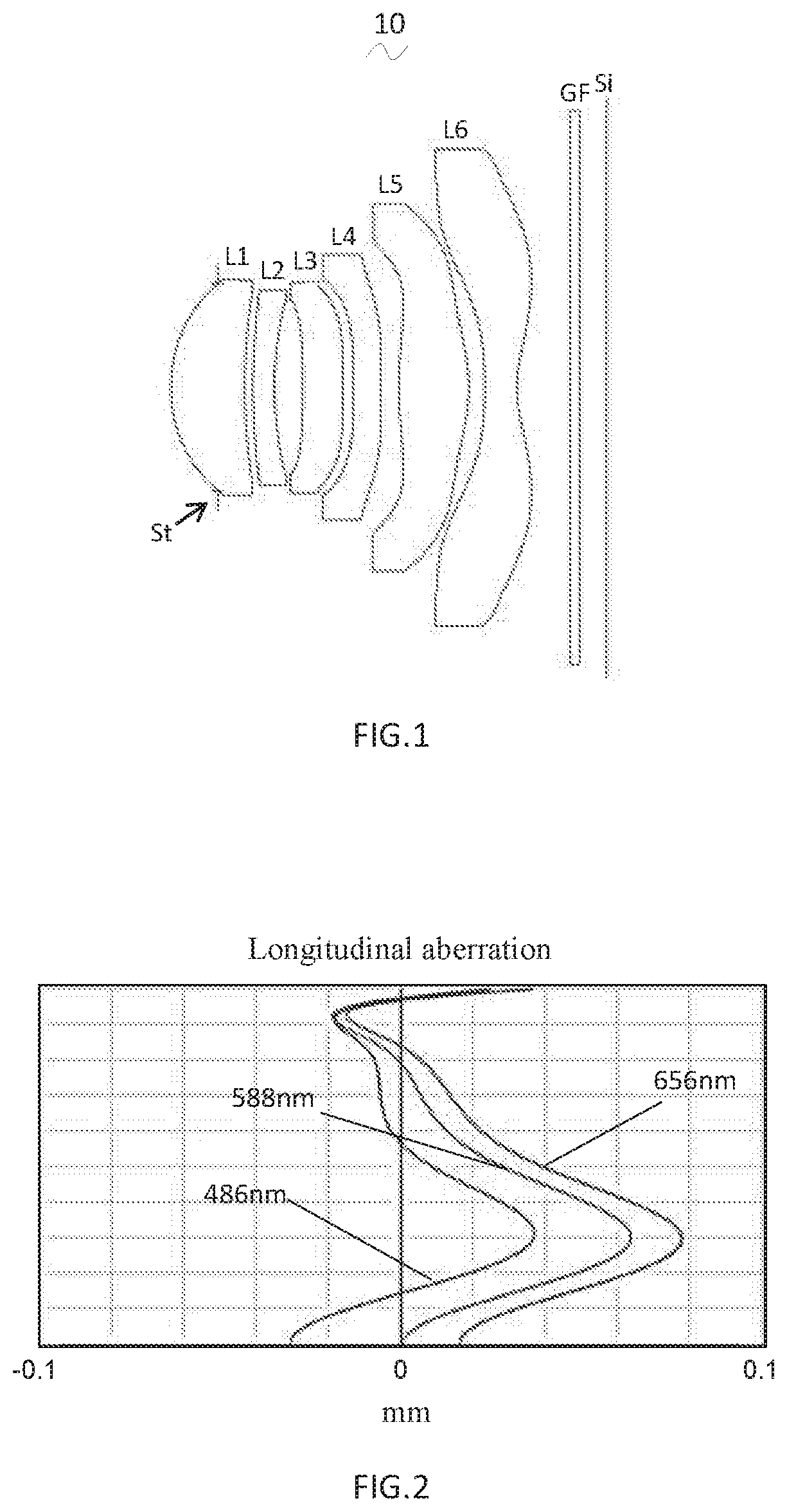
[0005] FIG. 1 is a schematic structural diagram of an imaging optical lens according to a first embodiment of the present disclosure;
[0006] FIG. 2 is a schematic diagram of a longitudinal aberration of the imaging optical lens shown in FIG. 1;
[0007] FIG. 3 is a schematic diagram of a lateral color of the imaging optical lens shown in FIG. 1;
[0008] FIG. 4 is a schematic diagram of a field curvature and a distortion of the imaging optical lens shown in FIG. 1;
[0009] FIG. 5 is a schematic structural diagram of an imaging optical lens according to a second embodiment of the present disclosure;
[0010] FIG. 6 is a schematic diagram of a longitudinal aberration of the imaging optical lens shown in FIG. 5;
[0011] FIG. 7 is a schematic diagram of a lateral color of the imaging optical lens shown in FIG. 5;
[0012] FIG. 8 is a schematic diagram of a field curvature and a distortion of the imaging optical lens shown in FIG. 5;
[0013] FIG. 9 is a schematic structural diagram of an imaging optical lens according to a third embodiment of the present disclosure;
[0014] FIG. 10 is a schematic diagram of a longitudinal aberration of the imaging optical lens shown in FIG. 9;
[0015] FIG. 11 is a schematic diagram of a lateral color of the imaging optical lens shown in FIG. 9; and
[0016] FIG. 12 is a schematic diagram of a field curvature and a distortion of the imaging optical lens shown in FIG. 9.
DETAILED DESCRIPTION
[0017] To make objectives, technical solutions, and advantages of the present disclosure clearer, the following further describes embodiments of the present disclosure in detail with reference to accompanying drawings. However, those of ordinary skill in the art may understand that in the embodiments of the present disclosure, many technique details are described to make readers better understand the present disclosure. However, the technical solutions as claimed in the present disclosure may be also realized even without these technique details or various variations and modifications based on the following embodiments.
Embodiment 1
[0018] Referring to the accompanying drawings, the present disclosure provides an imaging optical lens 10. FIG. 1 shows an imaging optical lens 10 according to the first embodiment of the present disclosure. The imaging optical lens 10 includes six lenses. Specifically, the imaging optical lens 10 includes from an object side to an image side in sequence: an aperture St, a first lens L1, a second lens L2, a third lens L3, a fourth lens L4, a fifth lens L5, and a sixth lens L6. In this embodiment, optical elements such as a glass plate GF may be disposed between the sixth lens L6 and an image surface Si. The glass plate GF may be a glass cover plate, or a filter having functions such as IR cut-off filtering. Of course, in other embodiments, the glass plate GF may also be disposed at other positions.
[0019] In this embodiment, the first lens has a positive refractive power, and has an object-side surface which is a convex surface projecting outwardly, and an image-side surface which is a concave surface. The second lens L2 has a negative refractive power, and has an object-side surface which is a convex surface, and an image-side surface which is a concave surface. The third lens L3 has a negative refractive power, and has an object-side surface which is a concave surface, and an image-side surface which is a convex surface. The fourth lens L4 has a negative refractive power, and has an object-side surface which is a convex surface, and an image-side surface which is a concave surface. The fifth lens L5 has a positive refractive power. In this embodiment, both an object-side surface and an image-side surface of the fifth lens L5 are convex surfaces. The sixth lens L6 has a negative refractive power. In this embodiment, both an object-side surface and an image-side surface of the sixth lens L6 are concave surfaces.
[0020] To better correct aberrations, preferably, surfaces of the six lenses are designed in aspheric shapes.
[0021] It is defined herein that a focal length of the imaging optical lens is f, a focal length of the third lens is f3, an Abbe number of the first lens is v1, and an Abbe number of the second lens is v2. f, f3, v1 and v2 satisfy the following relational expressions:
-500.ltoreq.f3/f.ltoreq.-50 (1)
2.7.ltoreq.v1/v2.ltoreq.5.0 (2)
[0022] A range of a ratio between the focal length of the third lens L3 and the focal length of the entire imaging optical lens 10 is specified by the relational expression (1) in this embodiment. It should be noted that as lenses are developing toward ultra-thinness, optical parameters within the range of the relational expression (1) can help correct aberrations of the imaging optical lens 10.
[0023] A range of a ratio between the Abbe number of the first lens L1 and that of the second lens L2 is specified in the relational expression (2) in this embodiment. In this way, chromatic aberrations of an optical system represented by the imaging optical lens 10 can be more effectively corrected.
[0024] With lens configuration above, this embodiment adopts the lenses (L1, L2, L3, L4, L5, and L6) which have different refractive power, and the first lens L1 and the second lens L2 of which the Abbe numbers have a specific relationship. Thus, the focal power of the lenses of the imaging optical lens 10 is properly set, and the Abbe number of the first lens L1 and the second lens L2 is reasonably distributed, so that the imaging optical lens 10 provides excellent image quality while achieving a large aperture, high light flux, and a wide angle.
[0025] Specifically, in this embodiment of the present disclosure, the first lens L1 has a positive refractive power, a thickness on-axis of the first lens L1 is d1, a focal length of the entire imaging optical lens is f, and d1 and f may be designed to satisfy the following relational expression:
0.20.ltoreq.d1/f.ltoreq.0.50 (3)
[0026] A ratio between the thickness on-axis d1 of the first lens L1 and a focal length f of the entire imaging optical lens is specified in relational expression (3) in this embodiment. Such a design facilitates a development of the imaging optical lens 10 toward a wide angle.
[0027] Further, in this embodiment of the present disclosure, the third lens L3 has a negative refractive power, a thickness on-axis of the third lens L3 is d5, a focal length of the entire imaging optical lens 10 is f, and d5 and f may be designed to satisfy the following relational expression:
0.11.ltoreq.d5/f.ltoreq.0.2 (4)
[0028] A ratio between the thickness on-axis d5 of the third lens L3 and the focal length f of the entire imaging optical lens is specified in relational expression (4) in this embodiment. Such a configuration facilitates the development of the imaging optical lens 10 toward a wide angle.
[0029] In addition, in this embodiment, a curvature radius of the object-side surface of the first lens L1 is R1, and a curvature radius of the image-side surface of the first lens L1 is R2, and R1 and R2 may be designed to satisfy the following relational expression:
-1.90.ltoreq.(R1+R2)/(R1-R2).ltoreq.-1.7 (5)
[0030] A shape of the first lens L1 is specified in the relational expression (5) in this embodiment. As lenses are developing toward a wide angle and a large aperture, R1 and R5 within a range of the relational expression (5) can help correct higher-order aberrations such as spherical aberrations of the imaging optical lens 10.
[0031] It should be noted that as the first lens L1, the second lens L2, the third lens L3, the fourth lens L4, the fifth lens L5, and the sixth lens L6 that constitute the imaging optical lens 10 in this embodiment have a structure and a parameter relationship above, the imaging optical lens 10 can reasonably distribute the focal power, a surface shape, a material, the thickness on-axis, and the like of each lens, and thus correct aberrations. Therefore, for the optical imaging system represented by the imaging optical lens 10 of the present disclosure, Fno.ltoreq.1.75, thereby providing excellent image quality while achieving a large aperture, high light flux, and a wide angle.
[0032] FIG. 1 is a schematic structural diagram of the imaging optical lens 10 in the first embodiment. Design data of the imaging optical lens 10 in the first embodiment of the present disclosure is shown below.
[0033] Table 1 illustrates the curvature radii r of the object-side surface and the image-side surface of the first lens L1 to the sixth lens L6 that constitute the imaging optical lens 10 in this embodiment (the first embodiment), the thickness on-axis d of each lens or a distance on-axis d between lenses, and a refractive index nd and an Abbe number vd of each lens. It should be noted that, in this embodiment, the curvature radius and the thickness on-axis are measured in millimeters (mm).
TABLE-US-00001 TABLE 1 r d nd .nu.d St .infin. d0 = -0.497 R1 1.505 d1 = 0.785 nd1 1.5286 .nu.1 76.98 R2 4.949 d2 = 0.090 R3 4.373 d3 = 0.229 nd2 1.6614 .nu.2 20.41 R4 3.205 d4 = 0.304 R5 -52.054 d5 = 0.427 nd3 1.5445 .nu.3 55.99 R6 -73.144 d6 = 0.112 R7 241.292 d7 = 0.293 nd4 1.6150 .nu.4 25.92 R8 9.737 d8 = 0.191 R9 4.957 d9 = 0.748 nd5 1.5445 .nu.5 55.99 R10 -1.487 d10 = 0.168 R11 -5.498 d11 = 0.345 nd6 1.5352 .nu.6 56.09 R12 1.250 d12 = 0.562 R13 .infin. d13 = 0.110 ndg 1.5168 .nu..sub.g 64.17 R14 .infin. d14 = 0.284
[0034] Meanings of the symbols in the table above are as follows.
[0035] r: the curvature radius of an optical surface;
[0036] St: the aperture;
[0037] R1: the object-side surface of the first lens L1;
[0038] R2: the image-side surface of the first lens L1;
[0039] R3: the object-side surface of the second lens L2;
[0040] R4: the image-side surface of the second lens L2;
[0041] R5: the object-side surface of the third lens L3;
[0042] R6: the image-side surface of the third lens L3;
[0043] R7: the object-side surface of the fourth lens L4;
[0044] R8: the image-side surface of the fourth lens L4;
[0045] R9: the object-side surface of the fifth lens L5;
[0046] R10: the image-side surface of the fifth lens L5;
[0047] R11: the object-side surface of the sixth lens L6;
[0048] R12: the image-side surface of the sixth lens L6;
[0049] R13: the object-side surface of the glass plate GF;
[0050] R14: the image-side surface of the glass plate GF;
[0051] d: the thickness on-axis of the lenses or the distance on-axis between neighboring lenses;
[0052] d0: the distance on-axis from the aperture St to the object-side surface of the first lens L1;
[0053] d1: the thickness on-axis of the first lens L1;
[0054] d2: the distance on-axis from the image-side surface of the first lens L1 to the object-side surface of the second lens L2;
[0055] d3: the thickness on-axis of the second lens L2;
[0056] d4: the distance on-axis from the image-side surface of the second lens L2 to the object-side surface of the third lens L3;
[0057] d5: the thickness on-axis of the third lens L3;
[0058] d6: the distance on-axis from the image-side surface of the third lens L3 to the object-side surface of the fourth lens L4;
[0059] d7: the thickness on-axis of the fourth lens L4;
[0060] d8: the distance on-axis from the image-side surface of the fourth lens L4 to the object-side surface of the fifth lens L5;
[0061] d9: the thickness on-axis of the fifth lens L5;
[0062] d10: the distance on-axis from the image-side surface of the fifth lens L5 to the object-side surface of the sixth lens L6;
[0063] d11: the thickness on-axis of the sixth lens L6;
[0064] d12: the distance on-axis from the image-side surface of the sixth lens L6 to the object-side surface of the optical filter GF;
[0065] d13: the thickness on-axis of the glass plate GF;
[0066] d14: the distance on-axis from the image-side surface of the glass plate GF to the image surface Si;
[0067] nd: the refractive index of the d line;
[0068] nd1: the refractive index of the first lens L1;
[0069] nd2: the refractive index of the second lens L2;
[0070] nd3: the refractive index of the third lens L3;
[0071] nd4: the refractive index of the fourth lens L4;
[0072] nd5: the refractive index of the fifth lens L5;
[0073] nd6: the refractive index of the sixth lens L6;
[0074] ndg: the refractive index of the glass plate GF;
[0075] vd: the Abbe number;
[0076] v1: the Abbe number of the first lens L1;
[0077] v2: the Abbe number of the second lens L2;
[0078] v3: the Abbe number of the third lens L3;
[0079] v4: the Abbe number of the fourth lens L4;
[0080] v5: the Abbe number of the fifth lens L5;
[0081] v6: the Abbe number of the sixth lens L6; and
[0082] vg: the Abbe number of the glass plate GF.
[0083] Table 2 illustrates aspheric data of lenses of the imaging optical lens 10 in the first embodiment of the present disclosure.
TABLE-US-00002 TABLE 2 Conic coefficient Aspheric coefficient k A4 A6 A8 A10 A12 A14 A16 R1 -2.46E-01 -2.72E-03 9.44E-02 -2.65E-01 4.62E-01 -4.49E-01 2.31E-01 -4.84E-02 R2 1.50E+01 -4.17E-02 -9.72E-02 3.84E-01 -6.71E-01 6.28E-01 -3.03E-01 5.43E-02 R3 9.27E+00 -1.32E-01 5.96E-02 9.77E-02 -2.41E-01 2.73E-01 -1.63E-01 3.86E-02 R4 9.10E+00 -1.31E-01 1.47E-01 -4.40E-01 1.18E+00 -1.85E+00 1.48E+00 -4.80E-01 R5 1.77E+02 -1.35E-01 1.56E-01 -7.67E-01 1.65E+00 -2.05E+00 1.30E+00 -3.10E-01 R6 -5.00E+02 -1.63E-01 -1.28E-01 9.53E-01 -2.79E+00 3.82E+00 -2.55E+00 6.73E-01 R7 -4.98E+02 -2.39E-01 -4.92E-03 7.03E-01 -1.79E+00 2.02E+00 -1.10E+00 2.26E-01 R8 2.22E+00 -2.55E-01 1.63E-01 -8.35E-02 2.99E-02 1.25E-02 -1.37E-02 2.87E-03 R9 -3.26E+01 1.55E-02 -8.62E-02 5.38E-02 -3.28E-02 1.16E-02 -1.89E-03 1.35E-04 R10 -9.28E+00 9.80E-02 -4.16E-02 -6.15E-03 6.34E-03 -1.41E-03 1.15E-04 -1.97E-06 R11 -8.48E-01 -1.51E-01 8.76E-02 -2.60E-02 6.50E-03 -1.39E-03 1.87E-04 -1.10E-05 R12 -9.80E+00 -1.23E-01 6.77E-02 -2.80E-02 7.29E-03 -1.14E-03 1.02E-04 -4.04E-06
[0084] In table 2, K is a conic coefficient, and A4, A6, A8, A10, A12, A14, and A16 are aspheric coefficients.
[0085] It should be noted that, preferably, aspheric surfaces shown in the following relational expression (6) are used as aspheric surfaces of the lenses in this embodiment. However, aspheric surfaces shown in the following relational expression (6) is only an example, and in practice, the present disclosure is not limited to the aspheric surfaces shown in the relational expression (6).
Y=(x.sup.2/R)/{1+[1-(1+k)(x.sup.2/R.sup.2)].sup.1/2}.+-.A.sub.4x.sup.4+A- .sub.6x.sup.6+A.sub.8x.sup.8+A.sub.10x.sup.10+A.sub.12x.sup.12+A.sub.14x.s- up.14+A.sub.16x.sup.16 (6)
[0086] In addition, Table 7 below further shows values of f, f1, f2, f3, f4, f5, and f6 in the first embodiment, and f and f3, v1 and v2, d1 and f, d5 and f, and R1 and R2 respectively satisfy relational expressions listed in Table 7. FIG. 2 and FIG. 3 are respectively schematic diagrams of a longitudinal aberration and a lateral color obtained when light having wavelengths of 486 nm, 588 nm and 656 nm passes through the imaging optical lens 10 in the first embodiment. FIG. 4 illustrates a schematic diagram of a field curvature and a distortion obtained when light having a wavelength of 588 nm passes through the imaging optical lens 10 in the first embodiment. In FIG. 4, S is a field curvature in a sagittal direction, and T is a field curvature in a meridian direction.
[0087] In this embodiment, a full angle of view of the imaging optical lens 10 is 2.omega., and an F value is Fno, where 2.omega.=73.06.degree. and Fno=1.732. In this way, the imaging optical lens 10 has a wide angle and high light flux, and excellent optical properties.
Embodiment 2
[0088] FIG. 5 is a schematic structural diagram of an imaging optical lens 20 in the second embodiment. The second embodiment is substantially the same as the first embodiment, and symbols in the second embodiment have the same meanings as those in the first embodiment. Only differences between the second embodiment and the first embodiment are listed below.
[0089] Table 3 illustrates curvature radii r of the object-side surface and the image-side surface of the first lens L1 to the sixth lens L6 that constitute the imaging optical lens 20 in the second embodiment, a thickness on-axis d of each lens or a distance on-axis d between lenses, and a refractive index nd and an Abbe number vd of each lens. Table 4 illustrates aspheric data of the lenses of the imaging optical lens 20 in the second embodiment.
[0090] It should be noted that, in this embodiment, the curvature radius and the thickness on-axis are measured in millimeters (mm).
TABLE-US-00003 TABLE 3 r d nd .nu.d St .infin. d0 = -0.503 R1 1.503 d1 = 0.792 nd1 1.5285 .nu.1 95.27 R2 4.942 d2 = 0.093 R3 4.367 d3 = 0.230 nd2 1.6614 .nu.2 20.41 R4 3.204 d4 = 0.308 R5 -53.442 d5 = 0.433 nd3 1.5445 .nu.3 55.99 R6 -56.772 d6 = 0.118 R7 133.154 d7 = 0.266 nd4 1.6150 .nu.4 25.92 R8 8.996 d8 = 0.191 R9 4.988 d9 = 0.748 nd5 1.5445 .nu.5 55.99 R10 -1.494 d10 = 0.165 R11 -5.488 d11 = 0.336 nd6 1.5352 .nu.6 56.09 R12 1.255 d12 = 0.567 R13 .infin. d13 = 0.110 ndg 1.5168 .nu..sub.g 64.17 R14 .infin. d14 = 0.284
TABLE-US-00004 TABLE 4 Conic coefficient Aspheric coefficient k A4 A6 A8 A10 A12 A14 A16 R1 -2.50E-01 -3.00E-03 9.42E-02 -2.65E-01 4.62E-01 -4.49E-01 2.31E-01 -4.84E-02 R2 1.51E+01 -4.15E-02 -9.71E-02 3.84E-01 -6.72E-01 6.28E-01 -3.03E-01 5.45E-02 R3 9.29E+00 -1.32E-01 5.96E-02 9.78E-02 -2.41E-01 2.74E-01 -1.63E-01 3.86E-02 R4 9.11E+00 -1.32E-01 1.47E-01 -4.40E-01 1.18E+00 -1.85E+00 1.48E+00 -4.81E-01 R5 3.73E+02 -1.36E-01 1.56E-01 -7.67E-01 1.65E+00 -2.05E+00 1.30E+00 -3.11E-01 R6 -5.00E+02 -1.63E-01 -1.28E-01 9.53E-01 -2.79E+00 3.82E+00 -2.55E+00 6.73E-01 R7 -5.00E+02 -2.41E-01 -5.93E-03 7.02E-01 -1.79E+00 2.02E+00 -1.10E+00 2.26E-01 R8 7.52E+00 -2.54E-01 1.63E-01 -8.36E-02 2.98E-02 1.24E-02 -1.37E-02 2.88E-03 R9 -2.76E+01 1.76E-02 -8.58E-02 5.39E-02 -3.28E-02 1.17E-02 -1.88E-03 1.36E-04 R10 -9.44E+00 9.82E-02 -4.16E-02 -6.17E-03 6.33E-03 -1.41E-03 1.15E-04 -1.77E-06 R11 -8.49E-01 -1.51E-01 8.76E-02 -2.60E-02 6.50E-03 -1.39E-03 1.87E-04 -1.10E-05 R12 -1.02E+01 -1.23E-01 6.77E-02 -2.80E-02 7.29E-03 -1.14E-03 1.02E-04 -4.04E-06
[0091] Table 7 below exemplarily shows values of f, f1, f2, f3, f4, f5, and f6 in the second embodiment, and f and f3, v1 and v2, d1 and f, d5 and f, and R1 and R2 respectively satisfy the relational expressions listed in Table 7.
[0092] FIG. 6 and FIG. 7 are respectively schematic diagrams of a longitudinal aberration and a lateral color obtained when light having wavelengths of 486 nm, 588 nm and 656 nm passes through the imaging optical lens 20 in the second embodiment. FIG. 8 is a schematic diagram of a field curvature and a distortion obtained when light having a wavelength of 588 nm passes through the imaging optical lens 20 in the second embodiment.
[0093] In the imaging optical lens 20 of this embodiment, 2.omega.=72.77.degree., and Fno=1.732. In this way, the imaging optical lens 20 has a wide angle, high light flux, and excellent optical properties.
Embodiment 3
[0094] FIG. 9 is a schematic structural diagram of an imaging optical lens 30 in the third embodiment. The third embodiment is substantially the same as the first embodiment, and symbols in the third embodiment have the same meanings as those in the first embodiment. Only differences between the third embodiment and the first embodiment are listed below.
[0095] Table 5 illustrates curvature radii r of the object-side surface and the image-side surface of the first lens L1 to the sixth lens L6 that constitute the imaging optical lens 30 in the third embodiment, a thickness on-axis d of each lens or a distance on-axis d between lenses, and a refractive index nd and an Abbe number vd of each lens. Table 6 illustrates aspheric data of the lenses of an imaging optical lens 30 in the third embodiment.
[0096] It should be noted that, in this embodiment, the curvature radius and the thickness on-axis are measured in millimeters (mm).
TABLE-US-00005 TABLE 5 r d nd .nu.d St .infin. d0 = -0.482 R1 1.508 d1 = 0.782 nd1 1.5277 .nu.1 63.80 R2 4.945 d2 = 0.086 R3 4.375 d3 = 0.227 nd2 1.6614 .nu.2 20.41 R4 3.204 d4 = 0.300 R5 -56.031 d5 = 0.423 nd3 1.5445 .nu.3 55.99 R6 -66.544 d6 = 0.106 R7 162.282 d7 = 0.311 nd4 1.6150 .nu.4 25.92 R8 9.932 d8 = 0.193 R9 4.895 d9 = 0.750 nd5 1.5445 .nu.5 55.99 R10 -1.487 d10 = 0.168 R11 -5.555 d11 = 0.349 nd6 1.5352 .nu.6 56.09 R12 1.251 d12 = 0.554 R13 .infin. d13 = 0.110 ndg 1.5168 .nu..sub.g 64.17 R14 .infin. d14 = 0.284
TABLE-US-00006 TABLE 6 Conic coefficient Aspheric coefficient k A4 A6 A8 A10 A12 A14 A16 R1 -2.43E-01 -2.43E-03 9.45E-02 -2.65E-01 4.62E-01 -4.49E-01 2.31E-01 -4.84E-02 R2 1.50E+01 -4.20E-02 -9.71E-02 3.84E-01 -6.72E-01 6.27E-01 -3.03E-01 5.44E-02 R3 9.27E+00 -1.32E-01 5.96E-02 9.76E-02 -2.41E-01 2.73E-01 -1.63E-01 3.84E-02 R4 9.12E+00 -1.31E-01 1.47E-01 -4.40E-01 1.18E+00 -1.85E+00 1.48E+00 -4.80E-01 R5 4.09E+02 -1.36E-01 1.55E-01 -7.67E-01 1.65E+00 -2.05E+00 1.30E+00 -3.09E-01 R6 -5.00E+02 -1.63E-01 -1.27E-01 9.54E-01 -2.79E+00 3.82E+00 -2.55E+00 6.72E-01 R7 5.00E+02 -2.37E-01 -3.80E-03 7.05E-01 -1.78E+00 2.02E+00 -1.10E+00 2.26E-01 R8 -5.69E+00 -2.56E-01 1.62E-01 -8.37E-02 2.98E-02 1.24E-02 -1.37E-02 2.86E-03 R9 -3.51E+01 1.38E-02 -8.70E-02 5.35E-02 -3.29E-02 1.16E-02 -1.90E-03 1.31E-04 R10 -9.23E+00 9.79E-02 -4.16E-02 -6.18E-03 6.33E-03 -1.41E-03 1.15E-04 -1.95E-06 R11 -8.73E-01 -1.51E-01 8.76E-02 -2.60E-02 6.50E-03 -1.39E-03 1.87E-04 -1.10E-05 R12 -9.70E+00 -1.23E-01 6.77E-02 -2.80E-02 7.29E-03 -1.14E-03 1.02E-04 -4.04E-06
[0097] Table 7 below exemplarily shows values of f, f1, f2, f3, f4, f5, and f6 in the third embodiment, and f and f3, v1 and v2, d1 and f, d5 and f, and R1 and R2 respectively satisfy the relational expressions listed in Table 7.
[0098] FIG. 10 and FIG. 11 are respectively schematic diagrams of a longitudinal aberration and a lateral color obtained when light having wavelengths of 486 nm, 588 nm and 656 nm passes through the imaging optical lens 30 in the third embodiment. FIG. 12 is a schematic diagram of a field curvature and a distortion obtained when light having a wavelength of 588 nm passes through the imaging optical lens 30 in the third embodiment.
[0099] In the imaging optical lens 30 of this embodiment, 2.omega.=73.62.degree., and Fno=1.75. In this way, the imaging optical lens 30 has a wide angle, high light flux, and excellent optical properties.
[0100] Table 7 below illustrates values corresponding to expressions (1), (2), (3), (4), and (5) and values of other related parameters in the first embodiment, the second embodiment, and the third embodiment based on the above expressions.
TABLE-US-00007 TABLE 7 Embodiment 1 Embodiment 2 Embodiment 3 Note f3/f -86.302 -450.572 -172.601 Relational expression (1) v1/v2 3.771 4.668 3.125 Relational expression (2) d1/f 0.204 0.204 0.205 Relational expression (3) d5/f 0.111 0.112 0.111 Relational expression (4) (R1 + R2)/(R1 - R2) -1.874 -1.875 -1.877 Relational expression (5) Fno 1.732 1.732 1.746 2w 73.059 72.773 73.619 f 3.853 3.876 3.812 f1 3.781 3.777 3.796 f2 -19.462 -19.542 -19.392 f3 -332.539 -1746.339 -657.955 f4 -16.356 -15.558 -17.060 f5 2.181 2.192 2.176 f6 -1.861 -1.867 -1.866
[0101] Those of ordinary skill in the art may understand that the foregoing embodiments are specific examples for implementing the present disclosure, and in a practical application, various variations may be made to the form and details without departing from the spirit and scope of the present disclosure.
* * * * *
D00000
D00001
D00002
D00003
D00004
D00005
D00006
XML
uspto.report is an independent third-party trademark research tool that is not affiliated, endorsed, or sponsored by the United States Patent and Trademark Office (USPTO) or any other governmental organization. The information provided by uspto.report is based on publicly available data at the time of writing and is intended for informational purposes only.
While we strive to provide accurate and up-to-date information, we do not guarantee the accuracy, completeness, reliability, or suitability of the information displayed on this site. The use of this site is at your own risk. Any reliance you place on such information is therefore strictly at your own risk.
All official trademark data, including owner information, should be verified by visiting the official USPTO website at www.uspto.gov. This site is not intended to replace professional legal advice and should not be used as a substitute for consulting with a legal professional who is knowledgeable about trademark law.