Counter Flow Heat Exchanger
Palmer; Nigel ; et al.
U.S. patent application number 16/054253 was filed with the patent office on 2020-02-06 for counter flow heat exchanger. The applicant listed for this patent is Hamilton Sundstrand Corporation. Invention is credited to Ahmet Becene, Feng Feng, Luke Martin, Patrick McCord, Nigel Palmer, Gabriel Ruiz, James Streeter, Joseph Turney.
| Application Number | 20200041212 16/054253 |
| Document ID | / |
| Family ID | 67438881 |
| Filed Date | 2020-02-06 |


| United States Patent Application | 20200041212 |
| Kind Code | A1 |
| Palmer; Nigel ; et al. | February 6, 2020 |
COUNTER FLOW HEAT EXCHANGER
Abstract
A counter-flow heat exchanger including: a primary flow passageway comprising a primary flow inlet, a primary flow outlet, and a plurality of primary flow subset passageways therebetween; a secondary flow passageway comprising a secondary flow inlet, a secondary flow outlet, and a plurality of secondary flow subset passageways therebetween; and a heat exchanger core comprising portions of the plurality of primary flow subset passageways and the plurality of secondary flow subset passageways, the secondary flow passageway being in thermal communication with the primary flow passageway in the heat exchanger core, wherein the primary flow subset passageways in the heat exchanger core and the secondary flow subset passageways in the heat exchanger core are oriented such that primary fluid flow through the primary flow subset passageways flows opposite secondary fluid flow through the secondary flow subset passageways.
| Inventors: | Palmer; Nigel; (West Granby, CT) ; Becene; Ahmet; (West Simsbury, CT) ; McCord; Patrick; (Norwich, CT) ; Streeter; James; (Torrington, CT) ; Feng; Feng; (South Windsor, CT) ; Martin; Luke; (Enfield, CT) ; Ruiz; Gabriel; (Granby, CT) ; Turney; Joseph; (Amston, CT) | ||||||||||
| Applicant: |
|
||||||||||
|---|---|---|---|---|---|---|---|---|---|---|---|
| Family ID: | 67438881 | ||||||||||
| Appl. No.: | 16/054253 | ||||||||||
| Filed: | August 3, 2018 |
| Current U.S. Class: | 1/1 |
| Current CPC Class: | F28D 7/1607 20130101; F28F 2255/18 20130101; F28F 1/025 20130101; F28F 2210/02 20130101; F28D 7/0008 20130101; F28F 9/0256 20130101; F28D 7/0033 20130101; F28D 2021/0021 20130101; F28D 2021/0026 20130101; F28D 9/0081 20130101; F28D 7/1646 20130101; F28F 9/0275 20130101; F28F 7/02 20130101 |
| International Class: | F28D 7/16 20060101 F28D007/16; F28D 7/00 20060101 F28D007/00; F28D 9/00 20060101 F28D009/00; F28F 9/02 20060101 F28F009/02; F28F 1/02 20060101 F28F001/02 |
Claims
1. A counter-flow heat exchanger, comprising: a primary flow passageway comprising a primary flow inlet, a primary flow outlet, and a plurality of primary flow subset passageways therebetween; a secondary flow passageway comprising a secondary flow inlet, a secondary flow outlet, and a plurality of secondary flow subset passageways therebetween; and a heat exchanger core comprising portions of the plurality of primary flow subset passageways and the plurality of secondary flow subset passageways, the secondary flow passageway being in thermal communication with the primary flow passageway in the heat exchanger core, wherein the primary flow subset passageways in the heat exchanger core and the secondary flow subset passageways in the heat exchanger core are oriented such that primary fluid flow through the primary flow subset passageways flows opposite secondary fluid flow through the secondary flow subset passageways.
2. The counter-flow heat exchanger of claim 1, wherein the primary flow passageway further comprises a primary flow inlet fractal header fluidly connecting the primary flow inlet to each of the plurality of primary flow subset passageways, the primary flow inlet fractal header being configured to fractally branch the fluid flow from a single passageway at the primary flow inlet to the plurality of primary flow subset passageways.
3. The counter-flow heat exchanger of claim 1, wherein the secondary flow passageway further comprises a secondary flow inlet fractal header fluidly connecting the secondary flow inlet to each of the plurality of secondary flow subset passageways, the secondary flow inlet fractal header being configured to fractally branch the fluid flow from a single passageway at the secondary flow inlet to the plurality of secondary flow subset passageways.
4. The counter-flow heat exchanger of claim 2, wherein the secondary flow passageway further comprises a secondary flow inlet fractal header fluidly connecting the secondary flow inlet to each of the plurality of secondary flow subset passageways, the secondary flow inlet fractal header being configured to fractally branch the fluid flow from a single passageway at the secondary flow inlet to the plurality of secondary flow subset passageways.
5. The counter-flow heat exchanger of claim 1, wherein the primary flow passageway further comprises a primary flow outlet fractal header fluidly connecting the primary flow outlet to each of the plurality of primary flow subset passageways, the primary flow outlet fractal header being configured to fractally unify the primary flow subset passageways to a single passageway at the primary flow outlet.
6. The counter-flow heat exchanger of claim 1, wherein the secondary flow passageway further comprises a secondary flow outlet fractal header fluidly connecting the secondary flow outlet to each of the plurality of secondary flow subset passageways, the secondary flow outlet fractal header being configured to fractally unify the secondary flow subset passageways to a single passageway at the secondary flow outlet.
7. The counter-flow heat exchanger of claim 2, wherein the primary flow passageway further comprises a primary flow outlet fractal header fluidly connecting the primary flow outlet to each of the plurality of primary flow subset passageways, the primary flow outlet fractal header being configured to fractally unify the primary flow subset passageways to a single passageway at the primary flow outlet.
8. The counter-flow heat exchanger of claim 3, wherein the secondary flow passageway further comprises a secondary flow outlet fractal header fluidly connecting the secondary flow outlet to each of the plurality of secondary flow subset passageways, the secondary flow outlet fractal header being configured to fractally unify the secondary flow subset passageways to a single passageway at the secondary flow outlet.
9. The counter-flow heat exchanger of claim 4, wherein the primary flow passageway further comprises a primary flow outlet fractal header fluidly connecting the primary flow outlet to each of the plurality of primary flow subset passageways, the primary flow outlet fractal header being configured to fractally unify the primary flow subset passageways to a single passageway at the primary flow outlet.
10. The counter-flow heat exchanger of claim 4, wherein the secondary flow passageway further comprises a secondary flow outlet fractal header fluidly connecting the secondary flow outlet to each of the plurality of secondary flow subset passageways, the secondary flow outlet fractal header being configured to fractally unify the secondary flow subset passageways to a single passageway at the secondary flow outlet.
11. The counter-flow heat exchanger of claim 10, wherein the primary flow passageway further comprises a primary flow outlet fractal header fluidly connecting the primary flow outlet to each of the plurality of primary flow subset passageways, the primary flow outlet fractal header being configured to fractally unify the primary flow subset passageways to a single passageway at the primary flow outlet.
12. The counter-flow heat exchanger of claim 1, wherein the counter-flow heat exchanger is built in a single piece using additive manufacturing.
13. The counter-flow heat exchanger of claim 1, wherein multiple linearly extending cylinders form each individual primary flow subset passageway and each individual secondary flow subset passageway within the heat exchanger core.
14. The counter-flow heat exchanger of claim 1, wherein multiple curvilinear extending cylinders form each individual primary flow subset passageway and each individual secondary flow subset passageway within the heat exchanger core.
15. The counter-flow heat exchanger of claim 1, wherein the heat exchanger core is composed of parallel alternating layers of the primary flow subset passageways and the secondary flow subset passageways.
16. The counter-flow heat exchanger of claim 1, wherein at least one of the primary flow subset passageways and the secondary flow subset passageways are circular in shape.
17. The counter-flow heat exchanger of claim 1, wherein the primary flow subset passageways are physically connected to the secondary flow subset passageways within the heat exchanger core.
18. A method of manufacturing a counter-flow heat exchanger, the method comprising: forming a counter-flow heat exchanger using additive manufacturing, the counter flow heat exchanger comprising: a primary flow passageway comprising a primary flow inlet, a primary flow outlet, and a plurality of primary flow subset passageways therebetween; a secondary flow passageway comprising a secondary flow inlet, a secondary flow outlet, and a plurality of secondary flow subset passageways therebetween; and a heat exchanger core comprising portions of the plurality of primary flow subset passageways and the plurality of secondary flow subset passageways, the secondary flow passageway being in thermal communication with the primary flow passageway in the heat exchanger core, wherein the primary flow subset passageways in the heat exchanger core and the secondary flow subset passageways in the heat exchanger core are oriented such that primary fluid flow through the primary flow subset passageways flows opposite secondary fluid flow through the secondary flow subset passageways.
19. The method of claim 18, wherein the additive manufacturing is via direct metal laser sintering.
Description
BACKGROUND
[0001] The subject matter disclosed herein generally relates to the field of heat exchangers, and more particularly to method and apparatus for heat exchangers of aircraft.
[0002] Heat exchangers are conventionally utilized in aircraft to removed heat from fluid flows. Heat exchangers utilized aircraft must be designed to fit in limited volumes, which may reduce overall heat exchange efficiency of the heat exchangers and/or impede the flow of fluid through the heat exchanger.
BRIEF SUMMARY
[0003] According to one embodiment, a counter-flow heat exchanger is provided. The counter-flow heat exchanger including: a primary flow passageway comprising a primary flow inlet, a primary flow outlet, and a plurality of primary flow subset passageways therebetween; a secondary flow passageway comprising a secondary flow inlet, a secondary flow outlet, and a plurality of secondary flow subset passageways therebetween; and a heat exchanger core comprising portions of the plurality of primary flow subset passageways and the plurality of secondary flow subset passageways, the secondary flow passageway being in thermal communication with the primary flow passageway in the heat exchanger core, wherein the primary flow subset passageways in the heat exchanger core and the secondary flow subset passageways in the heat exchanger core are oriented such that primary fluid flow through the primary flow subset passageways flows opposite secondary fluid flow through the secondary flow subset passageways.
[0004] In addition to one or more of the features described above, or as an alternative, further embodiments may include that the primary flow passageway further comprises a primary flow inlet fractal header fluidly connecting the primary flow inlet to each of the plurality of primary flow subset passageways, the primary flow inlet fractal header being configured to fractally branch the fluid flow from a single passageway at the primary flow inlet to the plurality of primary flow subset passageways.
[0005] In addition to one or more of the features described above, or as an alternative, further embodiments may include that the secondary flow passageway further comprises a secondary flow inlet fractal header fluidly connecting the secondary flow inlet to each of the plurality of secondary flow subset passageways, the secondary flow inlet fractal header being configured to fractally branch the fluid flow from a single passageway at the secondary flow inlet to the plurality of secondary flow subset passageways.
[0006] In addition to one or more of the features described above, or as an alternative, further embodiments may include that the secondary flow passageway further comprises a secondary flow inlet fractal header fluidly connecting the secondary flow inlet to each of the plurality of secondary flow subset passageways, the secondary flow inlet fractal header being configured to fractally branch the fluid flow from a single passageway at the secondary flow inlet to the plurality of secondary flow subset passageways.
[0007] In addition to one or more of the features described above, or as an alternative, further embodiments may include that the primary flow passageway further comprises a primary flow outlet fractal header fluidly connecting the primary flow outlet to each of the plurality of primary flow subset passageways, the primary flow outlet fractal header being configured to fractally unify the primary flow subset passageways to a single passageway at the primary flow outlet.
[0008] In addition to one or more of the features described above, or as an alternative, further embodiments may include that the secondary flow passageway further comprises a secondary flow outlet fractal header fluidly connecting the secondary flow outlet to each of the plurality of secondary flow subset passageways, the secondary flow outlet fractal header being configured to fractally unify the secondary flow subset passageways to a single passageway at the secondary flow outlet.
[0009] In addition to one or more of the features described above, or as an alternative, further embodiments may include that the primary flow passageway further comprises a primary flow outlet fractal header fluidly connecting the primary flow outlet to each of the plurality of primary flow subset passageways, the primary flow outlet fractal header being configured to fractally unify the primary flow subset passageways to a single passageway at the primary flow outlet.
[0010] In addition to one or more of the features described above, or as an alternative, further embodiments may include that the secondary flow passageway further comprises a secondary flow outlet fractal header fluidly connecting the secondary flow outlet to each of the plurality of secondary flow subset passageways, the secondary flow outlet fractal header being configured to fractally unify the secondary flow subset passageways to a single passageway at the secondary flow outlet.
[0011] In addition to one or more of the features described above, or as an alternative, further embodiments may include that the primary flow passageway further comprises a primary flow outlet fractal header fluidly connecting the primary flow outlet to each of the plurality of primary flow subset passageways, the primary flow outlet fractal header being configured to fractally unify the primary flow subset passageways to a single passageway at the primary flow outlet.
[0012] In addition to one or more of the features described above, or as an alternative, further embodiments may include that the secondary flow passageway further comprises a secondary flow outlet fractal header fluidly connecting the secondary flow outlet to each of the plurality of secondary flow subset passageways, the secondary flow outlet fractal header being configured to fractally unify the secondary flow subset passageways to a single passageway at the secondary flow outlet.
[0013] In addition to one or more of the features described above, or as an alternative, further embodiments may include that the primary flow passageway further comprises a primary flow outlet fractal header fluidly connecting the primary flow outlet to each of the plurality of primary flow subset passageways, the primary flow outlet fractal header being configured to fractally unify the primary flow subset passageways to a single passageway at the primary flow outlet.
[0014] In addition to one or more of the features described above, or as an alternative, further embodiments may include that the counter-flow heat exchanger is built in a single piece using additive manufacturing.
[0015] In addition to one or more of the features described above, or as an alternative, further embodiments may include that multiple linearly extending cylinders form each individual primary flow subset passageway and each individual secondary flow subset passageway within the heat exchanger core.
[0016] In addition to one or more of the features described above, or as an alternative, further embodiments may include that multiple curvilinear extending cylinders form each individual primary flow subset passageway and each individual secondary flow subset passageway within the heat exchanger core.
[0017] In addition to one or more of the features described above, or as an alternative, further embodiments may include that the heat exchanger core is composed of parallel alternating layers of the primary flow subset passageways and the secondary flow subset passageways.
[0018] In addition to one or more of the features described above, or as an alternative, further embodiments may include that at least one of the primary flow subset passageways and the secondary flow subset passageways are circular in shape.
[0019] In addition to one or more of the features described above, or as an alternative, further embodiments may include that the primary flow subset passageways are physically connected to the secondary flow subset passageways within the heat exchanger core.
[0020] According to another embodiment, a method of manufacturing a counter-flow heat exchanger is provided. The method including: forming a counter-flow heat exchanger using additive manufacturing, the counter flow heat exchanger comprising: a primary flow passageway comprising a primary flow inlet, a primary flow outlet, and a plurality of primary flow subset passageways therebetween; a secondary flow passageway comprising a secondary flow inlet, a secondary flow outlet, and a plurality of secondary flow subset passageways therebetween; and a heat exchanger core comprising portions of the plurality of primary flow subset passageways and the plurality of secondary flow subset passageways, the secondary flow passageway being in thermal communication with the primary flow passageway in the heat exchanger core, wherein the primary flow subset passageways in the heat exchanger core and the secondary flow subset passageways in the heat exchanger core are oriented such that primary fluid flow through the primary flow subset passageways flows opposite secondary fluid flow through the secondary flow subset passageways.
[0021] In addition to one or more of the features described above, or as an alternative, further embodiments may include that the additive manufacturing is via direct metal laser sintering.
[0022] Technical effects of embodiments of the present disclosure include manufacturing a counter-flow heat exchanger having fractal headers using additive manufacturing.
[0023] The foregoing features and elements may be combined in various combinations without exclusivity, unless expressly indicated otherwise. These features and elements as well as the operation thereof will become more apparent in light of the following description and the accompanying drawings. It should be understood, however, that the following description and drawings are intended to be illustrative and explanatory in nature and non-limiting.
BRIEF DESCRIPTION
[0024] The following descriptions should not be considered limiting in any way. With reference to the accompanying drawings, like elements are numbered alike:
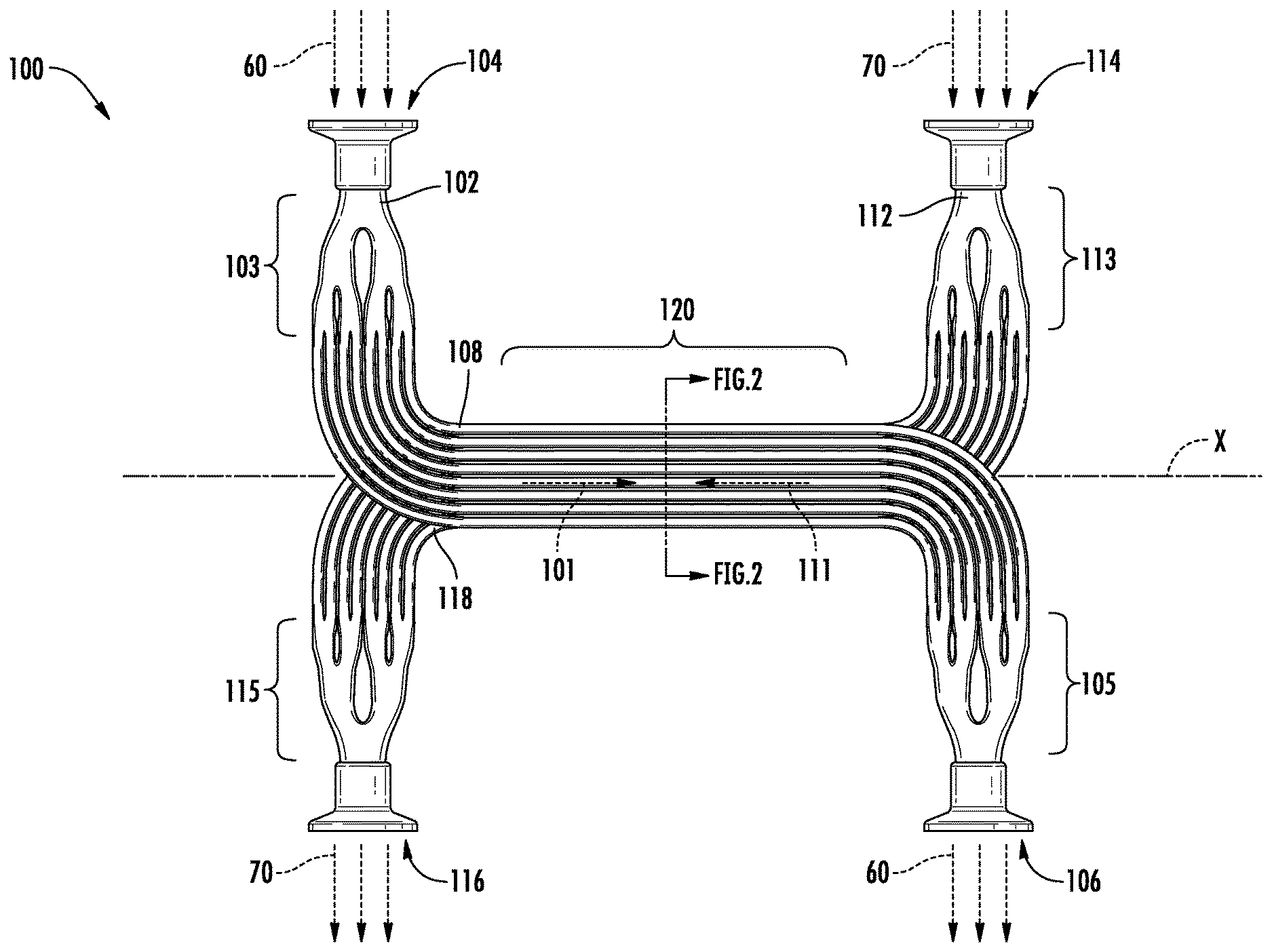
[0025] FIG. 1 is a top view of a counter-flow heat exchanger, according to an embodiment of the present disclosure; and
[0026] FIG. 2 is a cross-sectional view of a heat exchanger core of the counter-flow heat exchanger, according to an embodiment of the present disclosure.
DETAILED DESCRIPTION
[0027] A detailed description of one or more embodiments of the disclosed apparatus and method are presented herein by way of exemplification and not limitation with reference to the Figures.
[0028] FIG. 1 is a top view of a counter-flow heat exchanger 100, according to an embodiment of the present disclosure. The counter-flow heat exchanger 100 may be utilized in a variety of applications requiring thermal dynamic transfer of heat including but not limited to an aircraft, a combustion engine, a car, a space craft, a powerplant, a satellite, satellite, etc. In an embodiment, the counter-flow heat exchanger 100 may be utilized in an aircraft. In another embodiment, the counter-flow heat exchanger 100 may be utilized in an aircraft air conditioning system.
[0029] The counter-flow heat exchanger 100 includes a heat exchanger core 120 that may be oriented along a longitudinal axis X. The counter-flow heat exchanger 100 includes a primary flow passageway 102 and a secondary flow passageway 112 in thermal communication with the primary flow passageway 102. In an embodiment, the primary flow passageways 102 is configured to convey a primary fluid 60 and the secondary flow passageway 112 is configured to convey a secondary fluid 70. The primary fluid 60 may be at a temperature greater than the secondary fluid 70. The primary fluid 60 may be a liquid or a gas and the secondary fluid 70 may be a liquid or a gas. In another embodiment, the hot fluid and the cooling fluid may be airflow.
[0030] The counter-flow heat exchanger 100 includes a primary flow inlet 104, a primary flow outlet 106, and a plurality of primary flow subset passageways 108 therebetween. The flow direction of the primary fluid 60 is indicated schematically by the arrow 101. In an embodiment, the primary flow subset passageways 108 in the heat exchanger core 120 and the secondary flow subset passageways 118 in the heat exchanger core 120 are oriented such that primary fluid flow 60 through the primary flow subset passageways 108 flows opposite secondary fluid flow 70 through the secondary flow subset passageways 118.
[0031] The primary flow inlet 104 is fluidly connected to the primary flow subset passageways 108 by a primary flow inlet fractal header 103. The primary flow passageway 102 may be a single fluid passageway at the primary flow inlet 104 and then branches out into multiple primary flow subset passageways 108. The primary flow passageway 102 may branch out into two or more primary flow subset passageways 108. The primary flow passageway 102 may branch out into the multiple primary flow subset passageways 108 in progressive steps. For example, as shown in FIG. 2, the primary flow passageway 102 may branch out from a single fluid passageway at the primary flow inlet 104 into two primary flow subset passageways 108 that each branch into four primary flow subset passageways 108 (i.e., eight primary flow subset passageways 108 in total) that each branch into four primary flow subset passageways 108, thus bringing the total to thirty-two primary flow subset passageways 108. The primary flow inlet fractal header 103 is configured to fractally branch the fluid flow from the single passageway at the primary flow inlet 104 to the plurality of primary flow subset passageways 108, such that pressure drops in the primary fluid 60 flowing through the primary flow inlet fractal header 103 is optimized and/or reduced. In an embodiment, the primary flow subset passageways 108 includes thirty-two separate fluid passageways, thus the primary flow inlet fractal header 103 divides the primary fluid 60 flow from a single passageway at the primary flow inlet 104 to thirty-two separate primary flow subset passageways 108. Advantageously, the primary flow inlet fractal header 103 gently divides the primary fluid 60 flow into separate primary flow subset passageways 108 in accordance with the physical flow characteristics of the primary fluid 60 to avoid large pressure drops in the fluid. The shape and flow area of the transition regions where the primary flow subset passageways 108 branch out are designed to minimize recirculation zones and to provide a uniform amount of flow to each branch.
[0032] The primary flow outlet 106 is fluidly connected to the primary flow subset passageways 108 by a primary flow outlet fractal header 105. The primary flow passageway 102 fractally unifies (i.e., branch down) the plurality of primary flow subset passageways 108 to a single fluid passageway at the primary flow outlet 106. The primary flow passageway 102 may unify from the two or more primary flow subset passageways 108. The primary flow passageway 102 unifies from the multiple primary flow subset passageways 108 in progressive steps. For example, as shown in FIG. 2, the primary flow passageway 102 may unify from the thirty-two primary flow subset passageways 108 down to eight primary flow subset passageways 108, then from the eight primary flow subset passageways 108 down to two primary flow subset passageways 108 that unify into to a single fluid passageway at the primary flow outlet 106. The primary flow outlet fractal header 105 is configured to fractally unify the primary flow subset passageways 108 to a single passageway at the primary flow outlet 106, such that pressure drops in the primary fluid 60 flowing through the primary flow outlet fractal header 105 is optimized and/or reduced. In an embodiment, the primary flow subset passageways 108 includes thirty-two separate fluid passageways, thus the primary flow outlet fractal header 105 unifies the primary fluid 60 flow from thirty-two separate primary flow subset passageways 108 to a single passageway at the primary flow outlet 106. Advantageously, the primary flow outlet fractal header 105 gently unifies the primary fluid 60 flow from separate primary flow subset passageways 108 into a single fluid passageway in accordance with the physical flow characteristics of the primary fluid 60 to avoid large pressure drops in the fluid. The shape and flow area of the transition regions where the primary flow subset passageways 108 unify are designed to minimize recirculation zones and turbulence due to mixing of the flows from each branch.
[0033] The counter-flow heat exchanger 100 includes a secondary flow inlet 114, a secondary flow outlet 116, and a plurality of secondary flow subset passageways 118 therebetween. The flow direction of the secondary fluid 70 is indicated schematically by the arrow 111.
[0034] The secondary flow inlet 114 is fluidly connected to the secondary flow subset passageways 118 by a secondary flow inlet fractal header 113. The secondary flow passageway 112 may be a single fluid passageway at the secondary flow inlet 114 and then branches out into multiple secondary flow subset passageways 118. The secondary flow passageway 112 may branch out into two or more secondary flow subset passageways 118. The secondary flow passageway 112 may branch out into the multiple secondary flow subset passageways 118 in progressive steps. For example, as shown in FIG. 2, the secondary flow passageway 112 may branch out from a single fluid passageway at the secondary flow inlet 114 into two secondary flow subset passageways 118 that each branch into four secondary flow subset passageways 118 (i.e., eight secondary flow subset passageways 118 in total) that each branch into four secondary flow subset passageways 118, thus bringing the total to thirty-two secondary flow subset passageways 118. The secondary flow inlet fractal header 113 is configured to fractally branch the fluid flow from the single passageway at the secondary flow inlet 114 to the multiple fluid passageways in the secondary flow subset passageways 118, such that pressure drops in the secondary fluid 70 flowing through the secondary flow inlet fractal header 113 is optimized and/or reduced. In an embodiment, the secondary flow subset passageways 118 includes thirty-two separate fluid passageways, thus the secondary flow inlet fractal header 113 divides the secondary fluid 70 flow from a single passageway at the secondary flow inlet 114 to thirty-two separate secondary flow subset passageways 118. Advantageously, the secondary flow inlet fractal header 113 gently divides the secondary fluid 70 flow into separate secondary flow subset passageways 118 in accordance with the physical flow characteristics of the secondary fluid 70 to avoid large pressure drops in the fluid. The shape and flow area of the transition regions where the secondary flow subset passageways 118 branch out are designed to minimize recirculation zones and to provide a uniform amount of flow to each branch.
[0035] The secondary flow outlet 116 is fluidly connected to the secondary flow subset passageways 118 by a secondary flow outlet fractal header 115. The secondary flow passageway 112 unify (i.e., branch down) the plurality of secondary flow subset passageways 118 to a single fluid passageway at the secondary flow outlet 116. The secondary flow passageway 112 may unify from the two or more secondary flow subset passageways 118. The secondary flow passageway 112 unifies from the multiple secondary flow subset passageways 118 in progressive steps. For example, as shown in FIG. 2, the secondary flow passageway 112 may unify from the thirty-two secondary flow subset passageways 118 down to eight secondary flow subset passageways 118, then from the eight secondary flow subset passageways 118 down to two secondary flow subset passageways 118 that unify into to a single fluid passageway at the secondary flow outlet 116. The secondary flow outlet fractal header 115 is configured to fractally unify the secondary flow subset passageways 118 to a single passageway at the secondary flow outlet 116, such that pressure drops in the secondary fluid 70 flowing through the secondary flow outlet fractal header 115 is optimized and/or reduced. In an embodiment, the secondary flow subset passageways 118 includes thirty-two separate fluid passageways, thus the secondary flow outlet fractal header 115 unifies the secondary fluid 70 flow from thirty-two separate secondary flow subset passageways 118 to a single passageway at the secondary flow outlet 116. Advantageously, the secondary flow outlet fractal header 115 gently unifies the secondary fluid 70 flow from separate secondary flow subset passageways 118 into a single fluid passageway in accordance with the physical flow characteristics of the secondary fluid 70 to avoid large pressure drops in the fluid. The shape and flow area of the transition regions where the secondary flow subset passageways 118 unify are designed to minimize recirculation zones and turbulence due to mixing of the flows from each branch.
[0036] Referring now to FIGS. 1 and 2. As shown in FIG. 1, in the heat exchanger core 120, the flow direction of the secondary fluid 70 as indicated schematically by the arrow 111 is directly opposite of the flow direction of the primary fluid 60 as indicated schematically by the arrow 101. While the heat exchanger core 120 is shown as a straight section in FIG. 1, the actual heat exchanger core 120 may be bent in one or more planes to accommodate for local interferences. FIG. 2 is a cross-sectional view of the heat exchanger core 120, according to an embodiment of the present disclosure. FIG. 2 shows that the heat exchanger core 120 may be composed of parallel alternating layers of primary flow subset passageways 108 and secondary flow subset passageways 118. As shown in FIG. 2, the primary flow subset passageways 108 and secondary flow subset passageways 118 may be circular in shape. The primary flow subset passageways 108 and secondary flow subset passageways 118 may also be shaped in various other shapes including but not limited to hexagons, rectangular, non-regular, or any other geometric shapes/sections needed to maximize heat transfer and structural needs. Further, the shape of the primary flow subset passageways 108 may differ from the shapes of the secondary flow subset passageway 118. Additionally, each individual primary flow subset passageway 108 may have different shapes and each individual secondary flow subset passageway 118 may have different shapes. The shapes of each individual primary flow subset passageway 108 need not be symmetric within a flow layer or between flow layers of the heat exchanger core 120. Also, the shapes of each individual secondary flow subset passageway 118 need not be symmetric within a flow layer or between flow layers of the heat exchanger core 120. Although shown at a right angle in FIG. 1, the heat exchanger core 120 may be oriented at any angle in any plane relative to the primary flow inlet 104, the primary flow outlet 106, the secondary flow inlet 114, and/or the secondary flow outlet 116.
[0037] The counter-flow heat exchanger 100 may be formed using additive manufacturing such as, for, example, direct metal laser sintering. It is contemplated that the heat exchanger core 120 can be manufactured in a vertical direction, e.g. along vertical axis Z to build the heat exchanger core 120 along with the rest of the counter-flow heat exchanger 100 in a single piece. In an embodiment, the primary flow subset passageways 108 are physically connected to the secondary flow subset passageways 118 within the heat exchanger core 120, as shown in FIG. 2. It is also contemplated the heat exchanger core 120 can be composed of multiple linearly extending cylinders forming each individual primary flow subset passageway 108 and each individual secondary flow subset passageway 118 within the heat exchanger core 120. It is also contemplated that instead of being composed of multiple linearly extending cylinders, the heat exchanger core 120 could be built along a curvilinear path (i.e., non-linear, sinusoidal path) creating wavy or ruffled sets of passageways as opposed to straight ones for increased heat transfer or bend around obstructions.
[0038] The term fractal may be defined as a complex geometric pattern exhibiting self-similarity in that small details of its structure viewed at any scale repeat elements of the overall pattern. Advantageously, the fractals headers 103, 105, 113, 115, serve to gradually ease the transition between a single fluid passageway and multiple fluid passageways with minimal interference to the fluid flow. The term "about" is intended to include the degree of error associated with measurement of the particular quantity based upon the equipment available at the time of filing the application. For example, "about" can include a range of .+-.8% or 5%, or 2% of a given value.
[0039] The terminology used herein is for the purpose of describing particular embodiments only and is not intended to be limiting of the present disclosure. As used herein, the singular forms "a", "an" and "the" are intended to include the plural forms as well, unless the context clearly indicates otherwise. It will be further understood that the terms "comprises" and/or "comprising," when used in this specification, specify the presence of stated features, integers, steps, operations, elements, and/or components, but do not preclude the presence or addition of one or more other features, integers, steps, operations, element components, and/or groups thereof.
[0040] While the present disclosure has been described with reference to an exemplary embodiment or embodiments, it will be understood by those skilled in the art that various changes may be made and equivalents may be substituted for elements thereof without departing from the scope of the present disclosure. In addition, many modifications may be made to adapt a particular situation or material to the teachings of the present disclosure without departing from the essential scope thereof. Therefore, it is intended that the present disclosure not be limited to the particular embodiment disclosed as the best mode contemplated for carrying out this present disclosure, but that the present disclosure will include all embodiments falling within the scope of the claims.
* * * * *
D00000
D00001
D00002
XML
uspto.report is an independent third-party trademark research tool that is not affiliated, endorsed, or sponsored by the United States Patent and Trademark Office (USPTO) or any other governmental organization. The information provided by uspto.report is based on publicly available data at the time of writing and is intended for informational purposes only.
While we strive to provide accurate and up-to-date information, we do not guarantee the accuracy, completeness, reliability, or suitability of the information displayed on this site. The use of this site is at your own risk. Any reliance you place on such information is therefore strictly at your own risk.
All official trademark data, including owner information, should be verified by visiting the official USPTO website at www.uspto.gov. This site is not intended to replace professional legal advice and should not be used as a substitute for consulting with a legal professional who is knowledgeable about trademark law.