System And Method For Treating Air In An Occupiable Space
Uda; Mike
U.S. patent application number 16/530017 was filed with the patent office on 2020-02-06 for system and method for treating air in an occupiable space. The applicant listed for this patent is PetAirapy, LLC. Invention is credited to Mike Uda.
| Application Number | 20200041146 16/530017 |
| Document ID | / |
| Family ID | 69227969 |
| Filed Date | 2020-02-06 |


| United States Patent Application | 20200041146 |
| Kind Code | A1 |
| Uda; Mike | February 6, 2020 |
SYSTEM AND METHOD FOR TREATING AIR IN AN OCCUPIABLE SPACE
Abstract
The combination of: a building structure defining an occupiable space; and a system for treating air within the occupiable space. The air treating system has: a) a conduit system including at least a first conduit portion for guiding air in a predetermined path between first and second locations, the conduit portion having a plurality of outlets between the first and second locations arranged so that a portion of a volume of air traveling between the first and second locations is discharged into the occupiable space through the plurality of outlets; and b) source of UV light to which air traveling between the first and second locations is exposed before discharging through the plurality of outlets. The invention is also directed to a method of treating air, as with the air treating system.
| Inventors: | Uda; Mike; (St. Charles, IL) | ||||||||||
| Applicant: |
|
||||||||||
|---|---|---|---|---|---|---|---|---|---|---|---|
| Family ID: | 69227969 | ||||||||||
| Appl. No.: | 16/530017 | ||||||||||
| Filed: | August 2, 2019 |
Related U.S. Patent Documents
| Application Number | Filing Date | Patent Number | ||
|---|---|---|---|---|
| 62713796 | Aug 2, 2018 | |||
| Current U.S. Class: | 1/1 |
| Current CPC Class: | F24F 7/065 20130101; F24F 2003/1667 20130101; F24F 3/16 20130101; F24F 1/0014 20130101 |
| International Class: | F24F 3/16 20060101 F24F003/16; F24F 1/0014 20060101 F24F001/0014 |
Claims
1. In combination: a building structure defining an occupiable space; and a system for treating air within the occupiable space, the air treating system comprising: a) a conduit system including at least a first conduit portion for guiding air in a predetermined path between first and second locations, the conduit portion having a plurality of outlets between the first and second locations arranged so that a portion of a volume of air traveling between the first and second locations is discharged into the occupiable space through the plurality of outlets; and b) a source of UV light to which air traveling between the first and second locations is exposed before discharging through the plurality of outlets.
2. The combination according to claim 1 wherein the air treating system further comprises an air mover that causes air to travel between the first and second locations.
3. The combination according to claim 1 wherein the air treating system is a self-contained portable unit that is selectively movable to different locations within the occupiable space.
4. The combination according to claim 1 wherein the conduit system is fixedly connected to the building structure.
5. The combination according to claim 1 wherein the air treatment system has an inlet through which air is delivered to the conduit system.
6. The combination according to claim 5 wherein the building structure and air treatment system are configured so that outside air is delivered to the air treatment system inlet.
7. The combination according to claim 5 wherein the building structure and air treatment system are configured so that air within the occupiable space is delivered to the air treatment system inlet so as to be recirculated within the occupiable space.
8. The combination according to claim 1 wherein the building structure is configured to define a plurality of stalls for livestock.
9. The combination according to claim 2 wherein the air mover comprises a fan that pressurizes air to force air though the conduit system.
10. The combination according to claim 2 wherein the air mover is configured to create a low pressure region that causes air to be drawn through the conduit system.
11. The combination according to claim 1 wherein the first conduit portion extends in a substantially horizontal line.
12. The combination according to claim 1 wherein the first conduit portion extends in a substantially vertical line.
13. The combination according to claim 8 wherein the plurality of stalls comprises first and second stalls, at least one of the outlets is arranged to discharge air closer to the first stall than the second stall and at least another of the outlets is arranged to discharge air closer to the second stall than the first stall.
14. The combination according to claim 1 wherein the first conduit portion has a tubular shape with a peripheral wall and the plurality of outlets are formed through the peripheral wall.
15. A method of treating air within an occupiable space, the method comprising the steps of: effecting germicidal irradiation treatment of air within the occupiable space; and controllably delivering air after effecting treatment thereof in discrete discharge patterns at different locations within the occupiable space.
16. The method of treating air according to claim 15 wherein the step of controllably delivering air comprises controllably delivering air under pressure.
17. The method of treating air according to claim 15 wherein the step of controllably delivering air comprises delivering air through first and second discrete outlets on at least one conduit portion.
18. The method of treating air according to claim 15 further comprising the step of recirculating and effecting further germicidal irradiation treatment of the air after the air is delivered into the occupiable space.
19. The method of treating air according to claim 15 further comprising the step of moving a portable unit into the occupiable space to effect the treatment and delivery of the treated air.
20. The method of treating air according to claim 15 wherein the occupiable space is configured to confine livestock in a plurality of discrete stalls.
21. The combination according to claim 1 wherein the first conduit portion comprises a fabric material with the plurality of outlets comprising pores defined by yarns and/or fibers making up the fabric.
22. The combination according to claim 1 wherein the first conduit portion comprises a fabric material through which the plurality of outlets are formed.
Description
BACKGROUND OF THE INVENTION
Field of the Invention
[0001] This invention relates to air treatment and, more particularly, to a method and system for treating air in a space to control the spread of airborne contaminants/microorganisms.
Background Art
[0002] In recent years, there has been an increased focus on treating the air in environments occupied by pets and livestock. The primary objectives in designing air treatment systems are to afford adequate ventilation and minimize the presence of contaminants/microorganisms that might affect the health of the non-human occupants.
[0003] Providing quality air for livestock in large buildings has been particularly challenging. The most basic efforts in affording adequate ventilation involve strategic placement of openings in buildings that promote natural convection of air into and from the space.
[0004] This approach has a number of drawbacks and limitations. First of all, open buildings are only practical in environments where the climate is moderate. Further, effective air circulation within the building space requires a certain threshold of natural environmental air movement. When conditions are calm, air in the internal environment becomes stagnant and ventilation is generally inadequate. These conditions tend to promote the proliferation of undesirable contaminants/microorganisms. Still further, the intake of atmospheric air may bring in different types, and potentially significant volumes, of unwanted contaminants. The above problems are aggravated by the fact that wind direction changes, which impacts the air flow into and from a particular space.
[0005] It is known to induce air flow in buildings such as those described above. This may be effected using intake, exhaust, and overhead circulating fans. While this may reduce some of the damaging effects of stagnant air, the forced in-flow of air may bring in a significant volume of unwanted contaminants from the outside environment. Further, the outside air may be extremely hot or cold and may vary drastically in terms of its quality and temperature, which may adversely impact the comfort and health of livestock.
[0006] Some of the above systems, in their basic form, do not effect a reasonable dispersion of air in large spaces, such as barns--particularly those with individual stalls for livestock. As a result, air may circulate only in a limited volume of the space, with air being stagnant in many regions of the space, which problem is aggravated by the stall arrangement, which produces walls that block thorough air dispersion. This has led to the advent of using manifolds with multiple air directing outlets.
[0007] With this latter construction, air outlets can be strategically provided on a manifold arrangement to direct air flowing through the manifold into different regions of the space. While this, to at least some extent, addresses the problem with air stagnation, other problems described above remain. That is, the air continuously flows from the outside environment into the internal space, and commonly such environments will have entrained microorganisms which are introduced to the space. Still further, as described above, the internal temperature, humidity, etc. changes constantly as external conditions change. Thus, air conditions cannot be reasonably maintained within a desired range and health and comfort of livestock within the space may be compromised.
[0008] The above problems, while most commonly contended with in large buildings, also impact facilities with smaller spaces particularly when owners/operators choose not to use, or cannot afford to use, HVAC systems. In this category are pet boarding facilities, animal shelters, animal grooming operations, etc.
[0009] In spite of the many decades that livestock handlers and others have dealt with the above problems, there remains significant room for improvement of systems that are both affordable and effective in terms of creating a safe and comfortable environment for pets and livestock.
SUMMARY OF THE INVENTION
[0010] In one form, the invention is directed to the combination of a building structure defining an occupiable space and a system for treating air within the occupiable space. The air treating system has: a) a conduit system including at least a first conduit portion for guiding air in a predetermined path between first and second locations and having a plurality of outlets; and b) a source of UV light to which air traveling between the first and second locations is exposed before discharging through the plurality of outlets. The plurality of outlets are arranged so that a portion of a volume of air traveling between the first and second locations is discharged into the occupiable space through the plurality of outlets.
[0011] In one form, the air treating system further includes an air mover that causes air to travel between the first and second locations.
[0012] In one form, the air treating system is a self-contained portable unit that is selectively movable to different locations within the occupiable space.
[0013] In one form, the conduit system is fixedly connected to the building structure.
[0014] In one form, the air treatment system has an inlet through which air is delivered to the conduit system.
[0015] In one form, the building structure and air treatment system are configured so that outside air is delivered to the air treatment system inlet.
[0016] In one form, the building structure and air treatment system are configured so that air within the occupiable space is delivered to the air treatment system inlet so as to be recirculated within the occupiable space.
[0017] In one form, the building structure is configured to define a plurality of stalls for livestock.
[0018] In one form, the air mover has a fan that pressurizes air to force air though the conduit system.
[0019] In one form, the air mover is configured to create a low pressure region that causes air to be drawn through the conduit system.
[0020] In one form, the first conduit portion extends in a substantially horizontal line.
[0021] In one form, the first conduit portion extends in a substantially vertical line.
[0022] In one form, the plurality of stalls includes first and second stalls. At least one of the outlets is arranged to discharge air closer to the first stall than the second stall. At least another of the outlets is arranged to discharge air closer to the second stall than the first stall.
[0023] In one form, the first conduit portion has a tubular shape with a peripheral wall. The plurality of outlets are formed through the peripheral wall.
[0024] In one form, the invention is directed to a method of treating air within an occupiable space. The method includes the steps of: effecting germicidal irradiation treatment of air within the occupiable space; and controllably delivering air after effecting treatment thereof in discrete discharge patterns at different locations within the occupiable space.
[0025] In one form, the step of controllably delivering air consists of controllably delivering air under pressure.
[0026] In one form, the step of controllably delivering air includes delivering air through first and second discrete outlets on at least one conduit portion.
[0027] In one form, the method further includes the step of recirculating and effecting further germicidal irradiation treatment of the air after the air is delivered into the occupiable space.
[0028] In one form, the method further includes the step of moving a portable unit into the occupiable space to effect the treatment and delivery of the treated air.
[0029] In one form, the occupiable space is configured to confine livestock in a plurality of discrete stalls.
[0030] In one form, the first conduit portion is made up of a fabric material. The plurality of outlets are pores defined by yarns and/or fibers making up the fabric.
[0031] In one form, the first conduit portion is made up of a fabric material through which the plurality of outlets are formed.
BRIEF DESCRIPTION OF THE DRAWINGS
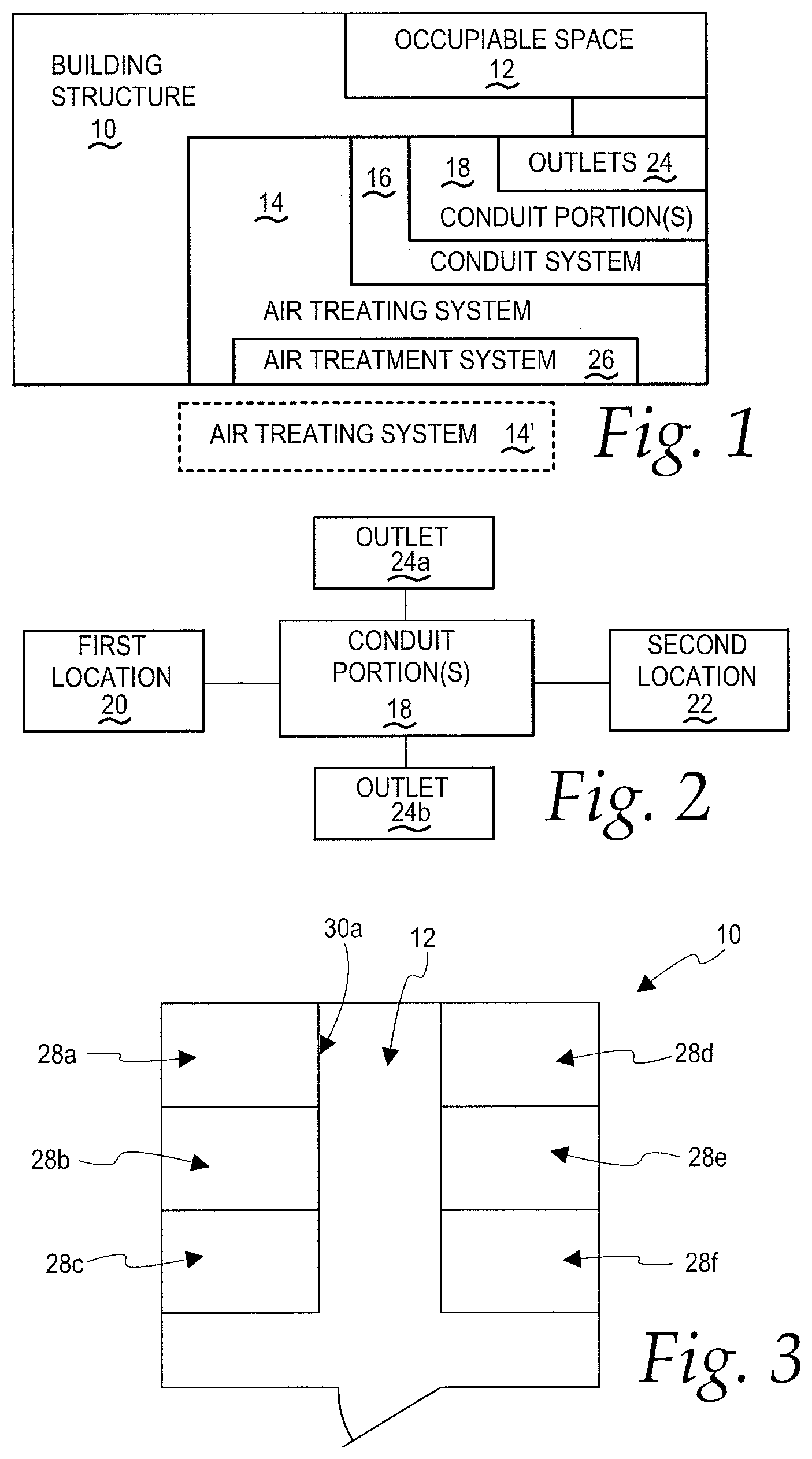
[0032] FIG. 1 is a schematic representation of the combination of a building structure defining an occupiable space and a system for treating air within the occupiable space, made according to the present invention;
[0033] FIG. 2 is a schematic representation showing further details of the conduit portion(s) shown in FIG. 1;
[0034] FIG. 3 is a plan view of one form of building structure, as shown in FIG. 1, and having multiple stalls for livestock;
[0035] FIG. 4 is one exemplary form of conduit portion as shown schematically in FIGS. 1 and 2;
[0036] FIG. 5 is a schematic representation of the conduit system as shown in FIG. 1 and showing an air mover at alternative locations in relationship thereto;
[0037] FIG. 6 is a schematic representation showing further details of the air treatment system in FIG. 1;
[0038] FIG. 7 is a schematic representation of connecting structure between one form of air treatment system and a building structure;
[0039] FIG. 8 is a schematic representation of a portable air treating system, according to the invention, and having an associated carrying handle;
[0040] FIG. 9 is a schematic representation of a portable air treating system, according to the invention, and showing a carriage for facilitating transportation thereof;
[0041] FIG. 10 is a schematic representation of a part of a building structure, as shown schematically in FIG. 1, and with the inventive conduit portion in one orientation;
[0042] FIG. 11 is a view as in FIG. 10 with the conduit portion in a different orientation;
[0043] FIG. 12 is a schematic representation of a conduit portion made from a fabric material; and
[0044] FIG. 13 is a schematic representation of a method of treating air within an occupiable space according to the invention.
DETAILED DESCRIPTION OF THE PREFERRED EMBODIMENT
[0045] In FIG. 1, the invention is shown in association with a building structure 10 that defines an occupiable space 12.
[0046] A system 14 is provided for treating air within the occupiable space 12. The air treating system 14 may be integrated into the building structure 10 or may be a separate portable unit, as shown in dotted lines at 14.degree., that may be moved into and out of the occupiable space 12.
[0047] The air treating system 14 has a conduit system 16, including at least a first conduit portion 18, for guiding air in a predetermined path between first and second locations 20, 22, as shown in FIG. 2.
[0048] The conduit portion 18 has a plurality of outlets 24 between the first and second locations 20, 22 arranged so that a portion of a volume of air traveling between the first and second locations can be strategically discharged into the occupiable space 12 through the plurality of outlets 24.
[0049] The air treating system further has an air treatment system 26 that is operable to kill or inactivate contaminants/microorganisms typically airborne within an occupiable space in which pets and livestock may be present. While not so limited, the air treatment system 26 preferably uses a source of UV light to which air traveling between the first and second locations 20, 22 is exposed before discharging through the plurality of outlets 24. It is known to use ultraviolet germicidal irradiation (UVGI) to kill or inactivate the microorganisms. Commonly, this irradiation involves use of short wavelength ultraviolet light.
[0050] The schematic depiction in FIGS. 1 and 2 is intended to show the broad concepts encompassed by the invention. While a more specific form of certain components shown in FIGS. 1 and 2 will be described hereinbelow, it should be understood that the schematic showing, while encompassing the specific forms as described hereinbelow, is also intended to encompass variations of those components and their interaction.
[0051] As one example, the building structure 10 may take virtually an unlimited number of different forms. The building structure may be large--such as a barn--or small, such as a veterinary office, a pet boarding facility, an animal grooming facility, an animal shelter, etc. Use with even a smaller building structure, such as a dedicated portable container for animals, is contemplated. The building structure 10 may be as simple as an open space with no HVAC or other air treatment system. Alternatively, an HVAC system might be incorporated into which the present invention can be integrated.
[0052] What is the focus of the invention, while not so limited, is the treatment of air in spaces occupied by pets, livestock, and other non-human living beings. Buildings with humans as the primary occupants might be similarly treated. As described with respect to FIG. 3, the building structure 10, used for exemplary purposes only, has an occupiable space 12 that is compartmentalized to have individual stalls 28a, 28b, 28c, 28d, 28e, 28f. With a conventional construction, typically the wall structure 30a, as shown for exemplary stall 28a, blocks the free movement of air within the occupiable space 12 whereby the air stagnates at different locations in spite of the fact that there may be some sort of air mover that causes the air to be forcibly driven or drawn other than by natural convection.
[0053] As shown in FIG. 2, the outlets 24a, 24b are shown to be at different locations on a conduit portion 18 whereby a portion of a volume of air travelling between the first and second locations 20, 22 can be strategically directed at different locations to cause a more uniform distribution of treated air within the occupiable space 12.
[0054] As shown in FIG. 4, the conduit portion 18 may be in the form of a conventional tubular duct piece, with a round or polygonal shape as viewed in cross section. In this embodiment, the conduit portion 18 has a surrounding wall 32 through which the separate outlets 24a, 24b are formed. The outlets 24a, 24b may have the same or different shapes and may have the same or different diameters--in the latter case to allow different volume discharge. One or more of the outlets 24a, 24b may communicate with an extension conduit 34 that allows a more controlled direction of the discharging air to a desired region or location.
[0055] Within the generic showing of FIG. 2, the conduit portion 18 might be of conventional design, as using metal materials, or made in other forms, such as ones using recent "sock" technology, as described in greater detail below.
[0056] As noted above, the conduit system 16 may include any number of conduit portions, such as the conduit portion 18, or other configurations that are best adapted to effect the desired uniformity of air distribution within a space. For example, in the FIG. 3 building structure configuration, the outlets 24a, 24b or discharge portions of extension conduits 34 associated with one or both of the outlets 24a, 24b, might be situated to be in closer proximity to one of the stalls. In one arrangement, the outlet 24a may discharge air at a location closer to the stall 28a than the stall 28b. Likewise, the outlet 24b may be located to discharge treated air at a location closer to the stall 28b than the stall 28a.
[0057] As shown in FIG. 5, the conduit system 16 has an inlet 36 through which air is delivered to the conduit system.
[0058] The air treating system 14 may be configured so that outside air 38 is continuously directed to the inlet 38.
[0059] Alternatively, inside air 40 may be recirculated to the inlet 36 whereby minimal or no outside air 38 is required to operate the system 14. With the inside air 40 recirculating, the air is repeatedly treated by the air treatment system 26. The showing of the outside air 38 and inside air 40 in dotted lines is intended to encompass system operation with primarily outside air 38 being treated, primarily inside air 40 being recirculated, and different combinations of outside and inside air volumes.
[0060] The system 14 may be operable based upon natural convection but preferably incorporates an air mover 42. The air mover 42 may generate a positive pressure, as at the inlet 36 or a location 44 upstream of the inlet 36, to thereby force air through the conduit system. Alternatively, as also shown in FIG. 5, the air mover 42 may create a negative pressure at a location 46 within the conduit system or a location 48 downstream thereof to induce flow by causing the air to be drawn to the low pressure region. The air mover 32, while not so limited, may include a fan.
[0061] As shown in FIG. 6, the air treatment system 26, while not so limited, is in the form of one or more UV light sources. As noted above, typically the system will use ultraviolet germicidal irradiation (UVGI) to disinfect by using short wavelength ultraviolet light. The air treatment system 26 may be configured so that air is exposed to the energy of the UV light source at one or more locations as the air is advanced and/or recirculated.
[0062] As shown in FIG. 6, the air within the occupiable space 12 may be exposed to the light from the UV light source at any one or more of the locations 44, 46, 48, the inlet 36, and in the conduit system 16. In other words, one or more UV light sources 26 can be provided so that the air within the occupiable space 12 is exposed thereto as it moves through the conduit system 16 and/or the occupiable space region therearound.
[0063] As noted above, the air treating system may, in whole or in part, be fixedly integrated into/connected to the building structure 10 with appropriate connecting structure as shown at 50 in FIG. 7.
[0064] Alternatively, as shown in FIG. 8, the air treating system 14' may be a self-contained portable unit that is selectively movable to different locations within the occupiable space 12. The air treating system 14' may be small enough that it may be lifted by a user and may have an associated carrying handle 54 to facilitate transportation thereof.
[0065] Alternatively, as shown in FIG. 9, the air treating system 14' might incorporate some sort of carriage 56, as with wheels, that facilitates transportation of the air treating system 14' into, from, and around, the occupiable space 12.
[0066] Some part of the air treating system 14' may be built into the building structure 10, such as part or all of the conduit system 16, with the remaining components making up a unit that can be transported into and around the occupiable space 12 for separable connection to the pre-assembled portion of the conduit system.
[0067] The conduit portion 18 with a tubular shape has a central axis 58. The conduit portion 18 may be arranged so that the axis 58 extends substantially vertically within the building structure 10, as shown in FIG. 10. Alternatively, as shown in FIG. 11, the conduit portion 18 may be oriented so that the axis 58 is substantially horizontal. Of course, "horizontal" and "vertical" are intended to encompass purely vertical and horizontal as well as a range of angular variations therefrom, as on the order of up to 30.degree..
[0068] Reference is made above to "sock" technology that may be used to form part of the air treating system. As shown in FIG. 12, a conduit portion 60 has a body 62 made at least partially from a non-metal material. Typically, the body 62 will be made from a fabric which has outlets 64. The outlets 64 may be pores formed naturally by the yarns/fibers that make up the fabric so that the fabric allows the air to diffuse therethrough substantially uniformly over its entire area.
[0069] The formation of the fabric may be controlled so that the porosity is strategically varied in different areas.
[0070] In a further form, the fabric technology can be utilized to produce a lighter weight conduit construction with discrete outlets 64 located taking into account the above considerations.
[0071] The "sock" technology can be utilized to form part or all of conduits associated with built-in or portable units. The sock technology is evolving and all of the features currently developed, and those in development, can be used with the inventive system.
[0072] The invention also contemplates using a porous arrangement of metal that allows the required air passage.
[0073] As shown in FIG. 13, the invention is also directed to a method of treating air within an occupiable space without limitation to the specific structure described above, though the same is preferred in performing the method.
[0074] As shown in FIG. 13 at block 66, germicidal irradiation treatment of air is effected within the occupiable space. The air might technically be treated externally of the occupiable space, but for purposes of simplicity, since the air communicates from outside to inside, the treatment will be considered to be within the occupiable space.
[0075] As shown at block 68, the treated air is delivered controllably in discrete discharge patterns at different locations within the occupiable space.
[0076] The air may be forced into the occupiable space or drawn thereinto.
[0077] In one form, the method is performed in a building structure having separate stalls, with the discharge patterns at the different locations causing a more even distribution of air within the stalls than would be possible in a stagnant environment.
[0078] The foregoing disclosure of specific embodiments is intended to be illustrative of the broad concepts comprehended by the invention.
* * * * *
D00000
D00001
D00002
D00003
XML
uspto.report is an independent third-party trademark research tool that is not affiliated, endorsed, or sponsored by the United States Patent and Trademark Office (USPTO) or any other governmental organization. The information provided by uspto.report is based on publicly available data at the time of writing and is intended for informational purposes only.
While we strive to provide accurate and up-to-date information, we do not guarantee the accuracy, completeness, reliability, or suitability of the information displayed on this site. The use of this site is at your own risk. Any reliance you place on such information is therefore strictly at your own risk.
All official trademark data, including owner information, should be verified by visiting the official USPTO website at www.uspto.gov. This site is not intended to replace professional legal advice and should not be used as a substitute for consulting with a legal professional who is knowledgeable about trademark law.