Bearing Structure And Electric Compressor
IIZUKA; Kuniaki ; et al.
U.S. patent application number 16/492375 was filed with the patent office on 2020-02-06 for bearing structure and electric compressor. This patent application is currently assigned to IHI Corporation. The applicant listed for this patent is IHI Corporation. Invention is credited to Kuniaki IIZUKA, Tatsumi INOMATA, Kai llJIMA, Takashi MORI, Takuya OZASA, Yuji SASAKI, Takashi YOSHIDA, Ryosuke YUMOTO.
| Application Number | 20200040903 16/492375 |
| Document ID | / |
| Family ID | 63676107 |
| Filed Date | 2020-02-06 |


View All Diagrams
| United States Patent Application | 20200040903 |
| Kind Code | A1 |
| IIZUKA; Kuniaki ; et al. | February 6, 2020 |
BEARING STRUCTURE AND ELECTRIC COMPRESSOR
Abstract
A bearing structure of the present disclosure includes a rotation shaft, a bearing that is attached in a housing to support the rotation shaft with respect to the housing and includes an inner race through which the rotation shaft is inserted and an outer race which includes an annular groove portion formed on an outer peripheral surface facing an inner wall surface of the housing, and an O-ring which is disposed on the groove portion of the outer race of the bearing, protrudes outward in a radial direction in relation to the outer peripheral surface, and comes into contact with the inner wall surface of the housing. A clearance is formed between the inner wall surface of the housing and the outer peripheral surface of the bearing. The clearance is larger than a radial displacement amount of the O-ring.
| Inventors: | IIZUKA; Kuniaki; (Koto-ku, JP) ; YOSHIDA; Takashi; (Koto-ku, JP) ; INOMATA; Tatsumi; (Koto-ku, JP) ; OZASA; Takuya; (Koto-ku, JP) ; llJIMA; Kai; (Koto-ku, JP) ; YUMOTO; Ryosuke; (Koto-ku, JP) ; MORI; Takashi; (Koto-ku, JP) ; SASAKI; Yuji; (Koto-ku, JP) | ||||||||||
| Applicant: |
|
||||||||||
|---|---|---|---|---|---|---|---|---|---|---|---|
| Assignee: | IHI Corporation Koto-ku JP |
||||||||||
| Family ID: | 63676107 | ||||||||||
| Appl. No.: | 16/492375 | ||||||||||
| Filed: | March 26, 2018 | ||||||||||
| PCT Filed: | March 26, 2018 | ||||||||||
| PCT NO: | PCT/JP2018/012150 | ||||||||||
| 371 Date: | September 9, 2019 |
| Current U.S. Class: | 1/1 |
| Current CPC Class: | F04D 29/668 20130101; F04D 25/06 20130101; F16C 35/077 20130101; F04D 29/056 20130101; F02B 39/00 20130101; F04D 29/058 20130101 |
| International Class: | F04D 29/056 20060101 F04D029/056; F04D 25/06 20060101 F04D025/06 |
Foreign Application Data
| Date | Code | Application Number |
|---|---|---|
| Mar 31, 2017 | JP | 2017-071204 |
Claims
1.-3. (canceled)
4. A bearing structure for supporting a rotation shaft of a rotation body accommodated in a housing with respect to the housing, comprising: the rotation shaft; a bearing that is attached in the housing to support the rotation shaft with respect to the housing and includes an inner race through which the rotation shaft is inserted and an outer race which includes an annular groove portion formed on an outer peripheral surface facing an inner wall surface of the housing; and an O-ring which is disposed on the groove portion of the outer race of the bearing, protrudes outward in a radial direction in relation to the outer peripheral surface, and comes into contact with the inner wall surface of the housing, wherein a clearance is formed between the inner wall surface of the housing and the outer peripheral surface of the bearing and the clearance is larger than a radial displacement amount of the O-ring.
5. The bearing structure according to claim 4, wherein the inner wall surface of the housing, the bearing, and the O-ring are configured such that a frictional force between the inner wall surface of the housing and the O-ring becomes larger than a rotational force of the rotation body.
6. An electric compressor comprising: the housing; a compressor impeller which is attached to an end portion of the rotation shaft and constitutes a part of the rotation body; and the bearing structure according to claim 4 for supporting the rotation shaft with respect to the housing.
7. An electric compressor comprising: the housing; a compressor impeller which is attached to an end portion of the rotation shaft and constitutes a part of the rotation body; and the bearing structure according to claim 2 for supporting the rotation shaft with respect to the housing.
Description
TECHNICAL FIELD
[0001] The present disclosure relates to a bearing structure and an electric compressor.
BACKGROUND ART
[0002] Conventionally, a bearing structure described in Patent Documents 1 and 2 is known. The bearing structure described in Patent Document 1 includes a bearing which supports a shaft of a fan motor. An O-ring is attached to a groove of an outer race of the bearing. The O-ring is in contact with a housing. A viscous fluid is filled between two O-rings. The bearing structure described in Patent Document 2 includes a bearing which supports a drive shaft. An O-ring is attached to a groove of an outer race of the bearing. Highly viscous oil is applied to an outer diameter surface of the outer race.
CITATION LIST
Patent Literature
[0003] Patent Document 1: Japanese Unexamined Patent Publication No. 2000-120669
[0004] Patent Document 2: Japanese Unexamined Patent Publication No. 2007-211865
SUMMARY OF INVENTION
Technical Problem
[0005] In the bearing structure described in Patent Document 1, a collapse margin of the O-ring is set so that an insertion force of the bearing at the time of incorporating the bearing attached with the O-ring into the housing decreases. The insertion force is defined by a frictional coefficient and a radial force generated by the collapse margin of the O-ring. That is, the insertion force deceases when the radial force is decreased. As a result, it is possible to improve workability when incorporating the bearing. In the bearing structure described in Patent Document 2, since a frictional coefficient between the inner diameter surface of the housing and the outer diameter surface of the outer race decreases, it is possible to prevent creeping in which the outer race rolls along the inner diameter surface of the housing.
[0006] In the above-described related art, there is concern that the transmission of the vibration of the rotation body to the housing through the bearing cannot be reliably prevented. For example, when the outer race of the bearing comes into contact with the housing due to a vibration, the vibration will be transmitted much more. The present disclosure will describe a bearing structure capable of reliably preventing a vibration from being transmitted to a housing through a bearing.
Solution to Problem
[0007] An aspect of the present disclosure provides a bearing structure for supporting a rotation shaft of a rotation body accommodated in a housing with respect to the housing, including: the rotation shaft; a bearing that is attached in the housing to support the rotation shaft with respect to the housing and includes an inner race through which the rotation shaft is inserted and an outer race which includes an annular groove portion formed on an outer peripheral surface facing an inner wall surface of the housing; and an O-ring which is disposed on the groove portion of the outer race of the bearing, protrudes outward in a radial direction in relation to the outer peripheral surface, and comes into contact with the inner wall surface of the housing, in which a clearance is formed between the inner wall surface of the housing and the outer peripheral surface of the bearing and the clearance is larger than a radial displacement amount of the O-ring.
Effects of Invention
[0008] According to an aspect of the present disclosure, it is possible to reliably prevent a vibration from being transmitted to a housing through a bearing.
BRIEF DESCRIPTION OF DRAWINGS
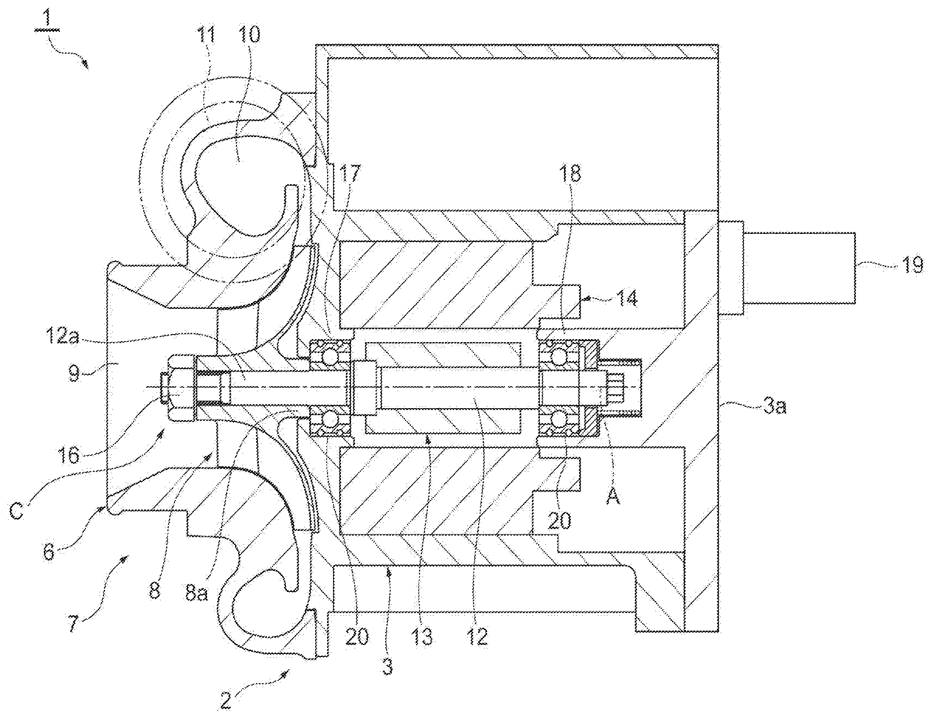
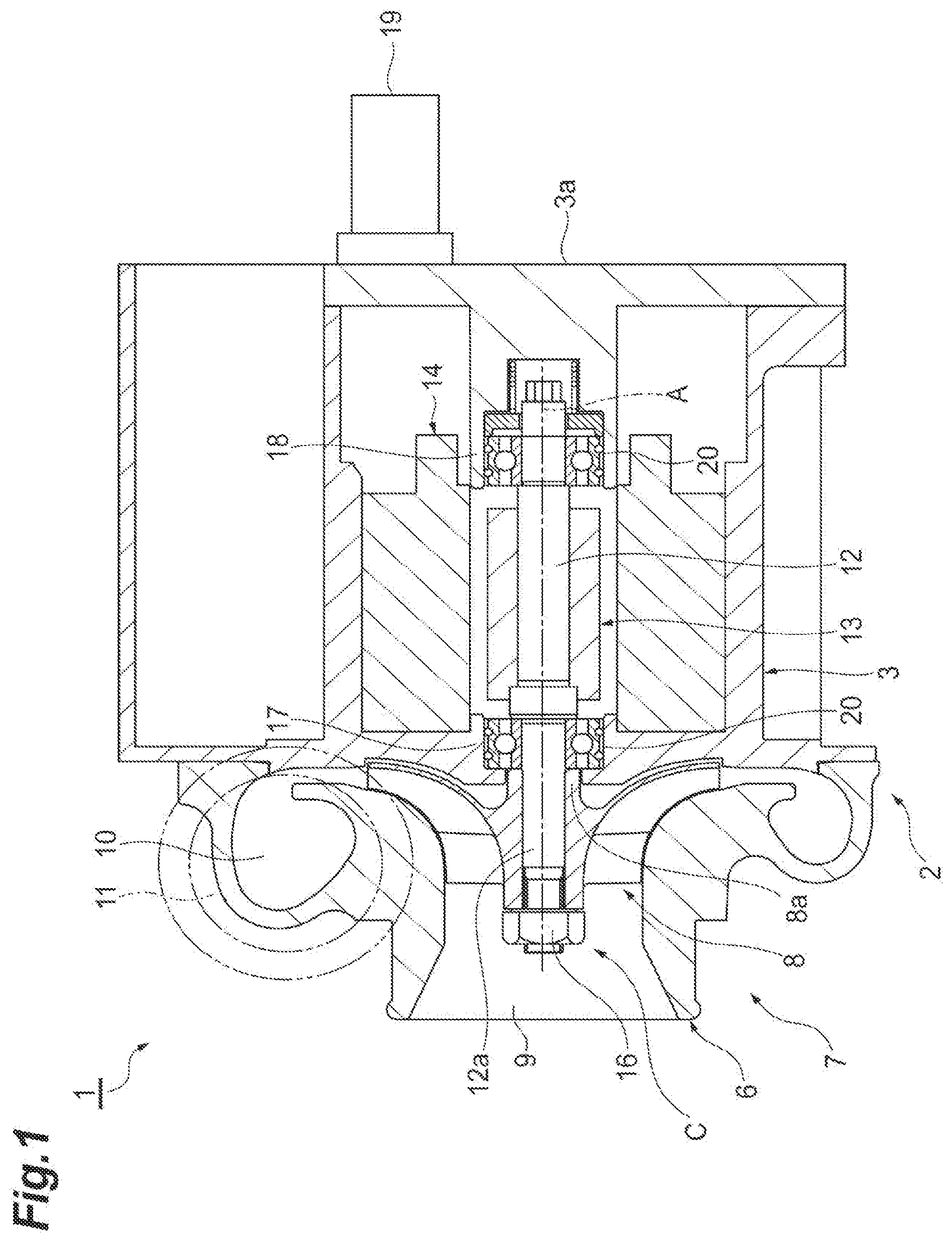
[0009] FIG. 1 is a cross-sectional view illustrating an electric compressor according to an embodiment of the present disclosure.
[0010] FIG. 2 is a partially enlarged cross-sectional view illustrating a bearing structure of FIG. 1.
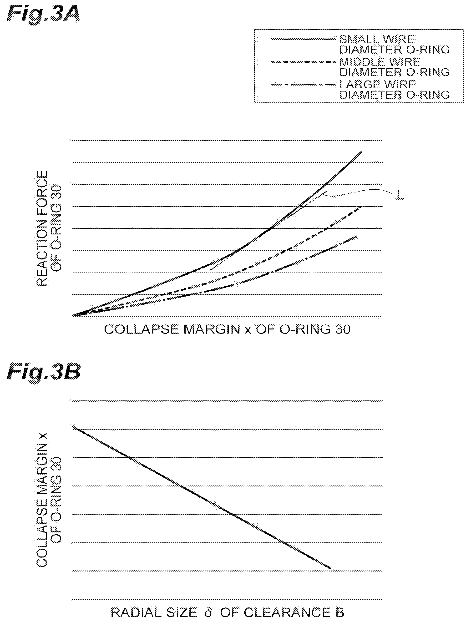
[0011] FIG. 3A is a diagram showing a relationship between a collapse margin of an O-ring and a reaction force of the O-ring and FIG. 3B is a diagram showing a relationship between a clearance and the collapse margin of the O-ring.
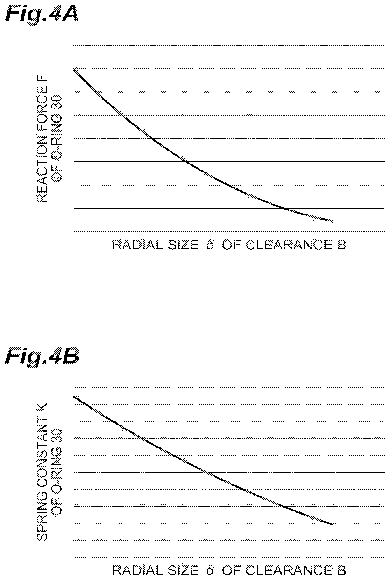
[0012] FIG. 4A is a diagram showing a relationship between a clearance and a reaction force of the O-ring and FIG. 4B is a diagram showing a relationship between the clearance and a spring constant of the O-ring.
[0013] FIG. 5 is a diagram showing a relationship between a clearance and a load displacement amount.
[0014] FIG. 6A is a diagram showing a range of a clearance allowing the O-ring to prevent the rotation of the outer race and FIG. 6B is a diagram showing a range of a clearance capable of reliably preventing the transmission of the vibration.
[0015] FIG. 7 is a diagram in which FIGS. 6A and 6B overlap each other and is a diagram showing a range of a clearance preventing both of the transmission of the vibration and the rotation of the outer race.
DESCRIPTION OF EMBODIMENTS
[0016] An aspect of the present disclosure is a bearing structure for supporting a rotation shaft of a rotation body accommodated in a housing with respect to the housing, including: the rotation shaft; a bearing that is attached in the housing to support the rotation shaft with respect to the housing and includes an inner race through which the rotation shaft is inserted and an outer race which includes an annular groove portion formed on an outer peripheral surface facing an inner wall surface of the housing; and an O-ring which is disposed on the groove portion of the outer race of the bearing, protrudes outward in a radial direction in relation to the outer peripheral surface; and comes into contact with the inner wall surface of the housing, in which a clearance is formed between the inner wall surface of the housing and the outer peripheral surface of the bearing and the clearance is larger than a radial displacement amount of the O-ring.
[0017] According to the bearing structure, the rotation shaft of the rotation body is supported by the bearing structure. The O-ring provided between the outer race of the bearing and the inner wall surface of the housing exhibits the same function as that of a spring. When the rotation body rotates, the radial displacement amount is defined on the basis of the mass of the rotation body and the spring constant of the O-ring. Since the clearance formed between the inner wall surface of the housing and the outer peripheral surface of the bearing is larger than the radial displacement amount of the O-ring, the contact of the outer race of the bearing with respect to the housing is prevented. According to the bearing structure, it is possible to reliably prevent the transmission of the vibration to the housing through the bearing.
[0018] In some aspects, the inner wall surface of the housing, the bearing, and the O-ring are configured such that a frictional force between the inner wall surface of the housing and the O-ring becomes larger than a rotational force of the rotation body. In this case, it is possible to suppress the rotation of the outer race of the bearing when the rotation body rotates.
[0019] An electric compressor according to another aspect of the present disclosure includes a housing, a compressor impeller which is attached to an end portion of the rotation shaft and constitutes a part of the rotation body; and the bearing structure according to claim 1 or 2 for supporting the rotation shaft with respect to the housing. According to the electric compressor, it is possible to prevent the outer race of the bearing from contacting the housing when the rotation body including the compressor impeller rotates. Thus, since it is possible to reliably prevent the transmission of the vibration to the housing through the bearing, it is possible to suppress an occurrence of a vibration or noise in the electric compressor.
[0020] Hereinafter, an embodiment of the present disclosure will be described with reference to the drawings. Additionally, in the description of the drawings, the same reference numerals will be given to the same components and a repetitive description thereof will be omitted. In the description below, a rotation shaft 12 is set as a reference in the case of the "axial direction" or the "radial direction".
[0021] An electric compressor according to an embodiment will be described with reference to FIG. 1. An electric compressor 1 is applied to, for example, an internal combustion engine of a vehicle or a ship. The electric compressor 1 includes a compressor 7. The electric compressor 1 rotates a compressor impeller 8 by an interaction of a rotor portion 13 and a stator portion 14 and compresses a fluid such as air to generate compressed air.
[0022] The electric compressor 1 may be connected to, for example, a turbocharger (not illustrated) applied to an internal combustion engine of a vehicle or a ship. In that case, the electric compressor 1 sends a compressed fluid such as compressed air to a compressor of the turbocharger. By the combination of the electric compressor 1 and the turbocharger, the electric compressor 1 assists the startup of the turbocharger.
[0023] The electric compressor 1 includes the rotation shaft 12 which is rotatably supported inside a housing 2 and the compressor impeller 8 which is fastened to a front end portion 12a of the rotation shaft 12. The housing 2 includes a motor housing 3 which accommodates the rotor portion 13 and the stator portion 14 and an end wall 3a which closes an opening at a second end side (which is the right side of the drawing and is the side opposite to the compressor impeller 8) of the motor housing 3. A compressor housing 6 which accommodates the compressor impeller 8 is provided at a first end side (which is the left side of the drawing and is the side of the compressor impeller 8) of the motor housing 3. The compressor housing 6 includes a suction port 9, a scroll portion 10, and a discharge port 11. For example, an inverter 19 for supplying a current to the stator portion 14 may be provided at the outside of the end wall 3a.
[0024] The rotor portion 13 is attached to a center portion of the rotation shaft 12 in the axial direction and includes one or plural permanent magnets (not illustrated) attached to the rotation shaft 12. The stator portion 14 is attached to an inner surface of the motor housing 3 to surround the rotor portion 13 and includes a coil portion (not illustrated). When an AC current flows to the coil portion of the stator portion 14, the rotation shaft 12 and the compressor impeller 8 rotate together about a rotation axis A by the interaction of the rotor portion 13 and the stator portion 14. When the compressor impeller 8 rotates, the compressor 7 sucks external air through the suction port 9, compresses air through the scroll portion 10, and sends compressed air from the discharge port 11. The compressed air discharged from the discharge port 11 is supplied to the above-described internal combustion engine.
[0025] The electric compressor 1 includes two bearings 20 which rotatably support the rotation shaft 12 with respect to the housing 2. The bearing 20 is attached in the motor housing 3 of the housing 2. The bearing 20 supports the rotation shaft 12 to the motor housing 3 at both ends thereof. The first bearing 20 is provided in a sleeve portion 17 formed at the side of the compressor impeller 8 of the motor housing 3. The second bearing 20 is provided in a sleeve portion 18 protruding from the end wall 3a in the axial direction (toward the compressor impeller 8). For example, the compressor impeller 8 is attached to the rotation shaft 12 by a shaft end nut 16 provided in the front end portion 12a of the rotation shaft 12.
[0026] The rotation shaft 12, the compressor impeller 8 fixed to the rotation shaft 12, the rotor portion 13, and the bearing 20 are integrated with one another inside the housing 2 to constitute a rotation body C. Each of the rotation shaft 12, the compressor impeller 8, the rotor portion 13, and the bearing 20 constitutes a part of the rotation body C. The rotation body C is biased to one side in the axial direction while being accommodated in the motor housing 3. An annular wall surface 17b (see FIG. 2) of the sleeve portion 17 faces and contacts an end surface of the bearing 20 in the axial direction, so that the rotation body C is positioned in the axial direction.
[0027] In the electric compressor 1 of the embodiment, the vibration caused by the rotation of the rotation body C is suppressed. More specifically, the transmission of the vibration of the rotation body C to the housing 2 is prevented, so that the vibration of the electric compressor 1 is suppressed. In order to prevent the transmission of the vibration, the electric compressor 1 has a bearing structure including the bearing 20. The bearing structures provided at two positions of the rotation shaft 12 in the axial direction have the same configuration. Each bearing structure supports the rotation shaft 12 of the rotation body C to the motor housing 3.
[0028] Hereinafter, the first bearing 20 and the bearing structure provided at the first end side will be described. A description of the second bearing 20 and the bearing structure provided at the second end side will be omitted. The arrangement of the second bearing 20 with respect to the sleeve portion 18 may be the same as the arrangement of the first bearing 20 with respect to the sleeve portion 17.
[0029] The bearing 20 is, for example, a ball bearing. More specifically, the bearing 20 is, for example, a grease lubricating type radial bearing. The bearing 20 may be a deep groove bearing or an angular bearing.
[0030] As illustrated in FIG. 2, the bearing 20 includes an inner race 21 through which the rotation shaft 12 is inserted and an outer race 22 which is relatively rotatable with respect to the inner race 21 through a plurality of balls 23. The inner race 21 is press-fitted to, for example, the rotation shaft 12. An inner peripheral surface 21a of the inner race 21 is in contact with an outer peripheral surface 12b of the rotation shaft 12. An end surface at the side of the compressor impeller 8 of the inner race 21 may be in contact with an end surface perpendicular to the rotation axis A of a boss portion 8a of the compressor impeller 8.
[0031] The sleeve portion 17 of the motor housing 3 includes a cylindrical inner peripheral surface (inner wall surface) 17a which faces inwardly in the radial direction. The sleeve portion 17 supports the outer race 22. The outer race 22 includes an outer peripheral surface 22a which faces the inner peripheral surface 17a of the sleeve portion 17 and two annular groove portions 22c which are formed in the outer peripheral surface 22a. The diameter of the outer peripheral surface 22a of the outer race 22 is smaller than that of the inner peripheral surface 17a of the sleeve portion 17. For example, a cylindrical clearance B is formed between the inner peripheral surface 17a of the sleeve portion 17 and the outer peripheral surface 22a of the outer race 22. The end surface at the side of the compressor impeller 8 of the outer race 22 may be in contact with the wall surface 17b perpendicular to the rotation axis A in the annular portion disposed at the outer peripheral side of the boss portion 8a of the compressor impeller 8. Additionally, the shape of the clearance B can be changed in response to the displacement of the rotation body C during the operation of the electric compressor 1.
[0032] Two groove portions 22c are formed to be separated from each other in the axial direction. Each groove portion 22c is continuous to the outer peripheral surface 22a and opens outwardly in the radial direction. An annular O-ring 30 is disposed in each groove portion 22c. The O-ring 30 is directly fitted to the outer race 22. The O-ring 30 is formed of an elastic material. The O-ring 30 is formed of, for example, rubber. The inner peripheral surface of the O-ring 30 fitted to the groove portion 22c is in contact with the bottom surface of the groove portion 22c. A part of the outer peripheral side of the O-ring 30 protrudes outwardly in the radial direction in relation to the outer peripheral surface 22a. An annular outer peripheral end surface which is most distant from the rotation axis A in the O-ring 30 is in contact with the inner peripheral surface 17a of the sleeve portion 17.
[0033] The O-ring 30 has, for example, a circular cross-section in a natural state (a state not receiving any external force) before the O-ring is disposed between the hearing 20 and the sleeve portion 17. The O-ring 30 which is fitted between the groove portion 22c of the bearing 20 and the inner peripheral surface 17a of the sleeve portion 17 is compressed (collapsed). The compressed O-ring 30 has, for example, a non-circular cross-section. The size of the clearance B is set in consideration of the diameter (the wire diameter) of the cross-section of the O-ring 30, the collapse margin of the O-ring 30, and the spring characteristics of the collapsed O-ring 30. The size of the clearance B is not limited to these components and may be set in consideration of, for example, the hardness of the O-ring 30. Additionally, the term of the "collapse margin" is the same concept as the "collapse amount" or the "collapse rate". The term of the "collapse" is the same concept as the "compression".
[0034] Referring to FIGS. 3 to 7, a concept of the size of the clearance B will be described. First, when the O-ring 30 has three kinds of wire diameters as shown in FIG. 3A, a reaction force becomes different in accordance with the wire diameter, the inner diameter, and the hardness even in the same collapse margin. The inclination of the tangent line L of each curve shown in FIG. 3A indicates the spring constant of the O-ring 30.
[0035] This relationship is expressed by the following Equation (1).
[Equation 1]
F=.lamda.*.kappa./D*d0*(ax.sup.2+bx+c) (1)
[0036] Here, F indicates the reaction force of the O-ring 30, x indicates the collapse margin of the O-ring 30, a, b, and c indicate coefficients when the wire diameter of the O-ring 30 is 1 mm (here, the coefficient is different according to the material and/or hardness), D indicates the wire diameter of the O-ring 30, d0 indicates the diameter of the O-ring 30, and k indicates a coefficient.
[0037] Here, the collapse margin x of the O-ring 30 is expressed by the following Equation (2) from the dimensional relationship shown in FIG. 2.
[ Equation 2 ] x = D - Y - X 2 ( 2 ) ##EQU00001##
[0038] Here, X indicates the diameter of the bottom surface of the groove portion 22c and Y indicates the inner diameter of the sleeve portion 17.
[0039] The radial size .delta. of the clearance B is also expressed by the following Equation (3) from the dimensional relationship shown in FIG. 2.
[ Equation 3 ] .delta. = Y - Z 2 ( 3 ) ##EQU00002##
[0040] Here, Z indicates the outer diameter of the outer race 22 (the diameter of the outer peripheral surface 22a).
[0041] From Equations (2) and (3), a relationship between the radial size .delta. of the clearance B and the collapse margin x of the O-ring 30 is expressed by the following Equation (4).
[Equation 4]
x=D-(Y-X)/2=D-(2*.delta.+Z-X)/2 (4)
[0042] Here, when the diameter X of the seat surface of the groove portion 22c, the wire diameter D of the O-ring 30, and the outer diameter Z of the outer race 22 are given values, Equation (4) is expressed as shown in FIG. 3B. Additionally, FIG. 2 illustrates the wire diameter D of the O-ring 30 in a compressed state in order to easily understand the structure with reference to the drawings, but this is not precisely accurate. The wire diameter D is a diameter of the wire portion of the O-ring 30 in a natural state. Further, each of the dimensions X, Y, and Z is a diameter based on the rotation axis A.
[0043] As shown in FIG. 3B, the collapse margin x of the O-ring 30 decreases when the radial size .delta. of the clearance B increases. Further, the spring force of the O-ring 30 decreases when the radial size .delta. of the clearance B increases as shown in FIG. 4A on the basis of the relationship of FIG. 3A and the relationship of FIG. 3B. Furthermore, the frictional force Fr between the O-ring 30 and the inner peripheral surface 17a of the sleeve portion 17 is the product of the frictional coefficient .mu. of the O-ring 30 and the drag force of the spring force F of the O-ring 30 of the rotation shaft 12. Thus, the frictional force Fr also decreases when the spring force F decreases.
[0044] Meanwhile, a value obtained by dividing the frictional torque T.sub.f in the rotation direction generated in the boundary portion between the outer race 22 and the inner race 21 of the bearing 20 in accordance with the rotation of the rotation shaft 12 by the radius R based on the rotation axis A of the outer peripheral surface 22a of the outer race 22 is set as the rotational force Ft. The frictional torque T.sub.f can be changed in accordance with the viscosity v of the grease, the rolling contact friction of the rolling elements, and the like in addition to the rotation speed of the rotation shaft 12.
[0045] Here, a condition that prevents the rotation of the outer race 22 (and the O-ring 30) is that the frictional force Fr is larger than the rotational force Ft. That is, the establishment of the following Equation (5) becomes a first condition.
[Equation 5]
Fr/Ft>1 (5)
[0046] The inner peripheral surface 17a of the sleeve portion 17 of the motor housing 3, the bearing 20, and the O-ring 30 are set such that the frictional force Fr between the inner peripheral surface 17a and the O-ring 30 becomes larger than the rotational force Ft of the rotation body C. In FIG. 6A, the rotation of the outer race 22 is prevented when the clearance is 1.0 or more.
[0047] Meanwhile, since the spring constant K is the inclination of Equation (1) (that is, the differentiation of Equation (1)), the following Equation (6) is established.
[Equation 6]
K=.pi.*.kappa./D*d0*(2ax+b) (6)
[0048] Here, the collapse margin x of the O-ring 30 decreases when the radial size .delta. of the clearance B increases from the relationship (Equation (4)) of FIG. 3B. Further, the spring constant K decreases when the collapse margin x of the O-ring 30 decreases according to Equation (6). Thus, as shown in FIG. 4B, the spring constant K decreases when the clearance B (size .delta.) increases.
[0049] The displacement amount r is expressed by the following Equation (7) from the relationship of M*g*r=1/2*K*r.sup.2.
[ Equation 7 ] r = 2 M g K ( 7 ) ##EQU00003##
[0050] Here, K indicates the spring constant of the O-ring 30, Mg indicates a load applied to the bearing 20 (rotor mass load+eccentric load+vibration load received by the bearing 20), and g indicates gravity acceleration.
[0051] By applying Equations (2) and (6) to Equation (7), the following Equation (8) is established.
[ Equation 8 ] r = 2 M g .pi. .kappa. / D d 0 ( a ( D - ( Y - X ) + b ) ) ( 8 ) ##EQU00004##
[0052] A condition that prevents the outer race 22 from contacting the sleeve portion 17 is that the radial size .delta. of the clearance B is larger than the displacement amount r. Thus, the establishment of the following Equation (9) from Equations (3) and (8) becomes a second condition.
[ Equation 9 ] Y - Z 2 > 2 M g .pi. .kappa. / D d 0 ( a ( D - ( Y - X ) + b ) ) ( 9 ) ##EQU00005##
[0053] The following equation needs to be established according to
[0054] Equation (9).
[ Equation 10 ] .delta. / r = ( ( Y - Z ) / 2 ) / 2 M g .pi. .kappa. / D d 0 ( a ( D - ( Y - X ) + b ) ) > 1 ( 10 ) ##EQU00006##
[0055] This corresponds to a range indicated by the arrow in FIG. 6B.
[0056] As shown in FIG. 4A, when the clearance B increases even in the case of the same load, the spring force decreases and hence the load displacement amount increases. As shown in FIG. 5, in a case in which the displacement amount r (the load displacement amount) becomes larger than the size .delta. of the clearance B, the outer peripheral surface 22a of the outer race 22 of the bearing 20 comes into contact with the inner peripheral surface 17a of the sleeve portion 17 when the load displacement occurs. This may cause a vibration or noise.
[0057] Here, when the relationship (the second condition) shown in Equation (10) is established, the outer peripheral surface 22a of the outer race 22 does not come into contact with the inner peripheral surface 17a of the sleeve portion 17.
[0058] Then, as shown in FIG. 6A, in order to cause the O-ring 30 to stop the rotation of the outer race 22 from the first condition, the range of the clearance needs to be in the range indicated by the arrow of the drawing. Further, as shown in. FIG. 6B, in order to effectively suppress the vibration from the second condition, the range of the clearance needs to be in the range indicated by the arrow of the drawing.
[0059] From FIGS. 6A and 6B, the clearance B of the range indicated by the arrow of FIG. 7 is set in order to realize both of the first condition, that is, the condition of stopping the rotation of the outer race 22 and the second condition, that is, the condition of suppressing the vibration. In the embodiment, the size .delta. of the clearance B is set in the range of realizing both of the rotation stop and the vibration suppression in consideration of the rotation load and the load applied to the O-ring 30 in this way. The point of realizing both of these is the characteristic of the embodiment.
[0060] According to the embodiment, the rotation shaft 12 of the rotation body C is supported by the bearing structure. The O-ring 30 provided between the outer race 22 of the bearing 20 and the inner peripheral surface 17a of the motor housing 3 has the same function as that of the spring with respect to the radial load. When the rotation body C rotates, the radial displacement amount is defined on the basis of the mass, the eccentric load, and the vibration of the rotation body C and the spring constant of the O-ring 30. Since the clearance B formed between the inner peripheral surface 17a of the housing 2 and the outer peripheral surface 22a of the bearing 20 is larger than the radial displacement amount of the O-ring 30, it is possible to prevent the outer race 22 of the bearing 20 from contacting the sleeve portion 17. According to the bearing structure, it is possible to reliably prevent the transmission of the vibration to the housing 2 through the hearing 20. No impact load is applied to the sleeve portion 17 and a damped load is applied thereto.
[0061] In the above-described patent document, there is a document in which the spring force and the rotational friction force of the O-ring are considered. However, regarding the vibration suppression, there is no disclosure on the point of setting the collapse margin of the O-ring by focusing on the relationship between the load displacement amount and the clearance. In the embodiment, since the collision margin of the O-ring 30 is set by focusing on these two points, there is an advantageous effect of compatibility between the vibration reduction and the rotation stop function.
[0062] Since the frictional force between the inner peripheral surface 17a of the housing 2 and the O-ring 30 is larger than the rotational force of the rotation body C, it is possible to suppress the rotation of the outer race 22 of the bearing 20 when the rotation body C rotates. Particularly, in the electric compressor 1 of which the rotation speed can be abruptly increased, it is important to stop the rotation of the outer race 22.
[0063] According to the electric compressor 1, it is possible to prevent the outer race 22 of the bearing 20 from contacting the housing 2 when the rotation body C including the compressor impeller 8 rotates. Thus, since it is possible to reliably prevent the transmission of the vibration to the housing 2 through the bearing 20, it is possible to suppress an occurrence of a vibration or noise in the electric compressor 1.
[0064] Although the embodiment of the present disclosure has been described above, the invention is not limited to the above-described embodiment. For example, two bearings 20 may be provided and one of them may not be provided with the bearing structure. One of two bearings 20 may be omitted. When the bearing structure is provided only at one position, the bearing structure may be provided only at the first end side of the rotation shaft 12 or the second end side of the rotation shaft 12.
[0065] A relationship between the frictional force between the inner peripheral surface 17a and the O-ring 30 and the rotational force of the rotation body C may not satisfy a relationship shown in the above-described embodiment. That is, the bearing structure which satisfies the second condition but does not satisfy the first condition may be employed. Also in this case, it is possible to obtain an effect that the transmission of the vibration to the housing 2 is reliably prevented.
[0066] The cross-sectional shape of the O-ring 30 is not limited to the circular shape.
INDUSTRIAL APPLICABILITY
[0067] According to some aspects of the present disclosure, it is possible to reliably prevent the transmission of the vibration to the housing through the bearing.
REFERENCE SIGNS LIST
[0068] 1: electric compressor, 2: housing, 3: motor housing, 6: compressor housing, 7: compressor, 8: compressor impeller, 12: rotation shaft, 13: rotor portion, 14: stator portion, 17a: inner peripheral surface (inner wall surface), 20: bearing, 21: inner race, 21a: inner peripheral surface, 22: outer race, 22a: outer peripheral surface, 22c: groove portion, 23: ball, 30: O-ring, A: rotation axis, B: clearance, C: rotation body.
* * * * *
D00000
D00001
D00002
D00003
D00004
D00005
D00006
D00007


XML
uspto.report is an independent third-party trademark research tool that is not affiliated, endorsed, or sponsored by the United States Patent and Trademark Office (USPTO) or any other governmental organization. The information provided by uspto.report is based on publicly available data at the time of writing and is intended for informational purposes only.
While we strive to provide accurate and up-to-date information, we do not guarantee the accuracy, completeness, reliability, or suitability of the information displayed on this site. The use of this site is at your own risk. Any reliance you place on such information is therefore strictly at your own risk.
All official trademark data, including owner information, should be verified by visiting the official USPTO website at www.uspto.gov. This site is not intended to replace professional legal advice and should not be used as a substitute for consulting with a legal professional who is knowledgeable about trademark law.