Motor-operated Compressor
HER; Jongtae ; et al.
U.S. patent application number 16/530280 was filed with the patent office on 2020-02-06 for motor-operated compressor. The applicant listed for this patent is LG Electronics Inc.. Invention is credited to Chuljig BAE, Yongkyu CHOI, Jongtae HER, Kitae JANG, Jehoon KIM, Byeongchul LEE, Kyoungjun PARK.
| Application Number | 20200040893 16/530280 |
| Document ID | / |
| Family ID | 67539355 |
| Filed Date | 2020-02-06 |


View All Diagrams
| United States Patent Application | 20200040893 |
| Kind Code | A1 |
| HER; Jongtae ; et al. | February 6, 2020 |
MOTOR-OPERATED COMPRESSOR
Abstract
A motor-operated compressor according to the present disclosure includes a first scroll performing an orbiting motion, a second scroll coupled to the first scroll to form a compression chamber with the first scroll and radially supporting a rotation shaft, a main housing coupled to the second scroll outside the second scroll, and coupled with a driving motor to form a motor chamber, the main housing including an opened end at one side of the motor chamber, a frame portion formed at another side of the motor chamber to axially support the second scroll, and a first bearing portion formed through the frame portion so that the rotation shaft is inserted therethrough to be radially supported, and an inverter housing coupled to the opened end of the main housing to seal the motor chamber, whereby a main frame can be easily formed and a compressor fabrication process can be simplified.
| Inventors: | HER; Jongtae; (Seoul, KR) ; CHOI; Yongkyu; (Seoul, KR) ; PARK; Kyoungjun; (Seoul, KR) ; LEE; Byeongchul; (Seoul, KR) ; KIM; Jehoon; (Seoul, KR) ; BAE; Chuljig; (Seoul, KR) ; JANG; Kitae; (Seoul, KR) | ||||||||||
| Applicant: |
|
||||||||||
|---|---|---|---|---|---|---|---|---|---|---|---|
| Family ID: | 67539355 | ||||||||||
| Appl. No.: | 16/530280 | ||||||||||
| Filed: | August 2, 2019 |
| Current U.S. Class: | 1/1 |
| Current CPC Class: | F04C 2240/10 20130101; F04C 29/028 20130101; F04C 29/045 20130101; F01C 21/02 20130101; F01C 21/007 20130101; F04C 29/023 20130101; F04C 29/047 20130101; F04C 2240/30 20130101; F04C 2240/20 20130101; F04C 2240/805 20130101; F01C 19/005 20130101; F04C 18/0215 20130101; F04C 27/008 20130101 |
| International Class: | F04C 18/02 20060101 F04C018/02; F04C 29/02 20060101 F04C029/02 |
Foreign Application Data
| Date | Code | Application Number |
|---|---|---|
| Aug 3, 2018 | KR | 10-2018-0090941 |
| Aug 3, 2018 | KR | 10-2018-0090942 |
Claims
1. A compressor, comprising: a driving motor comprising a stator and a rotor; a rotation shaft coupled to the rotor; a first scroll located at a side of the driving motor and configured to perform an orbiting motion based on rotation of the rotation shaft, the rotation shaft extending in an axial direction and being eccentrically coupled to the first scroll; a second scroll that is coupled to the first scroll and that defines a compression chamber together with the first scroll; a main housing that is coupled to an outside of the second scroll, that is coupled to the driving motor, and that defines a motor chamber that accommodates the driving motor, the main housing comprising: an opened end portion located at a first side of the motor chamber, a frame portion that is located at a second side of the motor chamber and that is configured to support the second scroll in the axial direction, and a first bearing portion that extends through at least a portion of the frame portion in the axial direction, that is configured to receive the rotation shaft, and that is configured to support the rotation shaft in a radial direction; and an inverter housing that accommodates an inverter element electrically connected to the driving motor and that is coupled to the opened end portion of the main housing to seal the motor chamber.
2. The compressor of claim 1, wherein the frame portion comprises a first protrusion that protrudes from a side of the frame portion in the radial direction, the first protrusion defining a first passage that extends through the first protrusion and that is configured to communicate with the motor chamber, wherein the second scroll is coupled to an axial end surface of the frame portion, wherein the second scroll comprises a second protrusion that protrudes in the radial direction from a side of the second scroll corresponding to the first protrusion, the second protrusion defining a second passage that extends through the second protrusion toward the frame portion, and wherein the second passage has a first end in communication with the first passage and a second end in communication with the compression chamber.
3. The compressor of claim 1, wherein a distance from a center of the stator in the axial direction to a first end defined at the opened end portion is less than a distance from the center of the stator in the axial direction to a second end defined at the frame portion.
4. The compressor of claim 3, wherein the rotation shaft passes through the first scroll and is rotatably coupled to the second scroll, and wherein the rotation shaft defines an oil supply passage that passes through an inside of the rotation shaft in the axial direction and that is configured to communicate with an oil guide passage defined at the second scroll.
5. The compressor of claim 4, wherein the second scroll comprises a second bearing portion configured to rotatably accommodate an end portion of the rotation shaft, wherein the second bearing portion extends outward of the end portion of the rotation shaft in the axial direction and defines an oil guide space between the end portion of the rotation shaft and the second bearing portion, and wherein the oil guide passage is configured to communicate with the oil guide space.
6. The compressor of claim 5, wherein the second scroll comprises a third protrusion that protrudes from a rear surface of the second scroll in the axial direction, and wherein the third protrusion extends in the radial direction and defines the oil guide passage therein.
7. The compressor of claim 5, further comprising a rear housing that is coupled to the second scroll, the rear housing comprising a third protrusion that protrudes from an inner surface of the rear housing in the axial direction toward the second scroll, and wherein the third protrusion extends in the radial direction and defines the oil guide passage therein.
8. The compressor of claim 4, wherein the rotation shaft further defines a plurality of oil supply holes that extend from the oil supply passage toward an outer circumferential surface of the rotation shaft and that are configured to communicate with bearing surfaces located at the second scroll, the first scroll, and the frame portion.
9. The compressor of claim 8, wherein the frame portion and the first scroll face each other and define a back-pressure chamber located between the frame portion and the first scroll and configured to communicate with the plurality of oil supply holes, and wherein the back-pressure chamber is configured to communicate with the motor chamber through a gap defined between the outer circumferential surface of the rotation shaft and an inner circumferential surface of the frame portion.
10. The compressor of claim 1, wherein the inverter housing comprises a sealing surface portion corresponding to the opened end portion of the main housing, and wherein the compressor further comprises a coupling member that is located between the main housing and the sealing surface portion of the inverter housing and that is configured to couple the opened end portion of the main housing and the sealing surface portion of the inverter housing to each other.
11. The compressor of claim 10, wherein the coupling member comprises a plurality of rivets that protrude in the axial direction from the opened end portion of the main housing and that are arranged along a circumferential direction of the main housing with predetermined intervals, and wherein the plurality of rivets are configured to pass through the inverter housing based on coupling the main housing and the inverter housing to each other.
12. The compressor of claim 10, wherein the coupling member comprises a plurality of rivets that are press-fitted into the opened end portion of the main housing in the axial direction and that are arranged along a circumferential direction of the main housing with predetermined intervals, and wherein the plurality of rivets are configured to couple to the main housing through the inverter housing.
13. The compressor of claim 10, wherein the coupling member comprises bolts configured to couple to the opened end portion of the main housing through the inverter housing.
14. The compressor of claim 10, wherein the sealing surface portion comprises a sealing protrusion that protrudes from a side of the sealing surface portion toward the main housing, that has an annular shape, and that is inserted into the opened end portion of the main housing.
15. The compressor of claim 14, further comprising a sealing member located between the main housing and the inverter housing, wherein the sealing member comprises: a first sealing portion located between the opened end portion of the main housing and the sealing surface portion of the inverter housing, the first sealing portion defining a plurality of holes configured to receive the coupling member; and a second sealing portion located between an inner circumferential surface of the main housing and an outer circumferential surface of the sealing protrusion of the inverter housing.
16. The compressor of claim 15, wherein the first sealing portion and the second sealing portion are integrally formed with each other.
17. A compressor comprising: a main housing that defines a motor chamber therein, the main housing comprising an open ended portion that defines an opening at a first side of the main housing; a driving motor located in the motor chamber, the driving motor comprises a stator coupled to an inside of the main housing and a rotor disposed radially inside of the stator and configured to rotate relative to the stator; an inverter housing that is coupled to the first side of the main housing and that covers the opening of the main housing; a rotation shaft that is coupled to the rotor and that passes through and extends outward of a second side of the main housing in an axial direction; a first scroll that is located at the second side of the main housing, that is coupled to the rotation shaft, and that is configured to perform an orbiting motion based on rotation of the rotation shaft; and a second scroll that is coupled to the first scroll, that defines a compression chamber together with the first scroll, and that is coupled to the second side of the main housing, wherein the second scroll is disposed outside of the main housing and defines at least a portion of an exterior of the compressor.
18. The compressor of claim 17, wherein the main housing further comprises: a frame portion that is located at the second side of the main housing and that is configured to support the second scroll in the axial direction; and a first bearing portion that extends through at least a portion of the frame portion in the axial direction, that is configured to receive the rotation shaft, and that is configured to support the rotation shaft in a radial direction.
19. The compressor of claim 17, wherein the main housing further comprises a first protrusion that protrudes radially outward from the second side of the main housing and that faces the second scroll in the axial direction, the first protrusion defining a first passage that extends through the first protrusion in the axial direction and that is configured to communicate with the motor chamber, wherein the second scroll comprises a second protrusion that protrudes radially outward from an outer circumference of the second scroll corresponding to the first protrusion, the second protrusion defining a second passage that extends through the second protrusion, and wherein the second passage has a first end in communication with the first passage and a second end in communication with the compression chamber.
20. The compressor of claim 19, wherein the second passage extends in a direction inclined with respect to the first passage.
Description
CROSS-REFERENCE TO RELATED APPLICATION
[0001] Pursuant to 35 U.S.C. .sctn. 119(a), this application claims the benefit of an earlier filing date of and the right of priority to Korean Application No. 10-2018-0090941 and Korean Application No. 10-2018-0090942, filed on Aug. 3, 2018, the contents of which are incorporated by reference herein in their entirety.
BACKGROUND OF THE DISCLOSURE
1. Field of the Disclosure
[0002] The present disclosure relates to a motor-operated compressor operated by a motor.
2. Description of the Related Art
[0003] As a motor-operated compressor, a scroll compression type suitable for a high compression ratio operation is widely known. In the scroll type motor-operated compressor (hereinafter, abbreviated as "motor-operated compressor"), a motor part configured as a driving motor is installed in a hermetic casing, and a compression part configured by a fixed scroll and an orbiting scroll is disposed at one side of the motor part. The motor part and the compression part are connected to each other by a rotation shaft so that a rotational force of the motor part is transferred to the compression part.
[0004] Such a motor-operated compressor is provided with an inverter module, which may be installed on a radial side surface of the casing or on an axial side surface of the casing. Recently, a motor-operated compressor has been introduced in which an inverter module is installed on an axial side surface of a casing in consideration of heat dissipation of the inverter module. Prior art [Korean Patent Laid-Open Publication No. 10-2016-0104398 (Published Date: Sep. 5, 2016)] discloses an example in which an inverter module is installed on an axial side surface of a compressor casing.
[0005] The motor-operated compressor according to the prior art has a structure in which one end of a housing is opened and another end is closed. A compression part including a center head constituting a main frame is installed on the opened end, and an inverter casing constituting the inverter module is installed on the closed end. As a result, the motor part and the compression part are sequentially inserted from the opened end to the closed end.
[0006] However, in the prior art motor-operated compressor as described above, the center head constituting the main frame is separately manufactured and assembled into the housing. Accordingly, a process of manufacturing the center head and a process of assembling the center head are required, which causes an increase in an overall fabrication process of the compressor. In addition, a machining error occurs during the manufacturing of the center head or an assembly error occurs during the assembling, and thereby concentricity between the motor part and the compression part is misaligned. As a result, friction loss and bearing wear are increased during rotation of a rotation shaft.
[0007] In addition, in the related art motor-operated compressor, as the center head is inserted into the housing, an outer diameter of the center head may be limited by an inner diameter of the housing. In this case, an outer diameter of the compression part is reduced relative to the same inner diameter of the housing, which causes a limitation in expanding compressor capacity.
[0008] In addition, in the related art motor-operated compressor, the center of the housing and the center of the motor part are located on the same axial line, but this causes a size increase compared to the compressor capacity. In other words, a suction passage is usually formed in the vicinity of the edge of the center head. However, if the center of the housing and the center of the driving unit are located on the same axial line, the outer diameter of the center head must be increased by the suction passage. If the outer diameter of the center head is increased, the inner diameter of the housing also becomes large, which results in increasing the size of the compressor.
[0009] In addition, in the related art motor-operated compressor, as one end directed to the inverter side, of both ends of the housing, is closed and another end directed to the compression part side is opened, the driving motor constituting the motor part is inserted from the opened end of the housing. As a result, an inserted depth of the motor part becomes long and thereby the assembling work of the motor part becomes difficult. As the inserted depth of the motor part is increased, there is a fear that concentricity of the motor part may be misaligned.
[0010] In the related art motor-operated compressor, a gasket is provided between a main housing and an inverter housing. However, since such a gasket is formed in the shape of an annular plate, a sealing area is limited by thickness of the housing. As a result, if the thickness of the housing is thin, the sealing area becomes small, and thus the thickness of the housing must be increased or a coupling force must be increased.
[0011] In addition, in the related art motor-operated compressor, an oil supply hole is formed sequentially through a fixed scroll and the center head so as to communicate with a side surface of a back-pressure chamber, so that oil separated in an oil separation chamber can be guided into the back-pressure chamber. However, the oil supply hole is difficult to be formed because it should usually penetrate sequentially through the fixed scroll and the center head. Also, this makes the oil supply hole located far from bearings, which causes a limitation in quickly supplying oil to bearing surfaces.
[0012] Further, in the related art motor-operated compressor, when the back-pressure chamber is sealed, a kind of stagnation pressure is formed in the back-pressure chamber, so that the oil cannot flow smoothly into the back-pressure chamber and friction loss of the main bearing is caused.
[0013] In addition, in the related art motor-operated compressor, coupling portions protrude from outer circumferential surfaces of the housing and the rear head or the housing and the inverter casing, and both coupling protrusions are coupled by bolts. This brings about an increase in outer diameter of the compressor, which results in increasing the weight of the compressor and requiring a wide space for installing the compressor.
[0014] In the related art motor-operated compressor, a gasket is provided between the housing and a rear head for covering the housing. However, the gasket is formed in the shape of an annular plate so that the sealing area is narrowed. Accordingly, there is a problem that the thickness of the housing or the rear head or the coupling force must be increased in order to seal an inner space of the housing.
[0015] In the related art motor-operated compressor, coupling surfaces between the housing and a member coupled to the housing are formed flat, which makes it difficult to accurately assemble the housing and the member coupled to the housing.
SUMMARY
[0016] One aspect of the present disclosure is to provide a motor-operated compressor, capable of simplifying a fabrication process for a main frame supporting an orbiting scroll.
[0017] In relation to the one aspect, the present disclosure provides a motor-operated compressor, capable of easily aligning concentricity between a motor part and a compression part by reducing a machining error or assembly error due to a main frame, and of reducing friction loss and bearing wear with respect to a rotation shaft.
[0018] In relation to the one aspect, the present disclosure provides a motor-operated compressor, capable of increasing compressor capacity compared to the same outer diameter of a main frame.
[0019] In relation to the one aspect, the present disclosure provides a motor-operated compressor, capable of enhancing the degree of design freedom for a suction passage without increasing an outer diameter of a housing or a main frame.
[0020] Another aspect of the present disclosure is to provide a motor-operated compressor, capable of facilitating assembly of a driving motor by reducing an inserted depth of the driving motor constituting a motor part.
[0021] In relation to another aspect, the present disclosure provides a motor-operated compressor, capable of easily aligning concentricity between a housing and a driving motor when assembling the driving motor to the housing.
[0022] In relation to another aspect, the present disclosure provides a motor-operated compressor, capable of enhancing a heat dissipation effect of an inverter element by reducing a gap between a main housing and an inverter housing.
[0023] Still another aspect of the present disclosure is to provide a motor-operated compressor, capable of enhancing sealing force for a motor chamber by securing a sufficient sealing area between a main housing and an inverter housing.
[0024] Still another aspect of the present disclosure is to provide a motor-operated compressor, capable of quickly supplying oil separated in an oil separation chamber into a back-pressure chamber and simplifying a structure of an oil supply hole for the oil supply.
[0025] In relation to the still another aspect, the present disclosure provides a motor-operated compressor, in which pressure in a back-pressure chamber forms flow pressure and simultaneously oil can be supplied to bearing surfaces quickly and smoothly.
[0026] Still another aspect of the present disclosure is to provide a motor-operated compressor, capable of increasing sealing force for an inner space of a main housing by increasing a sealing area between the main housing and a member coupled to the main housing for sealing the inner space of the main housing.
[0027] Still another aspect of the present disclosure is to provide a motor-operated compressor, capable of preventing an increase in weight or size of the compressor by simplifying a coupling structure between a main housing and a member coupled to the main housing.
[0028] Still another aspect of the present disclosure is to provide a motor-operated compressor, capable of aligning assembled positions of a main housing and an inverter housing by forming a stepped surface on the inverter housing coupled to the main housing.
[0029] To achieve these and other advantages and in accordance with the purpose of this specification, as embodied and broadly described herein, there is provided a motor-operated compressor, including a main housing having a motor chamber, a driving motor fixed to an inside of the main housing, a fixed scroll coupled to the main housing outside the main housing, an orbiting scroll engaged with the fixed scroll at the outside of the main housing to form a compression chamber, and an inverter housing coupled to the main housing to seal the motor chamber.
[0030] Here, the main housing may be provided with a frame portion integrally extending therefrom so as to support the orbiting scroll in an axial direction.
[0031] The frame portion may be formed to have a different center of axis from that of the driving motor.
[0032] The inverter housing may be provided with a sealing protrusion inserted into the main housing, and a sealing member may be disposed between an outer circumferential surface of the sealing protrusion and an inner circumferential surface of the main housing.
[0033] To achieve these and other advantages and in accordance with the purpose of this specification, as embodied and broadly described herein, there is provided a motor-operated compressor, including a main housing having an inner space, in which one end thereof in an axial direction is opened and another end in the axial direction has a frame portion, a driving motor having a stator inserted into the inner space of the main housing and a rotor rotatably provided inside the stator, a rotation shaft having one end coupled to the rotor of the driving motor and another end inserted through the frame portion to be supported by the frame portion in a radial direction, a first scroll supported in the axial direction by the frame portion of the main housing and eccentrically coupled to the rotation shaft to perform an orbiting motion, a second scroll coupled to the main housing at outside of the inner space of the main housing and engaged with the first scroll to form a compression chamber, a rear housing coupled to the second scroll to form an oil separation chamber together with the second scroll, and an inverter housing coupled to the main housing to seal the opened end of the main housing, wherein a first protrusion and a second protrusion are formed on outer circumferential surfaces of the frame portion and the second scroll, respectively, in the radial direction. The first protrusion may be provided with a first passage communicating with the inner space of the main housing and the second protrusion may be provided with a second passage communicating with the compression chamber. The first passage and the second passage may communicate with each other so that the inner space of the main housing communicates with the compression chamber therethrough.
[0034] Further, in order to achieve the aspects of the present invention, there is provided a motor-operated compressor, including a driving motor having a stator and rotor, a rotation shaft coupled to the rotor, a first scroll which is provided on one side of the driving motor, and through which the rotation shaft is eccentrically coupled in an axial direction, the first scroll performing an orbiting motion by the rotation shaft, a second scroll coupled to the first scroll to form a compression chamber together with the first scroll, the rotation shaft rotatably inserted into the second scroll through the first scroll to be supported in a radial direction, a main housing coupled to the second scroll outside the second scroll, and coupled with the driving motor to form a motor chamber constituting a suction space, the main housing provided with an opened end at one side of the motor chamber, a frame portion formed at another side of the motor chamber to support the second scroll in the axial direction, and a first bearing portion formed through the frame portion so that the rotation shaft is inserted therethrough to be supported in the radial direction, and an inverter housing accommodating therein an inverter element electrically connected to the driving motor, and coupled to the opened end of the main housing to seal the motor chamber. A coupling portion for coupling the opened end of the main housing and a sealing surface portion of the inverter housing facing the opened end of the main housing may be provided between the main housing and the sealing surface portion of the inverter housing.
[0035] Further, in order to achieve the aspect of the present invention, there is provided a motor-operated compressor, including a driving motor having a stator and a rotor, a rotation shaft coupled to the rotor, a first scroll which is provided on one side of the driving motor, and through which the rotation shaft is eccentrically coupled in an axial direction, the first scroll performing an orbiting motion by the rotation shaft, a second scroll coupled to the first scroll to form a compression chamber together with the first scroll, a main housing coupled to the second scroll outside the second scroll, and coupled with the driving motor to form a motor chamber constituting a suction space, the main housing provided with an opened end at one side of the motor chamber, a frame portion formed at another side of the motor chamber to support the second scroll in the axial direction, and a first bearing portion formed through the frame portion so that the rotation shaft is inserted therethrough to be supported in a radial direction, and an inverter housing accommodating therein an inverter element electrically connected to the driving motor, and coupled to the opened end of the main housing to seal the motor chamber.
[0036] Here, the frame portion may be provided with a first protrusion on one side thereof in a radial direction, and the first protrusion may be provided with a first passage formed therethrough to communicate with inside of the motor chamber. The second scroll may be coupled to an axial end surface of the frame portion. The second scroll may be provided with a second protrusion protruding therefrom in the radial direction, the second protrusion may be provided with a second passage formed therethrough, and the second passage may have another end communicating with the compression chamber.
[0037] Here, when the opened end of the main housing is a first end and the another end provided with the frame portion is a second end, a length from a center of the stator in the axial direction to the first end may be shorter than a length from the center of the stator in the axial direction to the second end.
[0038] The rotation shaft may be rotatably coupled to the second scroll through the first scroll and may be provided with an oil supply passage formed therein in the axial direction. The second scroll may be provided with an oil guide passage communicating with the oil supply passage of the rotation shaft.
[0039] The second scroll may be provided with a second bearing portion in which an end portion of the rotation shaft is rotatably accommodated, the second bearing portion may have an oil guide space therein, extending in the axial direction to be longer than the end portion of the rotation shaft, and the oil guide passage may communicate with the oil guide space.
[0040] The second scroll or a rear housing coupled to the second scroll may be provided with a third protrusion protruding therefrom in the axial direction, and the third protrusion may be provided with the oil guide passage therein.
[0041] The oil supply passage may be provided with a plurality of oil supply holes formed toward an outer circumferential surface of the rotation shaft in a penetrating manner, to communicate with bearing surfaces of the second scroll, the first scroll, and the frame portion, respectively.
[0042] A back-pressure chamber communicating with the plurality of oil supply holes may be formed between surfaces of the frame portion and the first scroll that face each other. The back-pressure chamber may communicate with the motor chamber through a gap between an outer circumferential surface of the rotation shaft and an inner circumferential surface of the frame portion.
[0043] The inverter housing may be provided with a sealing surface portion corresponding to the opened end of the main housing, and a coupling portion for coupling the opened end of the main housing and the sealing surface portion of the inverter housing to each other may be provided between the main housing and the sealing surface portion of the inverter housing.
[0044] The coupling portion may be configured as a plurality of rivets extending in the axial direction from the opened end of the main housing and formed at predetermined intervals along a circumferential direction.
[0045] The plurality of rivets may be coupled through the inverter housing.
[0046] Here, the coupling portion may be configured as a plurality of rivets press-fitted into the opened end of the main housing in the axial direction and formed at predetermined intervals along a circumferential direction, and the plurality of rivets may be coupled through the inverter housing.
[0047] The coupling portion may be configured as bolts coupled to the opened end of the main housing through the inverter housing.
[0048] The sealing surface portion may be provided with a sealing protrusion protruding from one side thereof into an annular shape, and the sealing protrusion may be inserted into the opened end of the main housing.
[0049] A sealing member may be provided between the main housing and the inverter housing, and the sealing member may include a first sealing portion located between the opened end of the main housing and the sealing surface portion of the inverter housing and having a plurality of holes through which the coupling portion is inserted, and a second sealing portion located between an inner circumferential surface of the main housing and an outer circumferential surface of the sealing protrusion of the inverter housing.
[0050] The first sealing portion and the second sealing portion may be integrally formed with each other.
[0051] In a motor-operated compressor according to the present disclosure, by forming a frame portion integrally with a main housing, formation of a main frame can be facilitated so as to simplify a fabrication process of the compressor.
[0052] In addition, by forming the frame portion integrally with the main housing, a machining error and an assembly error of the main frame can be reduced. Accordingly, concentricity matching between a motor part and a compression part can be facilitated, and friction loss and bearing wear during rotation of a rotation shaft can be reduced.
[0053] Also, by forming the frame portion integrally with the main housing, an outer diameter of the frame portion can increase compared with the same outer diameter of the main housing. This may result in realizing a compressor with large capacity as compared with the same outer diameter
[0054] A suction passage can be formed by extending a part of the main housing provided with the frame portion, without increasing the entire main housing. Thus, the degree of design freedom for the suction passage can be enhanced even without increasing the size of the compressor.
[0055] Also, in a motor-operated compressor according to the present disclosure, one end, to which an inverter housing is coupled, of both ends of a main housing, can be opened so that a driving motor can be inserted, thereby reducing a depth by which the driving motor is inserted. This can make it easy to assemble the driving motor.
[0056] In addition, the insertion depth of the driving motor can be reduced, so that concentricity of the driving motor and the main housing can be kept constant when assembling the driving motor.
[0057] Further, a heat dissipation effect of an inverter element can be improved by reducing a gap between a main housing and an inverter housing.
[0058] Also, in a motor-operated compressor according to the present disclosure, a sealing protrusion can be formed between a main housing and an inverter housing, thereby increasing a sealing area for a motor chamber while applying a sealing member providing good sealing force. This may result in enhancing a sealing effect.
[0059] In a motor-operated compressor according to the present disclosure, a rotation shaft can communicate with an oil separation chamber via a compression part, and an oil supply passage for guiding oil separated in the oil separation chamber to a back-pressure chamber can be formed in the rotation shaft, thereby simplifying the oil supply passage for guiding the oil separated in the oil separation chamber into the back-pressure chamber.
[0060] As the oil supply passage communicates directly with each bearing surface, the oil can be quickly supplied to the bearing surfaces, thereby enhancing an oil supply effect.
[0061] As a motor chamber and the back-pressure chamber communicate with each other, flow pressure is generated in the back-pressure chamber. This can make the oil smoothly supplied to the back-pressure chamber and each bearing surface.
[0062] In a motor-operated compressor according to the present disclosure, a first end of a main housing and a sealing surface portion of an inverter housing in contact with the first end of the main housing can be coupled by inserting rivets or bolts therethrough. Accordingly, the first end of the main housing and the sealing surface portion of the inverter housing can be coupled to each other even without forming coupling protrusions on respective outer circumferential surfaces of the main housing and the inverter housing. Accordingly, the outer diameter of the compressor can be reduced compared with the case where the coupling protrusions are formed on the outer circumferential surfaces of the main housing and the inverter housing to couple the both housings, which may result in reducing the weight of the compressor and decreasing the space required for installing the compressor.
[0063] In a motor-operated compressor according to the present disclosure, a sealing member configured as a gasket can be provided between a main housing and an inverter housing, and the sealing member is provided with a first sealing portion and a second sealing portion to seal outer circumferential surfaces of a sealing surface portion and a sealing protrusion, respectively. Accordingly, the sealing area can be increased without increasing the thicknesses of the main housing and the inverter housing, thereby sealing the motor chamber more effectively.
[0064] In a motor-operated compressor according to the present disclosure, a sealing protrusion can be formed in a stepped manner on an inverter housing coupled to a main housing, thereby easily aligning an installation position of the inverter housing when the inverter housing is assembled to the main housing. Accordingly, the operation of assembling the main housing and the inverter housing can be performed easily and accurately.
[0065] Also, in a motor-operated compressor according to the present disclosure, by forming a frame portion integrally with a main housing, formation of a main frame can be facilitated so as to simplify a fabrication process of the compressor.
[0066] Also, in a motor-operated compressor according to the present disclosure, one end, to which an inverter housing is coupled, of both ends of a main housing, can be opened so that a driving motor can be inserted, thereby reducing a depth by which the driving motor is inserted. This can make it easy to assemble the driving motor.
BRIEF DESCRIPTION OF THE DRAWING
[0067] FIG. 1 is a perspective view illustrating a compressor module and an inverter module disassembled from each other in a motor-operated compressor in accordance with an embodiment of the present disclosure.
[0068] FIG. 2 is a sectional view illustrating an inside of the motor-operated compressor according to FIG. 1.
[0069] FIG. 3 is a sectional view of a main housing, viewed from a side, in the motor-operated compressor according to FIG. 2.
[0070] FIG. 4 is a front view of the main housing in FIG. 3, viewed from the rear.
[0071] FIG. 5 is a sectional view illustrating a rotation shaft and bearings supporting the rotation shaft in accordance with an embodiment of the present disclosure.
[0072] FIG. 6 is a sectional view of a second scroll in accordance with an embodiment of the present disclosure, viewed from a side.
[0073] FIG. 7 is a front view of the second scroll according to FIG. 6, viewed from the front.
[0074] FIG. 8 is a planar view illustrating an engagement relationship between an orbiting wrap and a fixed wrap in a non-involute shape in a motor-operated compressor according to an embodiment of the present disclosure.
[0075] FIG. 9 is an enlarged sectional view of a coupled portion between a main housing and an inverter housing in FIG. 2.
[0076] FIG. 10 is a schematic view illustrating a circulation process of refrigerant and oil in accordance with an embodiment of the present disclosure.
[0077] FIG. 11 is an exploded perspective view illustrating another embodiment of an assembly structure of a compressor module and an inverter module, in a motor-operated compressor according to the present disclosure.
[0078] FIG. 12 is a sectional view illustrating an inside of the motor-operated compressor according to FIG. 11.
[0079] FIG. 13 is an enlarged sectional view of a coupled portion between a main housing and an inverter housing in FIG. 12.
[0080] FIG. 14 is a sectional view illustrating another embodiment of a rivet coupling structure in FIG. 13.
[0081] FIGS. 15 and 16 are sectional views illustrating embodiments of a coupling structure of the main housing and the inverter housing in FIG. 13.
[0082] FIGS. 17 and 18 are sectional views illustrating different embodiments of a sealing member in FIG. 13.
DETAILED DESCRIPTION
[0083] Description will now be given in detail of a motor-operated compressor according to exemplary embodiments disclosed herein, with reference to the accompanying drawings.
[0084] FIG. 1 is a perspective view illustrating a compressor module and an inverter module disassembled from each other in a motor-operated compressor in accordance with an embodiment of the present disclosure, and FIG. 2 is a sectional view illustrating an inside of the motor-operated compressor according to FIG. 1.
[0085] As illustrated in FIGS. 1 and 2, a scroll type motor-operated compressor (hereinafter, abbreviated as a motor-operated compressor) according to an embodiment of the present disclosure may include a compressor module 101 for compressing a refrigerant, and an inverter module 201 coupled to a front side of the compressor module 101 for controlling an operation of the compressor module 101. The compressor module 101 and the inverter module 201 may be successively assembled, or independently manufactured and assembled. This embodiment illustrates the latter as a representative example, but the former and the latter may alternatively be combined such that the compressor module and the inverter module are independently manufactured but successively assembled.
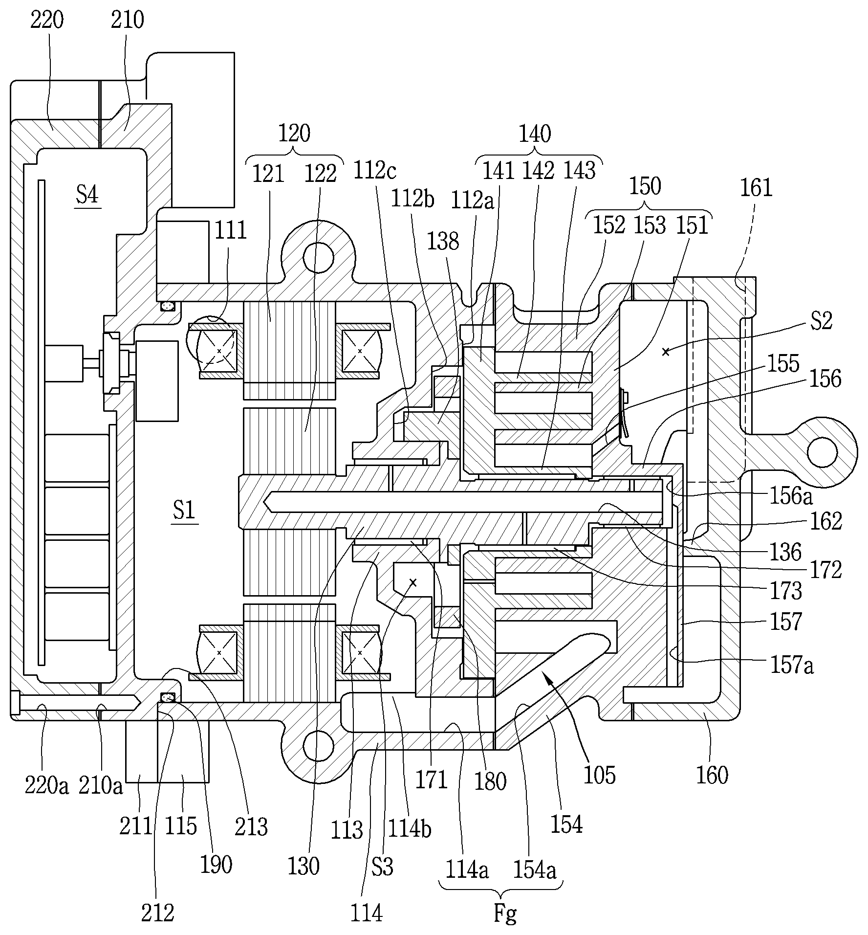
[0086] The compressor module 101 includes a main housing 110 having an inner space forming a motor chamber S1 and provided with an inlet port 111 formed thereat to communicate with the motor chamber S1, a driving motor 120 as a motor part fixed to the motor chamber S1 of the main housing 110, a compression part 105 provided at one side of the driving motor 120 outside the main housing 110 to compress a refrigerant using a rotational force of the driving motor 120, and a rear housing 160 coupled to another side of the compression part 105 to form an oil separation chamber S2.
[0087] As the main housing 110 is arranged in a horizontal direction with respect to the ground, the driving motor 120 and the compression part 105 are also arranged in the horizontal direction. For the sake of explanation, a left side of FIG. 2 is designated as a front side and a right side as a rear side.
[0088] The main housing 110 has a cross-section in a cup-like shape in which a front end is opened and a rear end is partially closed. The opened front end of the main housing 110 is sealed by being coupled to an inverter housing 210 to be described later and a frame portion 112 supporting the compression part 105 integrally extends from the closed rear end of the main housing 110. A first bearing portion 113 is formed through the frame portion 112 of the main housing 110. A main bearing portion 132 of a rotation shaft 130 to be described later penetrates through the first bearing portion 113 so as to be rotatably supported.
[0089] A first bearing 171 as a bush bearing may be inserted into the first bearing portion 113. An inner circumferential surface of the first bearing portion 113 may be spaced apart from the main bearing portion 132 of the rotation shaft 130 so that a back-pressure chamber S3 to be described later can communicate with the motor chamber S1. As the inlet port 111 to which a suction pipe (not shown) is connected is formed near the front end of the main housing 110, the motor chamber S1 of this embodiment forms a kind of suction space. Accordingly, the motor-operated compressor according to the embodiment of the present disclosure is implemented as a low-pressure type compressor in the aspect that refrigerant is introduced into the compression part through the inner space of the main housing constituting the motor chamber.
[0090] The main housing according to the embodiment of the present disclosure is integrally formed with the frame portion, as described above. Accordingly, a process of separately assembling a frame to a main housing is excluded, thereby reducing the number of assembling steps and simultaneously enhancing assembling performance of the driving motor.
[0091] FIG. 3 is a sectional view of a main housing, viewed from a side, in the motor-operated compressor according to FIG. 2, and FIG. 4 is a front view of the main housing in FIG. 3, viewed from the rear.
[0092] As illustrated in FIGS. 3 and 4, an axial center Ob1 of the first bearing portion 113 is formed to be aligned with an axial center Om of the driving motor 120. To this end, a center of an outer diameter and a center of an inner diameter (i.e., the center of the first bearing portion) of the frame portion 112 may be aligned with each other.
[0093] However, the axial center Ob1 of the first bearing portion 113 may be aligned with the axial center Om of the driving motor 120 but the center Oi of the outer diameter and the center Oo of the inner diameter of the frame portion 112 may not be aligned with each other. For example, as illustrated in FIGS. 3 and 4, a first protrusion 114 may protrude from one side of the frame portion 112 in a radial direction of the frame portion 112, and a first passage 114a may be formed through the first protrusion 114 to communicate with an inside of the motor chamber S1. The first passage 114a may form a suction passage Fg together with a second passage 154a of a second scroll 150 to be described later, so that the compression chamber V and the motor chamber S1 can communicate with each other.
[0094] On the other hand, the frame portion 112 is formed such that its front side protrudes toward a center side, that is, in a direction in which the first bearing portion 113 faces the driving motor 120, and its rear side is recessed to be stepped at least twice in a direction toward the driving motor 120. Also, the frame portion 112 is provided at its rear side with a scroll mounting groove 112a in which an orbiting end plate of a first scroll to be explained later is inserted to be supported in an axial direction, an Oldham ring mounting groove 112b for mounting an Oldham ring 180 therein which is a rotation-preventing mechanism, and a balance weight accommodating groove 112c for rotatably accommodating a balance weight 138 therein. The scroll mounting groove 112a, the Oldham ring mounting groove 112b, and the balance weight accommodating groove 112c are continuously formed in a stepped manner so as to form a kind of back-pressure chamber S3.
[0095] The rear end of the first bearing portion 113 protrudes in a direction toward a first scroll 140 and is formed into a cylindrical shape. A first bearing 171 which is configured as a bush bearing is inserted into the first bearing portion 113. Accordingly, an outer circumferential surface of the rear end of the first bearing portion 113 forms the balance weight accommodating groove 112c, thereby forming the back-pressure chamber S3.
[0096] The rear end of the first bearing portion 113 is provided with an axial bearing surface 113a forming a thrust surface together with an axial bearing protrusion 135 of the rotation shaft to be described later. Here, at least one of the axial bearing surface 113a of the first bearing portion 113 or an axial bearing portion 135a of the axial bearing protrusion 135 provided on the rotation shaft 130 may be provided with an oil passage groove 113b. With this configuration, as oil or refrigerant in the back-pressure chamber S3 flows toward the motor chamber S1 along the axial bearing surfaces, flow pressure is formed in the back-pressure chamber S3.
[0097] On the other hand, the driving motor 120 includes a stator 121 fixed to an inner circumferential surface of the main housing 110, and a rotor 122 positioned inside the stator 121 and rotated by interaction with the stator 121. The rotor 122 is coupled with the rotation shaft 130 that transfers the rotation force of the driving motor 120 to the compression part 105 while rotating together with the rotor 122.
[0098] The stator 121 is inserted and fixed to the main housing 110 in a heat shrinking (or hot pressing) manner. Accordingly, by reducing the depth of insertion in the main housing 110, the stator 121 may be easily assembled and may be advantageous in view of maintaining its concentricity during the shrinking process.
[0099] To this end, as illustrated in FIG. 3, if it is assumed that the opened end of the main housing 110 is a first end 110a and an end provided with the frame portion 112 is a second end 110b, a length L1 from a center CL of the stator 121 of an axial direction of the stator 121 to the first end 110a may be shorter than a length L2 from the center CL of the stator 121 to the second end 110b. Accordingly, as described above, an insertion depth L3 by which the stator 121 is inserted into the motor chamber S1 of the main housing 110 can be shortened.
[0100] On the other hand, the rotation shaft 130 is coupled to a center of the rotor 122 in the heat shrinking (or hot pressing) manner. Both ends of the rotation shaft 130 with respect to the driving motor 120 may also be supported in a radial direction. However, as in the embodiment of the present disclosure, one end of the rotation shaft 130 may be a fixed end which is supported at one side of the driving motor 120, namely, at two points in the radial direction by the frame portion 112 and the second scroll 150, and another end of the rotation shaft 130 coupled to the rotor 122 of the driving motor 120 may be a free end in the radial direction.
[0101] FIG. 5 is a sectional view illustrating a rotation shaft and bearings supporting the rotation shaft in accordance with an embodiment of the present disclosure.
[0102] As illustrated in FIG. 5, the rotation shaft 130 includes a shaft portion 131 coupled to the rotor 122, a main bearing portion 132 rotatably supported in the first bearing portion 113 in the radial direction, an eccentric portion 133 eccentrically coupled to the first scroll 140, and a sub bearing portion 134 rotatably supported radially in a second bearing portion 156 of a second scroll 150 in the radial direction. The main bearing portion 132 and the sub bearing portion 134, as aforementioned, support the rotation shaft 130 in the radial direction, respectively. The eccentric portion 133 transfers rotational force of the driving motor 120 to the first scroll 140, so that the first scroll 140 performs an orbiting motion by an Oldham ring 180.
[0103] The axial bearing protrusion 135 may extend radially from a middle portion of the rotation shaft 130, namely, between the main bearing portion 132 and the eccentric portion 133. The axial bearing surface 135a of the axial bearing portion 135 forms a thrust surface together with the axial bearing surface 113a of the first bearing portion 113.
[0104] An oil supply passage 136 is formed in the rotation shaft 130 by a predetermined depth in a direction from the rear end toward the front end. Oil supply holes 137a, 137b, and 137c are formed through a middle portion of the oil supply passage 136 toward outer circumferential surfaces of the main bearing portion 132, the eccentric portion 133, and the sub bearing portion 134, respectively. It will be described again later together with an oil supply structure.
[0105] On the other hand, the compression part 105, as aforementioned, includes an orbiting scroll (hereinafter, referred to as a first scroll) 140 supported by the frame portion 112 of the main housing 110 in the axial direction to perform an orbiting motion, and a fixed scroll (or a non-orbiting scroll) (hereinafter, referred to as a second scroll) 150 engaged with the first scroll 140 and fixed to the closed second end 110b of the main housing 110. A pair of compression chambers V is formed between the first scroll 140 and the second scroll 150 during the orbiting motion of the first scroll 140. The compression chambers will be described later with an orbiting wrap and a fixed wrap.
[0106] The first scroll 140 is axially supported by the frame portion 112, and an Oldham ring 180 which is a rotation-preventing mechanism for preventing a rotation of the first scroll 140 is provided between the frame portion 112 and the first scroll 140. The rotation-preventing mechanism may also be configured as a pin & ring type as well as the Oldham ring.
[0107] The first scroll 140 is provided with an orbiting scroll end plate (hereinafter, referred to as an orbiting end plate) 141 in a substantially disk shape. An orbiting wrap 142 is formed on a front surface of the orbiting end plate 141. The orbiting wrap 142 is engaged with a fixed wrap 153 to be explained later so as to form compression chambers at an inner surface and an outer surface with respect to the fixed wrap 153. The orbiting wrap will be explained later with the fixed wrap.
[0108] The orbiting end plate 141 is provided with a back-pressure hole 141a for communicating the back-pressure chamber S3 and an intermediate compression chamber V with each other. Accordingly, oil or refrigerant can flow between the back-pressure chamber S3 and the intermediate compression chamber V according to a pressure difference between the back-pressure chamber S3 and the intermediate compression chamber V.
[0109] A rotation shaft coupling portion 143 to which the eccentric portion 133 of the rotation shaft 130 is rotatably coupled is formed through a center of the orbiting end plate 141. The rotation shaft coupling portion 143 is formed in a cylindrical shape, and a third bearing 173 forming a bearing surface together with the eccentric portion 133 of the rotation shaft 130 is inserted into the rotation shaft coupling portion 143. The rotation shaft coupling portion 143 (or the third bearing) is formed so as to overlap the orbiting wrap 142 in a radial direction. The rotation shaft coupling portion 143 becomes a portion of the orbiting wrap 142 which is located at the innermost position.
[0110] On the other hand, the second scroll is coupled to the second end of the main housing from outside of the main housing, as described above. In this case, a sealing member such as a gasket may be provided between the main housing and the second scroll.
[0111] FIG. 6 is a sectional view of a second scroll in accordance with an embodiment of the present disclosure, viewed from a side, and FIG. 7 is a front view of the second scroll according to FIG. 6, viewed from the front.
[0112] As illustrated in FIGS. 6 and 7, the second scroll 150 includes a fixed scroll end plate (hereinafter, referred to as a fixed end plate) 151 formed in a substantially disk shape, and a side wall portion 152 formed at an edge of the fixed end plate 151 to be coupled to a frame-side end portion of the main housing 110. A fixed wrap 153 which is engaged with the orbiting wrap 142 to form compression chambers is formed on a front surface of the fixed end plate 151. The fixed wrap 153 may be formed in an involute shape together with the orbiting wrap 142, but may also be formed in various other shapes. The shape of the fixed wrap 153 will be described later together with the orbiting wrap 142, with reference to FIG. 8.
[0113] A second protrusion 154 radially protrudes from an outer circumferential surface of the side wall portion 152 so as to correspond to the first protrusion 114. The second protrusion 154 may be provided therein with a second passage 154a forming the suction passage Fg together with the first passage 114a. Accordingly, a center Obo of an outer diameter of the second scroll 150 may be different from a center Ob2 of a second bearing portion 156.
[0114] The second passage 154a forming the suction passage Fg may be formed in the axial direction or may be formed to be inclined as illustrated in FIG. 6. If the second passage 154a is formed in the axial direction, an outer diameter of the fixed end plate 151 may be enlarged to increase a winding length of a fixed wrap 153, compared to the same outer diameter of the main housing 110. On the other hand, if the second passage 154a is formed to be inclined, the winding length of the fixed wrap 153 may be reduced, compared with the same capacity of the compression chamber, so as to downsize the compressor.
[0115] The first passage 114a and the second passage 154a forming the suction passage Fg are formed in the first protrusion 114 and the second protrusion 154, respectively, and thus the suction passage Fg may be formed close to an outer circumferential surface of the compressor. Accordingly, a refrigerant sucked into the compression chamber V through the suction passage Fg from the motor chamber S1 can quickly exchange heat with external air of the compressor, which may lower a specific volume of the refrigerant sucked into the compression chamber V, thereby reducing suction loss. Particularly, in the case of the second passage 154a, since the second scroll 150 is provided outside the main housing 110, the second passage 154a may be located closer to the outside, as compared with being inserted into the main housing 110. This may result in further enhancing a heat dissipation effect of refrigerant which has been slightly heated while passing through the motor chamber.
[0116] Further, a dimple groove 152a may be formed on the outer circumferential surface of the side wall portion 152 to reduce a weight of the second scroll 150 and simultaneously prevent deformation of the second scroll 150. The dimple groove 152a may be provided in plurality arranged along a circumferential direction with predetermined intervals, or one dimple groove 152a may be formed long in the circumferential direction.
[0117] Since the outer circumferential surface of the side wall portion 152 of the second scroll 150 is located outside the main housing 110, an outer diameter of the second scroll 150 may be greater than or equal to an inner diameter of the main housing 110. Therefore, the outer diameter of the second scroll 150 can increase on the basis of the same outer diameter of the compressor, which may result in extending the winding lengths of the fixed wrap 153 and the orbiting wrap 142, thereby increasing a suction volume of the compression chamber V.
[0118] An outlet port 155 which communicates a final compression chamber V with an oil separation chamber S2, which is to be explained later, so as to guide a discharge of a refrigerant is formed through a central portion of the fixed end plate 151. The outlet port 155 may be formed in a penetrating manner from the compression chamber V to the oil separation chamber S2 in an axial direction or inclined direction of the fixed end plate 151. As illustrated in FIG. 8, only one outlet port 155 may be formed to communicate a first compression chamber V1 and a second compression chamber V2 to be explained later, or a first outlet port 155a and a second outlet port 155b may be formed to communicate with the first compression chamber V1 and the second compression chamber V2, respectively.
[0119] A second bearing portion 156 may be formed in the center of the fixed end plate 151, so that the sub bearing portion 134 of the rotation shaft 130 is rotatably inserted therein to be supported in a radial direction. The second bearing portion 156 may be formed by extending from the fixed end plate 151 toward a rear housing 160 in an axial direction, or by more increasing thickness of the fixed end plate 151. However, in the latter case, not only a weight of the second scroll 150 is increased but also an unnecessary portion is thickly formed, and thereby a length of the outlet port 155 may become long, thereby increasing a dead volume. Therefore, the second bearing portion 156 is formed by protruding a part of the fixed end plate 151 as illustrated in the former case. For example, it is preferable that a third protrusion 157 is formed at a portion of the fixed end plate 151, except for the portion where the outlet port 155 is formed, and the second bearing portion 156 is formed in the third protrusion 157.
[0120] The second bearing portion 156 is formed in a cylindrical shape having a closed rear surface, and a second bearing 172, which forms the bearing surface together with the sub bearing portion 134 of the rotation shaft 130, is coupled to an inner circumferential surface of the second bearing portion 156 in an inserted manner. The second bearing 172 may be implemented as a bush bearing or a needle bearing.
[0121] An oil guide space 156a more extending in the axial direction than an end portion of the rotation shaft 130 is formed in a rear side of the second shaft accommodating portion 156. The oil guide space 156a is located between an oil guide passage 157a and an oil supply passage 136 to be explained later. The oil guide passage 157a may communicate with the oil separation chamber S2, and the oil supply passage 136 may communicate with the bearing surfaces provided on the outer circumferential surfaces of the main bearing portion 132, the sub bearing portion 134, and the eccentric portion 133, respectively.
[0122] The oil guide passage 157a may be formed in the second scroll 150 or in the rear housing 160, which will be described later. For example, in the case where the oil guide passage 157a is formed in the second scroll 150, if it is assumed that the rear surface of the second scroll 150, that is, one side surface facing the frame portion 112, of both side surfaces of the second scroll 150 in the axial direction is a first surface 150a and an opposite surface to the first surface 150a is a second surface 150b, the third protrusion 157 may protrude from the second surface 150b in a direction toward the rear housing 160, and the oil guide passage 157a may be formed in the third protrusion 157 in the radial direction of the second scroll 150. One end of the oil guide passage 157a may communicate with an outer circumferential surface of the fixed end plate 151 and another end of the oil guide passage 157a may communicate with an inner circumferential surface of the oil guide space 156a.
[0123] Accordingly, oil of high pressure, separated from a refrigerant in the oil separation chamber S2 of the rear housing 160 can quickly flow to the oil guide space 156a along the oil guide passage 157a by a pressure difference, and then may be quickly supplied to each bearing surface through the oil supply passage 136 and the respective oil supply holes 137a to 137c by the pressure difference.
[0124] Referring back to FIG. 5, one oil supply passage 136 and a plurality of oil supply holes 137a, 137b, and 137c may be formed in the rotation shaft 130. The oil supply passage 136, as aforementioned, is formed in the axial direction by a predetermined depth from an end portion of the rotation shaft 130, namely, from the rear end to the front end of the rotation shaft 130 accommodated in the oil guide space 156a. The plurality of oil supply holes 137a, 137b and 137c may be formed at predetermined intervals in a middle portion of the oil supply passage 136 along the axial direction.
[0125] The plurality of oil supply holes 137a, 137b and 137c may include a second oil supply hole 137b penetrating from the oil guide passage 136 to an outer circumferential surface of the sub bearing portion 134, a third oil supply hole 137c penetrating from the oil guide passage 136 to an outer circumferential surface of the eccentric portion 133, and a first oil supply hole 137a penetrating from the oil supply passage 136 to an outer circumferential surface of the main bearing portion 132.
[0126] Accordingly, oil introduced into the oil supply passage 136 from the oil guide space 156a passes sequentially through the second oil supply hole 137b, the third oil supply hole 137c and the first oil supply hole 137a, so as to be supplied to the respective bearing surfaces.
[0127] On the other hand, each of the orbiting wrap and the fixed wrap may be formed in an involute shape. However, as shown in this embodiment, when the rotation shaft is coupled through the center of the second scroll as the orbiting scroll, the final compression chamber may be formed at an eccentric position, and thereby a great pressure difference may be generated between the compression chambers. This is because, in the case of a shaft-through scroll compressor, pressure of one compression chamber becomes much lower than pressure of another compression chamber as the final compression chamber is formed eccentrically from a center of a scroll. Therefore, in the shaft-through scroll compressor, it is advantageous to form the orbiting wrap and the fixed wrap into a non-involute shape as shown in this embodiment.
[0128] FIG. 8 is a planar view illustrating an engagement relationship between an orbiting wrap and a fixed wrap in a non-involute shape in a motor-operated compressor according to an embodiment of the present disclosure.
[0129] As illustrated in FIG. 7, an orbiting wrap 142 according the embodiment of the present disclosure may have a shape in which a plurality of arcs having different diameters and origins are connected, and the outermost curve may be formed in a substantially elliptical shape having a major axis and a minor axis. A fixed wrap 153 may be formed in a similar manner.
[0130] A rotation shaft coupling portion 143 which forms an inner end portion of the orbiting wrap 142 and to which the eccentric portion 133 of the rotation shaft 130 is rotatably inserted may be formed through a central portion of the orbiting end plate 141 in an axial direction. A third bearing 173 implemented as a bush bearing may be fixedly inserted into an inner circumferential surface of the rotation shaft coupling portion 143. An outer circumferential part of the rotation shaft coupling portion 143 is connected to the orbiting wrap 142 to form the compression chamber V together with the fixed wrap 153 during a compression process.
[0131] Furthermore, the rotation shaft coupling portion 143 may be formed at a height overlapping with the orbiting wrap 142 on the same plane, and thus the eccentric portion 133 of the rotation shaft 130 may be disposed at a height overlapping with the orbiting wrap 142 on the same plane. Accordingly, a repulsive force and a compressive force of a refrigerant can be attenuated by each other while being applied to the same plane based on an orbiting end plate, thereby preventing an inclination of the first scroll 140 due to an action of the compressive force and repulsive force.
[0132] The rotation shaft coupling portion 143 is provided with a concave portion 143a formed on an outer circumferential part thereof, which faces an inner end portion of the fixed wrap 153, and engaged with a protrusion 153a of the fixed wrap 153 to be explained later. An increasing portion 143b which increases in thickness from an inner circumferential part to the outer circumferential part of the rotation shaft coupling portion 143 is formed at an upstream side along a direction that a compression chamber V is formed. This may extend a compression path of the first compression chamber V1 immediately before discharge, and consequently a compression ratio of the first compression chamber V1 can be increased close to a compression ratio of the second compression chamber V2.
[0133] At another side of the concave portion 335 is formed an arcuate compression surface 143c having an arcuate shape. A diameter of the arcuate compression surface 143c is decided by a thickness of the inner end portion of the fixed wrap 153 (i.e., a thickness of a discharge end) and an orbiting radius of the orbiting wrap 142. When the thickness of the inner end portion of the fixed wrap 153 increases, a diameter of the arcuate compression surface 143c increases. As a result, a thickness of the orbiting wrap around the arcuate compression surface 143c may increase to ensure durability, and the compression path may extend to increase the compression ratio of the second compression chamber V2 to that extent.
[0134] In addition, the protrusion 153a is formed near the inner end portion (a suction end or a start end) of the fixed wrap 153 corresponding to the rotation shaft coupling portion 143 in a manner of protruding toward the outer circumferential part of the rotation shaft coupling portion 143. The protrusion 153a may be provided with a contact portion 153b protruding therefrom to be engaged with the concave portion 143a. In other words, the inner end portion of the fixed wrap 153 may be formed to have a larger thickness than other portions. As a result, wrap strength at the inner end portion of the fixed wrap 153, which is subjected to the highest compressive force on the fixed wrap 323, may increase so as to enhance durability.
[0135] On the other hand, the compression chamber V may be formed between the fixed end plate 151 and the fixed wrap 153 and the orbiting wrap 142 and the orbiting end plate 141, and a suction chamber, an intermediate pressure chamber, and an oil separation chamber may be formed consecutively along a proceeding direction of the wraps.
[0136] The compression chamber V may include a first compression chamber V1 formed between an outer surface of the orbiting wrap 142 and an inner surface of the fixed wrap 153, and a second compression chamber V2 formed between an inner surface of the orbiting wrap 152 and an outer surface of the fixed wrap 153. In other words, the first compression chamber V1 includes a compression chamber formed between two contact points P11 and P12 generated in response to the inner surface of the fixed wrap 153 being brought into contact with the outer surface of the orbiting wrap 142, and the second compression chamber V2 includes a compression chamber formed between two contact points P21 and P22 generated in response to the outer surface of the fixed wrap 153 being brought into contact with the inner surface of the orbiting wrap 142.
[0137] Here, when an angle having a larger value between angles formed by two lines connecting the center of the eccentric portion, that is, the center O of the rotation shaft coupling portion, and the two contact points P11, P12 is .alpha., the first compression chamber V1 immediately before discharge has .alpha.<360.degree. immediately before at least the start of discharge, and a distance I between normal vectors at the two contact points P11, P12 also has a value larger than zero.
[0138] As a result, the first compression chamber immediately before the discharge, which is formed by the fixed wrap and the orbiting wrap according to the embodiment of the present disclosure, may have a smaller volume than that formed by a fixed wrap and an orbiting wrap having an involute shape. Therefore, the compression ratios of the first and second compression chambers V1 and V2 can all be improved even without increasing the size of the first wrap 142 and the second wrap 153.
[0139] Meanwhile, the rear housing 160 is coupled to the second surface 150b of the second scroll 150. As the rear housing 160 is coupled to the second surface 150b of the second scroll 150, the oil separation chamber S2 may be formed such that a refrigerant discharged from the compression chamber V is accommodated therein.
[0140] Here, separate protrusions (not shown), like a main side coupling protrusion 115 and an inverter side coupling protrusion 211 to be described later, are formed respectively on the outer circumferential surfaces of the rear housing 160 and the second scroll 150, so as to be coupled to each other by bolts, or a coupling bolt passing through an edge surface of the rear housing 160 may be coupled to an edge surface of the second scroll 150. A sealing member such as a gasket may be provided between the rear housing 160 and the second scroll 150.
[0141] The rear housing 160 is provided with an exhaust port 161 communicating with a discharge pipe. The rear housing 160 may also be provided therein with a support protrusion 162 protruding toward the third protrusion 157 of the second scroll 150 so as to support the second scroll 150 in the axial direction. The support protrusion 162 is in close contact with the second surface 150b of the second scroll 150, more precisely, the third protrusion 157 so as to support the second scroll 150 toward the first scroll 140.
[0142] Meanwhile, an inverter housing 210 may be coupled in a covering manner to one of both ends of the main housing 110, which is opposite to the rear housing 160, namely, coupled to the opened front end of the main housing 110.
[0143] Referring back to FIGS. 1 and 2, the inverter housing 210 constitutes a part of an inverter module 201. The inverter housing 210 forms an inverter chamber S4 together with an inverter cover 220. The inverter chamber S4 accommodates therein inverter components 230 such as a substrate and an inverter element, and the inverter housing 210 and the inverter cover 220 are coupled to each other by bolts. The inverter cover 220 may be assembled to the inverter housing 210 after the inverter housing 210 is first assembled to the main housing 110, or the inverter housing 210 may be assembled to the main housing 110 after being assembled to the inverter cover 220. The former and the latter may differ depending on a method of assembling the inverter housing 210 to the main housing 110.
[0144] FIG. 9 is an enlarged sectional view of a coupled portion between a main housing and an inverter housing in FIG. 2. As illustrated in FIG. 9, a coupling groove 210a may be formed in an edge surface of an inverter housing 210, and a coupling hole 220a may be formed in an edge of an inverter cover 220. The inverter housing 210 and the inverter cover 220 may be assembled by a bolt which is inserted through the coupling hole 220a to be coupled to the coupling groove 210a.
[0145] At least one inverter side coupling protrusion 211 may be formed on an outer circumferential surface of the inverter housing 210 and at least one main side coupling protrusion 115 may be formed on an outer circumferential surface of the main housing 110 to correspond to the inverter side coupling protrusion 211. The inverter side coupling protrusion 211 and the main side coupling protrusion 115 may be provided with a coupling hole 211a and a coupling groove 115a, respectively, so that the inverter housing 210 can be assembled to the main housing 110 by a bolt.
[0146] In this case, after the inverter module 201 is assembled first by coupling the inverter housing 210 and the inverter cover 220, the inverter module 201 may be coupled later to the main housing 110 constituting the compressor module 101. With this configuration, the inverter module can be easily assembled and also an inverter element constituting the inverter module can be closely adhered on or disposed close to a side surface of the inverter housing, thereby enhancing a heat dissipation effect of the inverter element.
[0147] When the motor chamber S1 of the main housing 110 is sealed by coupling the inverter housing 210 to the main housing 110, a gap between the main housing 110 and the inverter housing 210 must be tightly sealed in order to prevent leakage of refrigerant.
[0148] To this end, a gasket may be disposed between surfaces at which the main housing 110 and the inverter housing 210 face each other in the axial direction, namely, a front surface of the main housing 110 and a rear surface of the inverter housing 210, so as to closely adhere the main housing 110 and the inverter housing 210 to each other in the axial direction. However, when the motor chamber S1 is sealed by installing the gasket between the front surface of the main housing 110 and the rear surface of the inverter housing 210, a sealing area is determined by thickness of the main housing 110 and thickness of the inverter housing 210. Therefore, the thicknesses of the main housing 110 and the inverter housing 210 must be increased to secure sealing force.
[0149] Therefore, a sealing member may be inserted between the main housing 110 and the inverter housing 210 to seal the motor chamber S1, thereby enhancing sealing force. For example, as illustrated in FIG. 9, a sealing surface portion 212 that the first end of the main housing 110 faces may be formed on a rear surface of the inverter housing 210, a sealing protrusion 213 constituting a fourth protrusion may be formed at an inner side of the sealing surface portion 212 to be inserted into an inner circumferential surface of the main housing 110, and an O-ring as a sealing member 190 may be inserted between an outer circumferential surface of the sealing protrusion 213 and an inner circumferential surface of an opened end of the main housing 110 which are in contact with each other.
[0150] The sealing surface portion 212 forms a rear surface of the inverter housing 210 which is in contact with the first end 110a as the front surface of the main housing 110. It is advantageous in terms of sealing efficiency that the gasket described above is provided between the sealing surface portion 212 and the first end 110a of the main housing 110 or the sealing surface portion 212 and the first end 110a of the main housing are closely adhered on each other even if a gasket is not provided.
[0151] The sealing protrusion 213 may be formed in an annular shape and have a predetermined height and thickness within a range that does not interfere with the driving motor 120. A sealing groove 213a in which the O-ring as the sealing member 190 is inserted may be formed on the outer circumferential surface of the sealing protrusion 213. The sealing groove 213a may also be formed on the inner circumferential surface of the main housing 110. However, when the sealing member 190 is the O-ring, it is advantageous in terms of assembly characteristics that the sealing member 215 is inserted into the outer circumferential surface of the sealing protrusion 213.
[0152] It is preferable in terms of enhancing sealing force with the main housing 110 that the sealing groove 213a has a depth shorter than a diameter of the sealing member 190 and thus a part of the O-ring as the sealing member 190 protrudes from the sealing groove 213a.
[0153] Oil and refrigerant may circulate in the motor-operated compressor according to the embodiment of the present invention as follows. FIG. 10 is a schematic view illustrating a circulation process of refrigerant and oil in accordance with an embodiment of the present disclosure.
[0154] That is, when power is applied to the driving motor 120, the rotation shaft 130 transfers a rotational force to the first scroll 140 while rotating together with the rotor 122, and the first scroll 140 performs an orbiting motion by the Oldham ring 180. Then, the compression chamber V is reduced in volume while continuously moving toward a center.
[0155] A refrigerant is then introduced into the motor chamber S1 as the suction space through the inlet port 101a. The refrigerant introduced into the motor chamber S1 flows through a passage formed between the outer circumferential surface of the stator 121 and the inner circumferential surface of the main housing 110 or a gap between the stator 121 and the rotor 122. Such refrigerant is then introduced into the compression chamber V through the suction passage Fg formed in the main housing 110 and the second scroll 150.
[0156] The refrigerant is compressed by the first scroll 140 and the second scroll 150 and discharged to the oil separation chamber S2 through the outlet port 155. This refrigerant is separated from oil in the oil separation chamber S2. The refrigerant is discharged to a refrigeration cycle through an exhaust port 161 while the oil is supplied to each bearing surface through the oil guide passage 157a, the oil guide space 156a, the oil supply passage 136 and the oil supply holes 137a to 137c which constitute an oil supply path. The oil is partially introduced into the back-pressure chamber S3 so as to form back pressure supporting the first scroll 140 toward the second scroll 150.
[0157] The first scroll 140 is supported in a direction toward the second scroll 150 by the back pressure of the back-pressure chamber S3, so that the compression chamber V between the first scroll 140 and the second scroll 150 is sealed. At this time, the oil in the back-pressure chamber S3 partially flows into the compression chamber V through the back-pressure hole 141a provided at the orbiting end plate 141 while partially being introduced into the motor chamber S1 through a gap between the main bearing portion 132 and the first bearing 171 such that the back-pressure chamber S3 forms flow pressure. Such series of processes are repetitively performed.
[0158] As such, in the motor-operated compressor according to the present disclosure, by forming the frame portion integrally with the main housing, the formation of the main frame can be facilitated so as to simplify the fabrication process of the compressor and also a machining process and an assembly process of the main frame can be eliminated so as to reduce a machining error or assembly error. Also, concentricity alignment can be facilitated between the motor part and the compression part, friction loss and bearing wear of the rotation shaft can be reduced, and an outer diameter of the frame portion compared with the same outer diameter of the main housing can be increased, thereby implementing a compressor with large capacity as compared with the same outer diameter. The suction passage can be formed by extending a part of the main housing provided with the frame portion, thereby enhancing the degree of design freedom for the suction passage.
[0159] In the motor-operated compressor according to the present disclosure, one end, to which the inverter housing is coupled, of both ends of the main housing, can be opened so that the driving motor can be inserted, thereby reducing a depth by which the driving motor is inserted. This makes it easy to assemble the driving motor and to constantly align concentricity between the driving motor and the main housing when the driving motor is assembled. In addition, an interval between the main housing and the inverter housing can be reduced to increase a heat dissipation effect of an inverter element, and simultaneously the inverter housing and the inverter cover can be modularized so as to increase the degree of assembly of the inverter element.
[0160] Also, in the motor-operated compressor according to the present disclosure, the sealing protrusion can be formed between the main housing and the inverter housing, thereby increasing a sealing area. A sealing member providing good sealing force can be interposed between the sealing protrusion and the main housing, thereby enhancing a sealing effect.
[0161] In the motor-operated compressor according to the present disclosure, the rotation shaft having the oil supply passage can communicate with the oil separation chamber via the compression part, thereby simplifying the oil supply passage for guiding oil separated in the oil separation chamber into the back-pressure chamber. The oil separated in the oil separation chamber can be quickly supplied to the bearing surfaces, thereby reducing the friction loss. The motor chamber and the back-pressure chamber can communicate with each other so as to form flow pressure in the back-pressure chamber, thereby allowing the oil to be smoothly supplied to the bearing surfaces.
[0162] Meanwhile, as described above, the main housing and a member coupled to the main housing are normally coupled using bolts, but in this case, a structure for coupling the bolts is additionally constituted, which results in increasing the outer diameter of the compressor. For example, in the prior art, coupling portions 200a, (not shown) are formed on outer circumferential surfaces of the housing 200 and the rear head 300, or on outer circumferential surfaces of the housing 200 and the inverter casing 130, respectively, and coupled by bolts. This is because, as described above, the coupling portion protrudes from the outer circumferential surface of each member, and thereby the overall size of the compressor increases.
[0163] In an embodiment according to the present disclosure, the main housing and the inverter housing are coupled without forming the coupling protrusions on the outer circumferential surfaces of the both housings.
[0164] FIG. 11 is an exploded perspective view illustrating another embodiment of an assembly structure of a compressor module and an inverter module, in a motor-operated compressor according to the present disclosure, FIG. 12 is a sectional view illustrating an inside of the motor-operated compressor according to FIG. 11, and FIG. 13 is an enlarged sectional view of a coupled portion between a main housing and an inverter housing in FIG. 12.
[0165] As illustrated in FIGS. 11 to 13, the main housing 110 and the inverter housing 210 according to the embodiment of the present disclosure may be assembled to each other in a manner that the first end 110a of the main housing 110 and the sealing surface portion 212 of the inverter housing 210 corresponding to the first end 110a are coupled to each other by using rivets or bolts as coupling members.
[0166] A plurality of rivets 116 may protrude axially from the first end 110a of the main housing 110 and a plurality of rivet holes 215 through which the plurality of rivets is inserted, respectively, may be formed through the sealing surface portion 212 of the inverter housing 210 which the rivets 116 face.
[0167] The rivets 116 may extend from the first end 110a of the main housing 110 by a predetermined length. An axial length of each rivet 116 may be the same as or substantially similar to the thickness of the inverter housing 210.
[0168] The rivet holes 215 may be formed from an outer surface to an inner surface of the sealing surface portion 212 of the inverter housing in an axially penetrating manner. The rivet holes 215 may be formed at predetermined intervals in a circumferential direction along the sealing surface portion 212 of the inverter housing 210.
[0169] In the embodiment of the present disclosure with the configuration, the main housing 110 and the inverter housing 210 may alternatively be riveted so that the first end 110a of the main housing 110 and the sealing surface portion 212 of the inverter housing 210 are closely adhered on each other. However, it is preferable in view of enhancing sealing force between the main housing 110 and the inverter housing 210 that the separate sealing member 190 such as a gasket is interposed between the main housing 110 and the inverter housing 210.
[0170] When the sealing member 190 is a gasket, a difference in sealing force may occur depending on the shape of the gasket. For example, an annular gasket in the shape of a simple flat plate, such as one disclosed in the prior art, may be used. However, in this case, the sealing member is located only between the first end 110a of the main housing 110 and the sealing surface portion 212 of the inverter housing 210. Accordingly, a sealing effect may be reduced while a sealing area is narrowed.
[0171] Thus, in the embodiment of the present disclosure, the sealing member 190 may be formed in a shape like an alphabet "L", so as to improve sealing force between the main housing 110 and the inverter housing 210.
[0172] The sealing member 300 according to the embodiment of the present disclosure may include a first sealing portion 191 brought into contact with the sealing surface portion 212, and a second sealing portion 192 brought into contact with an outer circumferential surface of the sealing protrusion 213 to be described later. The first sealing portion 191 and the second sealing portion 192 may be formed separately or integrally. In the embodiment of the present disclosure, the first sealing portion and the second sealing portion are integrally formed with each other.
[0173] The first sealing portion 191 may be provided with a rivet passing hole 191a through which the rivet 116 passes because the rivet 116 should be inserted through the rivet hole 215. The rivet passing hole 191a may be formed to be the same as the rivet 116 in number and position.
[0174] On the other hand, the sealing protrusion 213 may be formed on the inside (inner surface) of the sealing surface portion 212 of the inverter housing 210 to be in contact with an inner circumferential surface of the second sealing portion. The sealing protrusion 213 may configure a fourth protrusion and protrude in the axial direction so as to be inserted into the inner circumferential surface of the main housing 110.
[0175] Hereinafter, a process of coupling the main housing and the inverter housing using the rivets will be described.
[0176] First, the first sealing portion 191 and the second sealing portion 192 of the sealing member 190 are disposed to be in contact with the sealing surface portion 212 and the sealing protrusion 213 of the inverter housing 210, respectively. At this time, the rivet passing holes 191a provided through the first sealing portion 191 of the sealing member 190 are aligned to correspond to the rivet holes 215 formed through the sealing surface portion 212 of the inverter housing 210.
[0177] The rivets 116 extending from the first end 110a of the main housing 110 pass through the rivet passing holes 191a of the sealing member 190 so as to be inserted through the rivet holes 215 of the inverter housing 210, respectively. At this time, the inner circumferential surface of the main housing 110 is inserted into the outer circumferential surface of the sealing protrusion 213 of the inverter housing 210 with the second sealing portion 192 interposed therebetween.
[0178] Next, the front surface of the inverter housing 210 presses the rivets 116 toward the rear side, so that end portions of the respective rivets 116 are expanded to be closely adhered in the rivet holes 215. At this time, the end portion of each rivet 116 is closely adhered on an inclined surface 215a of the rivet hole 215 so that the rivet 116 can be fixed more tightly.
[0179] Thus, the first end of the main housing and the sealing surface portion of the inverter housing can be coupled to each other without forming coupling protrusions on the outer circumferential surfaces of the main housing and the inverter housing, respectively. Accordingly, the outer diameter of the compressor can be reduced compared with the case where the coupling protrusions are formed on the outer circumferential surfaces of the main housing and the inverter housing to couple the both housings, which may result in reducing the weight of the compressor and decreasing a space required for installing the compressor.
[0180] In addition, the sealing member configured as the gasket is provided between the main housing and the inverter housing, and the sealing member is provided with the first sealing portion and the second sealing portion to seal the outer circumferential surfaces of the sealing surface portion and the sealing protrusion, respectively. Accordingly, the sealing area can be increased without increasing the thicknesses of the main housing and the inverter housing, thereby sealing the motor chamber more effectively.
[0181] Further, the sealing protrusion can be formed in the stepped manner on the inverter housing coupled to the main housing, thereby easily aligning an installation position of the inverter housing when the inverter housing is assembled to the main housing. Accordingly, the operation of assembling the main housing and the inverter housing can be performed easily and accurately.
[0182] Meanwhile, in the foregoing embodiment, the end portion of the rivet may be expanded to come into close contact with the inclined surface of the rivet hole. Alternatively, an elastic member may be provided between the rivet and the rivet hole so that the rivet is elastically supported by the rivet hole.
[0183] FIG. 14 is a sectional view illustrating another embodiment of a rivet coupling structure in FIG. 13. As illustrated in FIG. 14, an elastic member 195 in an annular shape may be provided between the rivet 116 and the rivet hole 215, namely, between the end portion 116a of the rivet 116 and a front surface (an opposite surface of the sealing surface portion) 212a on which the end portion 116a of the rivet 116 is closely adhered.
[0184] When the end portion 116a of the rivet 116 is pressed on the front side of the inverter housing 210, the end portion 116a of the rivet is expanded to be in close contact with the elastic member 195.
[0185] The elastic member 195 is pressed against the end portion 116a of the rivet and exerts an elastic force so that the rivet 116 receives a force in a direction away from the front side, that is, the first end 110a of the main housing 110.
[0186] The first sealing portion 191 is further pressed by the elastic member 195 so that the gap between the main housing 110 and the inverter housing 210 can be more tightly sealed.
[0187] Hereinafter, description will be given of another embodiment of a main housing and an inverter housing according to the present disclosure will be described. FIGS. 15 and 16 are sectional views illustrating different embodiments of a coupling structure of the main housing and the inverter housing in FIG. 13.
[0188] For example, in the foregoing embodiments, the rivet 116 is integrally molded with the first end 110a of the main housing 110 and extends in the axial direction. However, in this embodiment, as illustrated in FIG. 15, a rivet 310 may be fabricated separately and press-fitted into a coupling groove 117 formed on the first end 110a of the main housing 110. In this case, the rivet 310 may be made of a material different from that of the main housing 110.
[0189] That is, in the foregoing embodiment, the rivet and the main housing are made of the same material since the rivet is formed as a single body with the main housing. However, in this embodiment, the material of the rivet 310 may be appropriately selected, as needed, without being limited by the material of the main housing 110. For example, the rivet 310 in this embodiment may be formed of a material having higher rigidity than the main housing 110 in consideration of coupling strength.
[0190] In the foregoing embodiment, the coupling member is configured as the rivet, but the present invention is not necessarily limited to the rivet. For example, as illustrated in FIG. 16, a bolt may be used as a coupling member 320. In this case, since the material of the coupling member 320 is formed of a material more rigid than the material of the main housing 110 and also the coupling member 320 is screwed into the coupling groove 117, the main housing 110 can be prevented in advance from being damaged due to a riveting operation, thereby facilitating a coupling task.
[0191] Even when the assembly rivets or bolts are used as the coupling members as described above, the shapes of the sealing surface portion, the sealing protrusion and the sealing member may be the same as in the foregoing embodiment. In addition, since the basic structure and thusly-obtained effects are the same, a description thereof will be omitted.
[0192] On the other hand, in the foregoing embodiments, the sealing member is formed of a gasket, but in some cases, a ring member such as an O-ring may be applied. FIGS. 17 and 18 are sectional views illustrating different embodiments of a sealing member in FIG. 13.
[0193] For example, as illustrated in FIG. 17, a sealing groove 213a may be formed in the outer circumferential surface of the sealing protrusion 213 and a sealing member 190 such as an O-ring may be inserted into the sealing groove 213a. The sealing member 190 is preferably made of a highly elastic material such as rubber because sealing ability can be increased.
[0194] Or, as illustrated in FIG. 18, a first sealing member 196 configured as a gasket may be provided between the first end of the main housing and the sealing surface portion 212 of the inverter casing, and a second sealing member 197 configured as an O-ring may be provided between the inner circumferential surface of the main housing 110 and the outer circumferential surface of the sealing protrusion 213. In this case, the first sealing member 196 may be formed into a flat annular shape, and provided with a plurality of rivet passing holes 196a through which the rivets 116 pass, similar to the embodiment illustrated in FIG. 13. The second sealing member 197 may be inserted into the sealing groove 213a provided in the sealing protrusion 213.
[0195] When the first sealing member 196 and the second sealing member 197 are formed of different members as described above, the first sealing member 196 and the second sealing member 197 are assembled, respectively. Therefore, a machining error or an assembly error can be reduced as compared with the case where the first sealing portion and the second sealing portion are integrally formed with each other, which can be advantageous for aligning the assembly positions. Also, the material and shape of the first sealing member and the second sealing member can be selected, and thus the sealing force can be further increased.
* * * * *
D00000
D00001
D00002
D00003
D00004
D00005
D00006
D00007
D00008
D00009
D00010
D00011
D00012

D00013

D00014

D00015
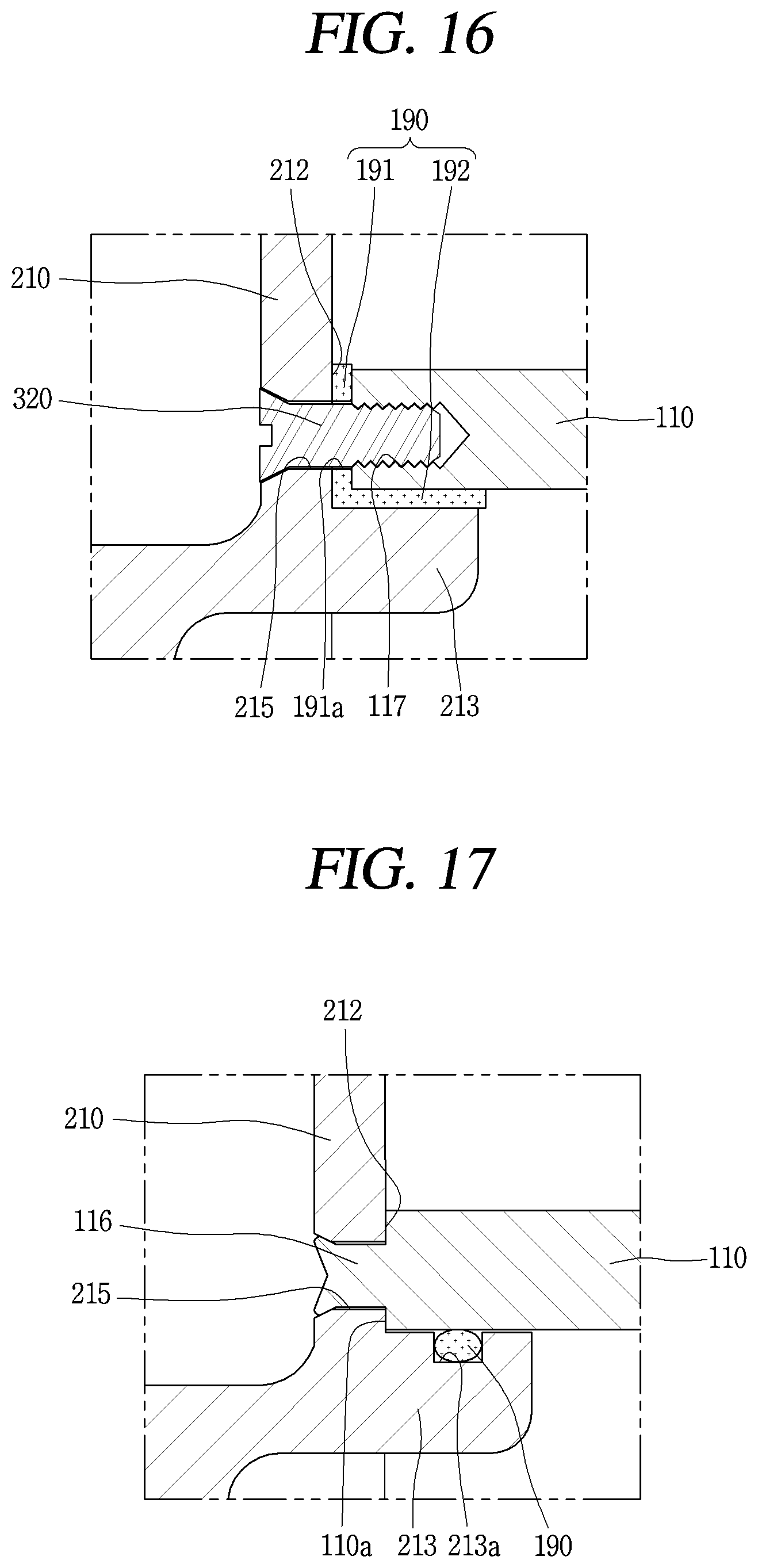
D00016

XML
uspto.report is an independent third-party trademark research tool that is not affiliated, endorsed, or sponsored by the United States Patent and Trademark Office (USPTO) or any other governmental organization. The information provided by uspto.report is based on publicly available data at the time of writing and is intended for informational purposes only.
While we strive to provide accurate and up-to-date information, we do not guarantee the accuracy, completeness, reliability, or suitability of the information displayed on this site. The use of this site is at your own risk. Any reliance you place on such information is therefore strictly at your own risk.
All official trademark data, including owner information, should be verified by visiting the official USPTO website at www.uspto.gov. This site is not intended to replace professional legal advice and should not be used as a substitute for consulting with a legal professional who is knowledgeable about trademark law.