Drilling Performance Optimization With Extremum Seeking
ZALLUHOGLU; Umut ; et al.
U.S. patent application number 16/523837 was filed with the patent office on 2020-02-06 for drilling performance optimization with extremum seeking. This patent application is currently assigned to HALLIBURTON ENERGY SERVICES, INC.. The applicant listed for this patent is HALLIBURTON ENERGY SERVICES, INC.. Invention is credited to Robert P. DARBE, Nazli DEMIRER, Julien MARCK, Umut ZALLUHOGLU.
| Application Number | 20200040720 16/523837 |
| Document ID | / |
| Family ID | 69228387 |
| Filed Date | 2020-02-06 |


| United States Patent Application | 20200040720 |
| Kind Code | A1 |
| ZALLUHOGLU; Umut ; et al. | February 6, 2020 |
DRILLING PERFORMANCE OPTIMIZATION WITH EXTREMUM SEEKING
Abstract
A drilling optimization method including perturbing one or more drilling control parameters with a periodic or a stochastic signal during a drilling process, estimating at least one drilling performance measure to optimize the drilling process based on the perturbed one or more drilling control parameters, perturbing the at least one drilling performance measure with a periodic or a stochastic perturbation source through demodulation, determine a next best estimate of the one or more drilling control parameters to optimize the at least one drilling performance measure, perturbing the next best estimate by a periodic or a stochastic perturbation source through modulation, and feeding the perturbation next best estimates of the one or more drilling control parameters back to the drilling process.
| Inventors: | ZALLUHOGLU; Umut; (Humble, TX) ; MARCK; Julien; (Houston, TX) ; DARBE; Robert P.; (Tomball, TX) ; DEMIRER; Nazli; (Houston, TX) | ||||||||||
| Applicant: |
|
||||||||||
|---|---|---|---|---|---|---|---|---|---|---|---|
| Assignee: | HALLIBURTON ENERGY SERVICES,
INC. Houston TX |
||||||||||
| Family ID: | 69228387 | ||||||||||
| Appl. No.: | 16/523837 | ||||||||||
| Filed: | July 26, 2019 |
Related U.S. Patent Documents
| Application Number | Filing Date | Patent Number | ||
|---|---|---|---|---|
| 62713009 | Aug 1, 2018 | |||
| Current U.S. Class: | 1/1 |
| Current CPC Class: | E21B 44/02 20130101; E21B 7/04 20130101; E21B 44/00 20130101 |
| International Class: | E21B 44/00 20060101 E21B044/00 |
Claims
1. A method comprising: perturbing a drilling control parameter with a periodic or a stochastic signal during a drilling process; estimating or calculating a drilling performance measure to optimize the drilling process based on the perturbation of the drilling control parameter; perturbing the drilling performance measure by multiplying the drilling performance measure with a periodic or a stochastic perturbation source through demodulation; determining a next best estimate of the drilling control parameter to optimize the drilling performance measure; perturbing the next best estimate by a periodic or a stochastic perturbation source through modulation; and feeding the perturbed next best estimate of the drilling control parameters to the drilling process.
2. The method of claim 1, further comprising feeding the drilling performance measure through a high-pass filter.
3. The method of claim 1, further comprising feeding the perturbed drilling performance measure through a low-pass filter.
4. The method of claim 1, wherein determining the next best estimate comprises integrating a gradient to calculate the next best estimate.
5. The method of claim 1, wherein feeding next best estimate to the drilling process includes adjusting the one or more drilling control parameters thus optimizing the selected at least one drilling performance measure.
6. The method of claim 1, drilling at least a portion of a wellbore based on the perturbed next best estimate.
7. The method of claim 1, wherein estimating, perturbing, determining, perturbing, and feeding the perturbed next best estimate are repeated until a gradient is less than a predetermined threshold.
8. The method of claim 7, wherein the predetermined threshold is zero.
9. A drilling system comprising: a drilling rig operable to form a wellbore in a subterranean formation, the drilling rig having one or more processors and a memory coupled therewith, the one or more processors operable to execute instructions stored on the memory that cause the cause the drilling system to: perturb a drilling control parameter with a periodic or a stochastic signal during a drilling process; estimate or calculating a drilling performance measure to optimize the drilling process based on the perturbation of the drilling control parameter; perturb the drilling performance measure by multiplying the drilling performance measure with a periodic or a stochastic perturbation source through demodulation; determine a next best estimate of the drilling control parameter to optimize the drilling performance measure; perturb the next best estimate by a periodic or a stochastic perturbation source through modulation; and feed the perturbed next best estimate of the drilling control parameters to the drilling process.
10. The drilling system of claim 9, further comprising feed the drilling performance measure through a high-pass filter.
11. The drilling system of claim 9, further comprising feed the perturbed drilling performance measure through a low-pass filter.
12. The drilling system of claim 9, wherein determine the next best estimate comprises integrate a gradient to calculate the next best estimate.
13. The drilling system of claim 9, wherein feed the next best estimate to the drilling process includes adjust the one or more drilling control parameters thus optimizing the selected at least one drilling performance measure.
14. The drilling system of claim 9, drill at least a portion of a wellbore based on the perturbed next best estimate.
15. The drilling system of claim 9, wherein estimate, perturb, determine, perturbing, and feed the perturbed next best estimate are repeated until a gradient is less than a predetermined threshold.
16. The drilling system of claim 15, wherein the predetermined threshold is zero.
17. A non-transitory computer-readable medium comprising executable instructions, which when executed by a processor, causes the processor to: perturb a drilling control parameter with a periodic or a stochastic signal during a drilling process; estimate or calculating a drilling performance measure to optimize the drilling process based on the perturbation of the drilling control parameter; perturb the drilling performance measure by multiplying the drilling performance measure with a periodic or a stochastic perturbation source through demodulation; determine a next best estimate of the drilling control parameter to optimize the drilling performance measure; perturb the next best estimate by a periodic or a stochastic perturbation source through modulation; and feed the perturbed next best estimate of the drilling control parameters to the drilling process.
18. The non-transitory computer-readable medium of claim 17, further comprising feed the drilling performance measure through a high-pass filter.
19. The non-transitory computer-readable medium of claim 17, further comprising feed the perturbed drilling performance measure through a low-pass filter.
20. The non-transitory computer-readable medium of claim 17, wherein estimate, perturb, determine, perturb, and feed the perturbed next best estimate are repeated until a gradient is less than a predetermined threshold.
Description
CROSS REFERENCE TO RELATED APPLICATIONS
[0001] This application claims the benefit of U.S. Provisional Application No. 62/713,009, filed Aug. 1, 2018, the contents of which are incorporated by reference herein in their entirety.
FIELD
[0002] The present technology is directed to a system and method for drilling within a subterranean formation. In particular, the present technology involves a system and method for drilling optimization within a subterranean formation.
BACKGROUND
[0003] In an effort to extract hydrocarbons from subterranean formation, drilling operations are undertaken to form a wellbore through desirable portions of the subterranean formation. Drilling operations are directed at the surface to control one or more parameters in an attempt to maximize drilling efficiency and accuracy. Controllable parameters can include rate of penetration (ROP), weight on bit (WOB), and rotations per minute (RPM) adjustable to achieve a particular set point for each individual control parameter.
BRIEF DESCRIPTION OF THE DRAWINGS
[0004] The embodiments herein may be better understood by referring to the following description in conjunction with the accompanying drawings in which like reference numerals indicate analogous, identical, or functionally similar elements. Understanding that these drawings depict only exemplary embodiments of the disclosure and are not therefore to be considered to be limiting of its scope, the principles herein are described and explained with additional specificity and detail through the use of the accompanying drawings in which:
[0005] FIG. 1 is a schematic diagram of a drilling optimization process according to the present disclosure;
[0006] FIG. 2 is a diagrammatic view of a drilling optimization system according to the present disclosure;
[0007] FIG. 3A is a model of an extremum seeking method having ROP maximized by controlling WOB and RPM according to the present disclosure;
[0008] FIG. 3B is a result of an extremum seeking method having ROP maximized by controlling WOB and RPM according to the present disclosure;
[0009] FIG. 4 is a flow chart of a drilling optimization method according to the present disclosure; and
[0010] FIG. 5 is a diagram of a computer device that can implement various systems and methods discussed herein.
DETAILED DESCRIPTION
[0011] Various embodiments of the disclosure are discussed in detail below. While specific implementations are discussed, it should be understood that this is done for illustration purposes only. A person skilled in the relevant art will recognize that other components and configurations may be used without parting from the spirit and scope of the disclosure. Additional features and advantages of the disclosure will be set forth in the description which follows, and in part will be obvious from the description, or can be learned by practice of the herein disclosed principles. The features and advantages of the disclosure can be realized and obtained by means of the instruments and combinations particularly pointed out in the appended claims. These and other features of the disclosure will become more fully apparent from the following description and appended claims, or can be learned by the practice of the principles set forth herein.
[0012] The present disclosure is drawn to a new method for optimizing a drilling operation within a subterranean formation. The drilling optimization can target one or more drilling performance measures (for example, ROP, mechanical specific energy (MSE), torsional specific energy (TSE), or any combination thereof in a cost function) and can include two main processes occurring at different time scales: (i) a control parameter (for example, weight on bit (WOB), torque on bit (TOB), revolutions per minute (RPM), flow rate, choke, block height speed, draw-works speed, ROP, etc.) estimation process and (ii) a gradient estimation process. The control parameter estimation process is performed by an integrator and the gradient estimation process handled by modulation and demodulation of a feedback signal with a perturbation source. The perturbation frequency can control the separation between the two time scales.
[0013] The present disclosure includes methods and apparatuses for a drilling optimization system during subterranean formation drilling processes. The drilling optimization method, apparatus and related system can be implemented on land-based and/or sea-based drilling operations. While generally described and shown with respect to a land-based operation, the present disclosure can be similarly implemented in sea-based (e.g. off-shore) operations. In offshore applications, block height speed control process can be altered to include heave compensation.
[0014] The present disclosure targets optimization of a drilling performance measure (e.g., ROP, MSE, TSE, or any combination thereof). The present disclosure first estimates the drilling performance for a given set of control parameters then evaluates how to drive the input (e.g. control) parameters toward the extremum of the cost function, if not yet reached.
[0015] The method can include perturbing one or more control parameters with a periodic or stochastic signal during a drilling process. The perturbation of the one or more control parameter can allow control either automatically or manually of drilling system actuators. The method can calculate and/or estimate at least one drilling performance measurement during the drilling operation to be optimized. The drilling performance measure can be fed through a function performing a high-pass filter effect to eliminate the direct current (DC) component of the signal. The drilling performance measure can be perturbed (for example, multiplied) by a periodic or stochastic perturbation source through demodulation (for example, at substantially the same frequency as the perturbation with respect to the one or more control parameters). The perturbed (and filtered) signal can be fed through a function performing a low-pass filter effect. The method can integrate the gradient to calculate the next best estimate of the controlled parameters to optimize the drilling performance measure. The estimate can be perturbed by a periodic or stochastic perturbation source through modulation (for example, at substantially the same frequency as the demodulation of the drilling performance measure). The perturbed estimate of control parameters can be fed back to the drilling process, thus adjusting one or more drilling process parameter to optimize drilling performance. The method can be repeated with one or more control parameters and one or more drilling performance measures continuously to maintain optimized drilling performance.
[0016] The drilling process can pause (for example, to make pipe connections), thus allowing the optimum control parameter settings to be stored on a memory. Upon resuming of drilling, the control parameters can be initialized at their optimized settings.
[0017] The optimized control parameter settings throughout the entire drilling process can be stored in a non-volatile memory for at least one of the following purposes: (i) post-job analysis (ii) future well design and/or (iii) having the option to go back (e.g. revert) to any previous control parameter setting.
[0018] FIG. 1 illustrates an optimization-while-drilling (OWD) process according to at least one instance of the present disclosure. A drilling process 100 can include one or more drilling tools 11 and related equipment disposed on a surface 102 (or a boat/platform in sea based-operations). One or more drilling tools 11 can be coupled with the distal end 12 of a drill string 10. A drill bit 16 can be disposed at the distal end 12 of the drill string 10 and be operable to form a wellbore 14 in a subterranean formation 50. The wellbore 14 can have one or more vertical, curved, and/or horizontal portions extending through one or more portions of the subterranean formation 50. In at least one instance, the wellbore 14 is formed through one or more pay zone portions of the subterranean formation 50. The one or more pay zones having a more desirable hydrocarbon production.
[0019] The drill string 10 can be operable to optimize drilling performance during drilling processes either locally or through the surface or through a remotely located drill optimization control system 18. The drill string 10 or related drilling optimization control system 18 can be operable to be controlled locally on the drill string 10 by one or more drilling tools 11, controlled on the surface 102, and/or controlled remotely to adjust one or more drilling parameters including, but not limited to, control parameters and drilling performance measures. While FIG. 1 shows the drill optimization control system 18 disposed at the surface 102, it is within the scope of this disclosure to implement the drilling optimization control system 18 locally on the drill string 10 or remotely off-site. In at least one instance, the drill optimization control system 18 can include, but not limited to, one or more processors, random access memory (RAM), and/or storage medium. One or more control parameters of the drill string 10 can be adjusted during drilling operations to improve one or more drilling performance measures.
[0020] The drill string 10 can optimize a drilling performance measure including, but not limited to ROP, MSE, TSE, or any combination thereof utilizing one or more control parameters including, but not limited to, Block Height Speed, WOB, TOB, RPM, flow rate, and the like. The drill string 10 can adjust one or more control parameters using perturbation to improve one or more drilling performance measures.
[0021] FIG. 2 is a diagrammatic view representing a drilling performance optimization process according to at least one instance of the present disclosure. The dashed elements shown in FIG. 2 represent optional processes the can be implemented to improve the control performance.
[0022] The drilling process 202 can have an input vector, u, representing at least one drilling control parameter including, but not limited to, Block Height Speed, WOB, TOB, RPM, flow rate, and the like, and the output vector y represents at least one drilling performance measure including, but not limited to, ROP, MSE, TSE, and combinations thereof.
[0023] As the perturbation source 204, a periodic signal, such as a sinusoidal can be used, Asin(wt), where w is the perturbation frequency and A is the perturbation amplitude. A high w is desirable to get better estimation of the gradient and to have smaller influence from perturbing high order dynamics of the drilling process. The smaller A is, the smaller the residual error can be obtained at the extremum; however, it also brings the risk of getting caught in a local extremum.
[0024] In other instances, a stochastic signal can be used as the perturbation source 204.
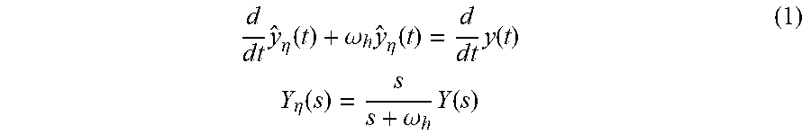
[0025] In some instances, a high-pass filtering effect 206 (for example, wash out filter) can be represented by f.sub.HPF(u). The high-pass filtering effect can remove the DC gain from the signal, y. In at least one instance, a simple high-pass filter such as:
d d t y ^ .eta. ( t ) + .omega. h y ^ .eta. ( t ) = d d t y ( t ) Y .eta. ( s ) = s s + .omega. h Y ( s ) ( 1 ) ##EQU00001##
[0026] can be used, where, .omega..sub.h, is the cut-off frequency of the high-pass filter. To achieve optimum DC gain elimination performance .omega..sub.h should be selected smaller than .omega..
[0027] In some instances, a low-pass filter effect 208 can be represented by f.sub.LPF(y.sub..eta.), The low-pass filter effect 208 can better estimate the gradient, .xi.. In at least one instance, a simple low-pass filter such as:
d d t .xi. ( t ) + .omega. l .xi. ( t ) = .omega. l y ^ .eta. ( t ) E ( s ) = .omega. l s + .omega. l Y .eta. ( s ) ( 2 ) ##EQU00002##
can be used where, .omega..sub.1, is the cut-off frequency of the low-pass filter.
[0028] The integration process 210, f.sub.1(.xi.) with a gain vector, K, can be used to control the speed of convergence. A form of the integrator is shown below:
u ^ = ( t ) = K .intg. 0 .infin. .xi. ( t ) d t U ^ ( s ) = K s E ( s ) ( 3 ) ##EQU00003##
The resulting best estimate for the controller parameter vector, {circumflex over (.mu.)}, can be bounded at this stage by using an integrator with upper and lower bounds. These bounds can be induced by the operational limits of the drilling rig and/or the directional tool implemented for the particular drilling operation. As each drilling rig, drilling tool, and/or directional tool can have varying operational limits, the bounds can vary based on tool selection and/or implementation.
[0029] If there are multiple inputs to the drilling process, each input can be perturbed with different amplitude and rate based on numerical properties of the control parameters and physical capabilities of the actuators.
[0030] FIG. 3A is an illustrative example of the control method. To simulate a drilling process, a well-established relation between WOB, RPM, and ROP can be used, where drilling dysfunctions (founders and limiters) limits ROP. FIG. 3B represents the model and the result of extremum seeking method, where ROP is maximized by controlling WOB and RPM.
[0031] With respect to FIG. 3A, the relationships between ROP, RPM, and WOB can be visualized along with the founders and limiters including hole cleaning, hole instability, stickslip, whirl, directional tendency, and/or weight transfer to bit. As can be appreciated in FIG. 3A, increasing ROP can substantially linearly increase WOB/RPM, and thus the founders and limiters can be experienced.
[0032] As can be appreciated in FIG. 3B, ROP asymptotically approaches a maximum by controlling the WOB and RPM over time. In this illustrative instance, one or more control parameters (e.g. WOB and/or RPM) can be implemented with a perturbation source with a periodic or stochastic signal prior to beginning the drilling process. At least one drilling performance measurement that is to be optimized (e.g. ROP) can be calculated and/or estimated. The drilling performance measurement can then be perturbed by a periodic or stochastic perturbation source through demodulation at substantially the same frequency as the perturbation source implemented with respect to the one or more control parameters. A gradient can be integrated to calculate a next best estimate of the one or more controlled parameters to optimize the drilling performance measurement. The next best estimate of the one or more controlled parameters can be perturbed by a periodic through modulation, and the perturbed next best estimate can be then be fed and/or implemented with the drilling process. The process can be repetitively implemented until the gradient is less than a predetermined threshold (e.g. zero). The gradient can asymptotically approach zero, as illustrated by FIG. 3B, with the ROP iteratively changing (oscillating) as the control parameters (RPM/WOB) are adjusted and the ROP approaches a hypothetical maximum.
[0033] Referring to FIG. 4, a flowchart is presented in accordance with an example method. The example method 400 is provided by way of example, as there is a variety of ways to carry out the method 400. Each block shown in FIG. 4 represents one or more processes, methods, or subroutines carried out in the example method 400. Furthermore, the illustrated order of blocks is illustrative only and the order of the blocks can change according to the present disclosure. Additional blocks may be added or fewer blocks can be utilized, without deviating from the present disclosure. The example method 400 can begin at block 402.
[0034] At block 402, one or more control parameters can be perturbed with a periodic or stochastic signal prior to entering the drilling process. The method can proceed to block 404.
[0035] At block 404, at least one drilling performance measure can be calculated and/or estimated to be optimized during the drilling process. The method 400 can calculate and/or estimate the drilling performance measure based on the one or more control parameter perturbations from block 402. The method 400 can optionally proceed to block 406 or block 408.
[0036] At block 406, the at least one drilling performance measure can be fed through a high-pass filter to kill the DC component of the signal. The method 400 can proceed to block 408.
[0037] At block 408, the at least one drilling performance measure can be perturbed (multiplied) by a periodic or stochastic perturbation source through demodulation. In at least one instance, the perturbation occurs at the same frequency with the perturbation in block 402. The method 400 can optionally proceed to block 410 or block 412.
[0038] At block 410, the perturbed signal can be fed through a low-pass filter effect. The perturbed signal can have been previously filtered in block 406. The method 400 can proceed to block 412.
[0039] At block 412, the gradient can be integrated to calculate the next best estimate of the one or more controlled parameters to optimize at least one drilling performance measure. The method 400 can proceed to block 414.
[0040] At block 414, the estimate calculated in block 412 can be perturbed by a periodic or stochastic perturbation source through modulation. In at least one instance, the perturbation occurs at the same frequency with the perturbation in block 406. The method 400 can proceed to block 416.
[0041] At block 416, the perturbed estimates of the one or more control parameters can be fed back to the drilling process. The perturbed estimates of the one or more control parameters can adjust the drilling process and drilling operation to optimize the selected at least one drilling performance measure. The method 400 can proceed to block 418.
[0042] At block 418, blocks 404-418 can be repeated, as necessary, until the gradient is less than a predetermined threshold. In at least one instance, the predetermined threshold is approximately zero. The repetition of blocks 404-418 can further refine the optimization of the drilling process and drilling operation, further improving optimization of the selected at least one drilling performance measure.
[0043] Referring to FIG. 5, a detailed description of an example computer device 500 is provided that can operably implement various systems and methods discussed herein. The computer device can be applicable to the drilling process 100 and/or one or more drilling tools 11 and other computing or network devices. It will be appreciated that specific implementations of these devices can be of differing possible specific computing architectures, not all of which are specifically discussed herein but will be understood by those of ordinary skill in the art.
[0044] The computer device 500 can be a computing system capable of executing a computer program product to execute a computer process. Data and program files can be input to the computer device 500, which reads the files and executes the programs therein. Some of the elements of the computer device 500 are shown in FIG. 5, including one or more hardware processors 502, one or more data storage devices 504, one or more memory devices 508, and/or one or more ports 508-510. Additionally, other elements that will be recognized by those skilled in the art can be included in the computer device 500 but are not explicitly depicted in FIG. 5 or discussed further herein. Various elements of the computer device 500 can communicate with one another by way of one or more communication buses, point-to-point communication paths, or other communication means not explicitly depicted in FIG. 5.
[0045] The processor 502 can include, for example, a central processing unit (CPU), a microprocessor, a microcontroller, a digital signal processor (DSP), and/or one or more internal levels of cache. There can be one or more processors 502, such that the processor 502 comprises a single central-processing unit, or a plurality of processing units capable of executing instructions and performing operations in parallel with each other, commonly referred to as a parallel processing environment.
[0046] The computer device 500 can be a conventional computer, a distributed computer, or any other type of computer, such as one or more external computers made available via a cloud computing architecture. The presently described technology is optionally implemented in software stored on the data stored device(s) 504, stored on the memory device(s) 506, and/or communicated via one or more of the ports 508-510, thereby transforming the computer device 500 in FIG. 5 to a special purpose machine for implementing the operations described herein. Examples of the computer device 500 include personal computers, terminals, workstations, mobile phones, tablets, laptops, personal computers, multimedia consoles, gaming consoles, set top boxes, and the like.
[0047] The one or more data storage devices 504 can include any non-volatile data storage device capable of storing data generated or employed within the computer device 500, such as computer executable instructions for performing a computer process, which can include instructions of both application programs and an operating system (OS) that manages the various components of the computer device 500. The data storage devices 504 can include, without limitation, magnetic disk drives, optical disk drives, solid state drives (SSDs), flash drives, and the like. The data storage devices 504 can include removable data storage media, non-removable data storage media, and/or external storage devices made available via a wired or wireless network architecture with such computer program products, including one or more database management products, web server products, application server products, and/or other additional software components. Examples of removable data storage media include Compact Disc Read-Only Memory (CD-ROM), Digital Versatile Disc Read-Only Memory (DVD-ROM), magneto-optical disks, flash drives, and the like. Examples of non-removable data storage media include internal magnetic hard disks, SSDs, and the like. The one or more memory devices 506 can include volatile memory (e.g., dynamic random access memory (DRAM), static random access memory (SRAM), etc.) and/or non-volatile memory (e.g., read-only memory (ROM), flash memory, etc.).
[0048] Computer program products containing mechanisms to effectuate the systems and methods in accordance with the presently described technology can reside in the data storage devices 504 and/or the memory devices 506, which can be referred to as machine-readable media. It will be appreciated that machine-readable media can include any tangible non-transitory medium that is capable of storing or encoding instructions to perform any one or more of the operations of the present disclosure for execution by a machine or that is capable of storing or encoding data structures and/or modules utilized by or associated with such instructions. Machine-readable media can include a single medium or multiple media (e.g., a centralized or distributed database, and/or associated caches and servers) that store the one or more executable instructions or data structures.
[0049] In some implementations, the computer device 500 includes one or more ports, such as an input/output (I/O) port 508 and a communication port 510, for communicating with other computing, network, or vehicle devices. It will be appreciated that the ports 508-510 can be combined or separate and that more or fewer ports can be included in the computer device 500.
[0050] The I/O port 508 can be connected to an I/O device, or other device, by which information is input to or output from the computer device 500. Such I/O devices can include, without limitation, one or more input devices, output devices, and/or environment transducer devices.
[0051] In one implementation, the input devices convert a human-generated signal, such as, human voice, physical movement, physical touch or pressure, and/or the like, into electrical signals as input data into the computer device 500 via the I/O port 508. Similarly, the output devices can convert electrical signals received from computer device 500 via the I/O port 508 into signals that can be sensed as output by a human, such as sound, light, and/or touch. The input device can be an alphanumeric input device, including alphanumeric and other keys for communicating information and/or command selections to the processor 502 via the I/O port 1608. The input device can be another type of user input device including, but not limited to: direction and selection control devices, such as a mouse, a trackball, cursor direction keys, a joystick, and/or a wheel; one or more sensors, such as a camera, a microphone, a positional sensor, an orientation sensor, a gravitational sensor, an inertial sensor, and/or an accelerometer; and/or a touch-sensitive display screen ("touchscreen"). The output devices can include, without limitation, a display, a touchscreen, a speaker, a tactile and/or haptic output device, and/or the like. In some implementations, the input device and the output device can be the same device, for example, in the case of a touchscreen.
[0052] The environment transducer devices convert one form of energy or signal into another for input into or output from the computer device 500 via the I/O port 508. For example, an electrical signal generated within the computer device 500 can be converted to another type of signal, and/or vice-versa. In one implementation, the environment transducer devices sense characteristics or aspects of an environment local to or remote from the computer device 500, such as, light, sound, temperature, pressure, magnetic field, electric field, chemical properties, physical movement, orientation, acceleration, gravity, and/or the like. Further, the environment transducer devices can generate signals to impose some effect on the environment either local to or remote from the example computer device 500, such as, physical movement of some object (e.g., a mechanical actuator), heating or cooling of a substance, adding a chemical substance, and/or the like.
[0053] In one implementation, a communication port 510 is connected to a network by way of which the computer device 500 can receive network data useful in executing the methods and systems set out herein as well as transmitting information and network configuration changes determined thereby. Stated differently, the communication port 510 connects the computer device 500 to one or more communication interface devices configured to transmit and/or receive information between the computer device 500 and other devices by way of one or more wired or wireless communication networks or connections. Examples of such networks or connections include, without limitation, Universal Serial Bus (USB), Ethernet, Wi-Fi, Bluetooth.RTM., Near Field Communication (NFC), Long-Term Evolution (LTE), and so on. One or more such communication interface devices can be utilized via the communication port 1310 to communicate one or more other machines, either directly over a point-to-point communication path, over a wide area network (WAN) (e.g., the Internet), over a local area network (LAN), over a cellular (e.g., third generation (3G) or fourth generation (4G)) network, or over another communication means. Further, the communication port 510 can communicate with an antenna or other link for electromagnetic signal transmission and/or reception.
[0054] In an example implementation, health data, air filtration data, and software and other modules and services can be embodied by instructions stored on the data storage devices 504 and/or the memory devices 506 and executed by the processor 502. The computer device 500 can be integrated with or otherwise form part of the system for dynamic light adjustments.
[0055] The system set forth in FIG. 5 is but one possible example of a computer system that can employ or be configured in accordance with aspects of the present disclosure. It will be appreciated that other non-transitory tangible computer-readable storage media storing computer-executable instructions for implementing the presently disclosed technology on a computing system can be utilized.
[0056] In the present disclosure, the methods disclosed can be implemented as sets of instructions or software readable by a device (e.g., the computer device 500). Further, it is understood that the specific order or hierarchy of steps in the methods disclosed are instances of example approaches. Based upon design preferences, it is understood that the specific order or hierarchy of steps in the method can be rearranged while remaining within the disclosed subject matter. The accompanying method claims present elements of the various steps in a sample order, and are not necessarily meant to be limited to the specific order or hierarchy presented.
[0057] The embodiments shown and described above are only examples. Even though numerous characteristics and advantages of the present technology have been set forth in the foregoing description, together with details of the structure and function of the present disclosure, the disclosure is illustrative only, and changes may be made in the detail, especially in matters of shape, size and arrangement of the parts within the principles of the present disclosure to the full extent indicated by the broad general meaning of the terms used in the attached claims. It will therefore be appreciated that the embodiments described above may be modified within the scope of the appended claims.
Statement Bank
[0058] Statement 1: A method comprising: perturbing a drilling control parameter with a periodic or a stochastic signal during a drilling process; estimating or calculating a drilling performance measure to optimize the drilling process based on the perturbation of the drilling control parameter; perturbing the drilling performance measure by multiplying the drilling performance measure with a periodic or a stochastic perturbation source through demodulation; determining a next best estimate of the drilling control parameter to optimize the drilling performance measure; perturbing the next best estimate by a periodic or a stochastic perturbation source through modulation; and feeding the perturbed next best estimate of the drilling control parameters to the drilling process.
[0059] Statement 2: The method of Statement 1, further comprising feeding the drilling performance measure through a high-pass filter.
[0060] Statement 3: The method of Statement 1 or Statement 2, further comprising feeding the perturbed drilling performance measure through a low-pass filter.
[0061] Statement 4: The method of any one of Statements 1-3, wherein determining the next best estimate comprises integrating a gradient to calculate the next best estimate.
[0062] Statement 5: The method of any one of Statements 1-4, wherein feeding next best estimate to the drilling process includes adjusting the one or more drilling control parameters thus optimizing the selected at least one drilling performance measure.
[0063] Statement 6: The method of any one of Statements 1-5, drilling at least a portion of a wellbore based on the perturbed next best estimate.
[0064] Statement 7: The method of any one of Statements 1-6, wherein estimating, perturbing, determining, perturbing, and feeding the perturbed next best estimate are repeated until a gradient is less than a predetermined threshold.
[0065] Statement 8: The method of any one of Statements 1-7, wherein the predetermined threshold is zero.
[0066] Statement 9: A drilling system comprising: a drilling rig operable to form a wellbore in a subterranean formation, the drilling rig having one or more processors and a memory coupled therewith, the one or more processors operable to execute instructions stored on the memory that cause the cause the drilling system to: perturb a drilling control parameter with a periodic or a stochastic signal during a drilling process; estimate or calculating a drilling performance measure to optimize the drilling process based on the perturbation of the drilling control parameter; perturb the drilling performance measure by multiplying the drilling performance measure with a periodic or a stochastic perturbation source through demodulation; determine a next best estimate of the drilling control parameter to optimize the drilling performance measure; perturb the next best estimate by a periodic or a stochastic perturbation source through modulation; and feed the perturbed next best estimate of the drilling control parameters to the drilling process.
[0067] Statement 10: The drilling system of Statement 9, further comprising feed the drilling performance measure through a high-pass filter.
[0068] Statement 11: The drilling system of Statement 9 or Statement 10, further comprising feed the perturbed drilling performance measure through a low-pass filter.
[0069] Statement 12: The drilling system of any one of Statements 9-11, wherein determine the next best estimate comprises integrate a gradient to calculate the next best estimate.
[0070] Statement 13: The drilling system of any one of Statements 9-12, wherein feed the next best estimate to the drilling process includes adjust the one or more drilling control parameters thus optimizing the selected at least one drilling performance measure.
[0071] Statement 14: The drilling system of any one of Statements 9-13, drill at least a portion of a wellbore based on the perturbed next best estimate.
[0072] Statement 15: The drilling system of any one of Statements 9-14, wherein estimate, perturb, determine, perturbing, and feed the perturbed next best estimate are repeated until a gradient is less than a predetermined threshold.
[0073] Statement 16: The drilling system of any one of Statements 9-15, wherein the predetermined threshold is zero.
[0074] Statement 17: A non-transitory computer-readable medium comprising executable instructions, which when executed by a processor, causes the processor to: perturb a drilling control parameter with a periodic or a stochastic signal during a drilling process; estimate or calculating a drilling performance measure to optimize the drilling process based on the perturbation of the drilling control parameter; perturb the drilling performance measure by multiplying the drilling performance measure with a periodic or a stochastic perturbation source through demodulation; determine a next best estimate of the drilling control parameter to optimize the drilling performance measure; perturb the next best estimate by a periodic or a stochastic perturbation source through modulation; and feed the perturbed next best estimate of the drilling control parameters to the drilling process.
[0075] Statement 18: The non-transitory computer-readable medium of Statement 17, further comprising feed the drilling performance measure through a high-pass filter.
[0076] Statement 19: The non-transitory computer-readable medium of Statement 17 or Statement 18, further comprising feed the perturbed drilling performance measure through a low-pass filter.
[0077] Statement 20: The non-transitory computer-readable medium of any one of Statements 17-19, wherein estimate, perturb, determine, perturb, and feed the perturbed next best estimate are repeated until a gradient is less than a predetermined threshold.
* * * * *
D00000
D00001
D00002
D00003
D00004
D00005
XML
uspto.report is an independent third-party trademark research tool that is not affiliated, endorsed, or sponsored by the United States Patent and Trademark Office (USPTO) or any other governmental organization. The information provided by uspto.report is based on publicly available data at the time of writing and is intended for informational purposes only.
While we strive to provide accurate and up-to-date information, we do not guarantee the accuracy, completeness, reliability, or suitability of the information displayed on this site. The use of this site is at your own risk. Any reliance you place on such information is therefore strictly at your own risk.
All official trademark data, including owner information, should be verified by visiting the official USPTO website at www.uspto.gov. This site is not intended to replace professional legal advice and should not be used as a substitute for consulting with a legal professional who is knowledgeable about trademark law.