Isolation Device And Assembly For A Hydraulic Fracturing Process
Coon; Robert ; et al.
U.S. patent application number 16/528152 was filed with the patent office on 2020-02-06 for isolation device and assembly for a hydraulic fracturing process. The applicant listed for this patent is PetroFrac Oil Tools. Invention is credited to Robert Coon, Roddie R. Smith.
| Application Number | 20200040713 16/528152 |
| Document ID | / |
| Family ID | 69227511 |
| Filed Date | 2020-02-06 |
| United States Patent Application | 20200040713 |
| Kind Code | A1 |
| Coon; Robert ; et al. | February 6, 2020 |
ISOLATION DEVICE AND ASSEMBLY FOR A HYDRAULIC FRACTURING PROCESS
Abstract
An isolation device and assembly for isolating a production casing in a hydraulic fracturing process includes a hemispheric or tapered first end and a cylindrical second end. The isolation device is constructed of a dissolvable material. The hemispheric or tapered first end seats in a plug to effect the isolation.
| Inventors: | Coon; Robert; (Missouri City, TX) ; Smith; Roddie R.; (Katy, TX) | ||||||||||
| Applicant: |
|
||||||||||
|---|---|---|---|---|---|---|---|---|---|---|---|
| Family ID: | 69227511 | ||||||||||
| Appl. No.: | 16/528152 | ||||||||||
| Filed: | July 31, 2019 |
Related U.S. Patent Documents
| Application Number | Filing Date | Patent Number | ||
|---|---|---|---|---|
| 62713318 | Aug 1, 2018 | |||
| Current U.S. Class: | 1/1 |
| Current CPC Class: | E21B 43/26 20130101; E21B 43/119 20130101; E21B 33/1204 20130101; E21B 2200/08 20200501 |
| International Class: | E21B 43/119 20060101 E21B043/119; E21B 43/26 20060101 E21B043/26 |
Claims
1. An isolation device for a hydraulic fracturing plug, comprising: a first end that is configured to seat in the hydraulic fracturing plug; and a second end that is cylindrical, wherein the isolation device comprises a dissolvable material.
2. The isolation device of claim 1, wherein the isolation device is a monolithic piece.
3. The isolation device of claim 1, wherein the isolation device is hollow.
4. The isolation device of claim 1, wherein the first end is hemispherical.
5. The isolation device of claim 4, wherein the first end comprises a hemispherical wall that is defined as a portion between a hemisphere inner radius and a hemisphere outer radius, the hemisphere inner radius and the hemisphere outer radius defined from a central point of origin.
6. The isolation device of claim 5, wherein the hemispherical wall has a uniform thickness.
7. The isolation device of claim 5, wherein the hemispherical wall has a variable thickness.
8. The isolation device of claim 1, wherein the second end is hollow.
9. The isolation device of claim 4, wherein the first end includes a hemisphere outer radius, and the second end comprises a length that is greater than the hemisphere outer radius.
10. The isolation device of claim 1, wherein the isolation device includes a length that is greater than an internal diameter of a production casing, the production casing positioned in a wellbore and configured to receive the hydraulic fracturing plug.
11. The isolation device of claim 1, wherein the first end is tapered.
12. An isolation device for a hydraulic fracturing process, comprising: a hemispheric or tapered first end; and a cylindrical second end, wherein the isolation device is hollow and comprises a dissolvable material.
13. The isolation device of claim 12, wherein the dissolvable material is a polyglycolic acid.
14. The isolation device of claim 12, wherein the dissolvable material is a magnesium aluminum alloy.
15. The isolation device of claim 12, wherein the dissolvable material is an aluminum alloy.
16. A plug assembly for a hydraulic fracturing process, comprising: a plug that is configured to seat inside a production casing of a wellbore; an isolation device that is configured to isolate the production casing below the plug, wherein the isolation device comprises a first end and a cylindrical second end, the first end configured to seat the isolation device in the plug, and the isolation device constructed of a dissolvable material.
17. The plug assembly of claim 16, wherein the isolation device is hollow.
18. The plug assembly of claim 16, wherein the isolation device includes a length that is greater than an internal diameter of the production casing.
19. The plug assembly of claim 16, wherein the first end is hemispherical.
20. The plug assembly of claim 16, wherein the first end is tapered.
Description
CROSS-REFERENCE TO RELATED APPLICATIONS
[0001] This application claims the benefit of U.S. Provisional Patent Application having Ser. No. 62/713,318 which was filed Aug. 1, 2018. The aforementioned patent application is hereby incorporated by reference in its entirety into the present application to the extent consistent with the present application.
BACKGROUND
[0002] Hydraulic fracturing processes, or "fracing" as the processes are commonly known, are well stimulation techniques that are intended to increase the production of oil and gas. Simply stated, fracing involves drilling a wellbore into an earthen formation with low permeability and fracturing the earthen formation in several areas to help release and recover hydrocarbons from the earthen formation.
[0003] Fracing usually starts by establishing a well. A wellbore may be drilled into an earthen formation by a drill bit connected to a drill pipe. Once the desired depth is reached, the drill bit and the drill pipe are removed from the wellbore, and production casing is inserted into the full length of the wellbore. The production casing diameter is less than the diameter of the wellbore, which leaves an open area between the outer wall of the production casing and the wellbore. Therefore, to secure the wellbore and to later direct the released hydrocarbons to the surface, cement is pumped down the production casing to the bottom of the wellbore and forced back up and around the production casing to fill and set the open area. A temporary wellhead is installed at the surface, therefore establishing the well.
[0004] A "plug and perf" operation may be used to complete the well. A plug and a perforation ("perf") gun may be sent into the wellbore via a wireline or coiled tubing. Once a desired depth is reached, the plug is seated within the production casing. The perforation gun is fired above the plug, thereby perforating the production casing and the surrounding formation. The perforation gun is removed, and a frac ball is dropped into the perforated casing where it is seated in a reciprocal sleeve of the plug, thereby isolating the perforated casing from the completion below. Once the completion below is isolated, hydraulic fluid is sent down the production casing and into the perforations, which fractures the earthen formation and releases hydrocarbons into the wellbore. After treatment of the fractured area is complete, another plug with a perforation gun may be inserted into the wellbore at a location above the previous plug and performations in the wellbore. The plug and perf operation may be repeated in several stages. Once the plug and perf operation is complete, the frac balls and plugs may be removed by drilling them out, and the hydrocarbons may be allowed to flow through the wellbore to the surface.
[0005] The frac balls, the seats of the plugs, and/or the entire body of the plugs may be fabricated of a dissolvable material to expedite the plug and perf process. The dissolvable material disintegrates in the presence of wellbore fluids, therefore eliminating the need to drill out the frac balls and plugs. The dissolvable frac balls and plugs reduce completion time, lower costs and risks associated with drilling out the balls and plugs and leave behind an unobstructed wellbore for the recovery of hydrocarbons.
[0006] However, the frac balls that are used to isolate the wellbore may have a larger volume of dissolvable material than the plug, which results in a longer time for the balls and plugs to dissolve. The longer dissolving time slows down the plug and perf completion time. Therefore, there is a need for an improved isolation device for a hydraulic fracturing process that reduces completion time and avoids the costs and risks associated with drilling out balls and plugs during completion.
SUMMARY
[0007] In one embodiment of the invention, an isolation device for a hydraulic fracturing plug may include a first end that is configured to seat in the hydraulic fracturing plug and a second end that is cylindrical. The isolation device may be constructed of a dissolvable material.
[0008] In another embodiment of the invention, an isolation device for a hydraulic fracturing process may include a hemispheric or tapered first end and a cylindrical second end. The isolation device may be hollow and may be constructed of a dissolvable material.
[0009] In another embodiment of the invention, a plug assembly for a hydraulic fracturing process may include a plug that is configured to seat inside a production casing of a wellbore and an isolation device that is configured to be seated in the plug and configured to isolate the production casing below of the plug. The isolation device may include a first end and a cylindrical second end, and the first end may be configured to seat the isolation device in the plug.
BRIEF DESCRIPTION OF THE DRAWINGS
[0010] The present disclosure is best understood from the following detailed description when read with the accompanying Figures. It is emphasized that, in accordance with the standard practice in the industry, various features are not drawn to scale. In fact, the dimensions of the various features may be arbitrarily increased or reduced for clarity of discussion.
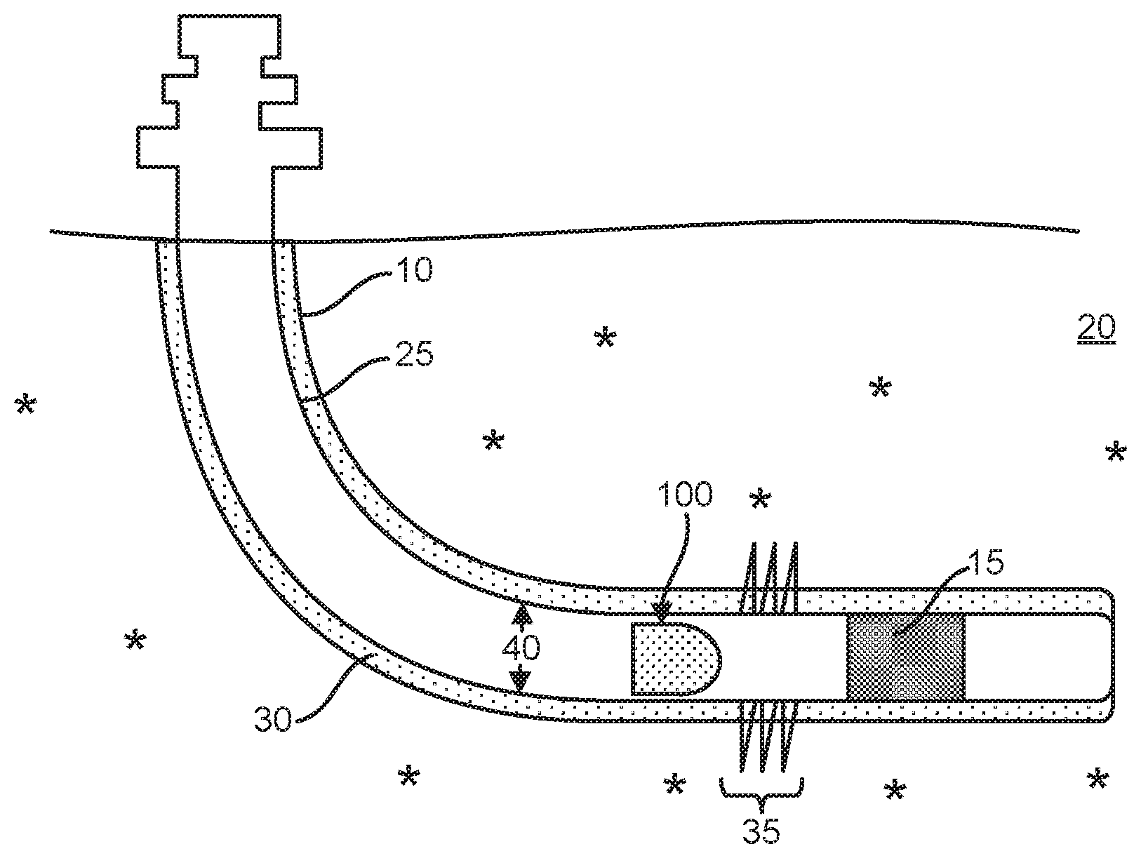
[0011] FIG. 1 is a cross-sectional view of a wellbore with a plug and an isolation device, according to one or more embodiments disclosed herein.
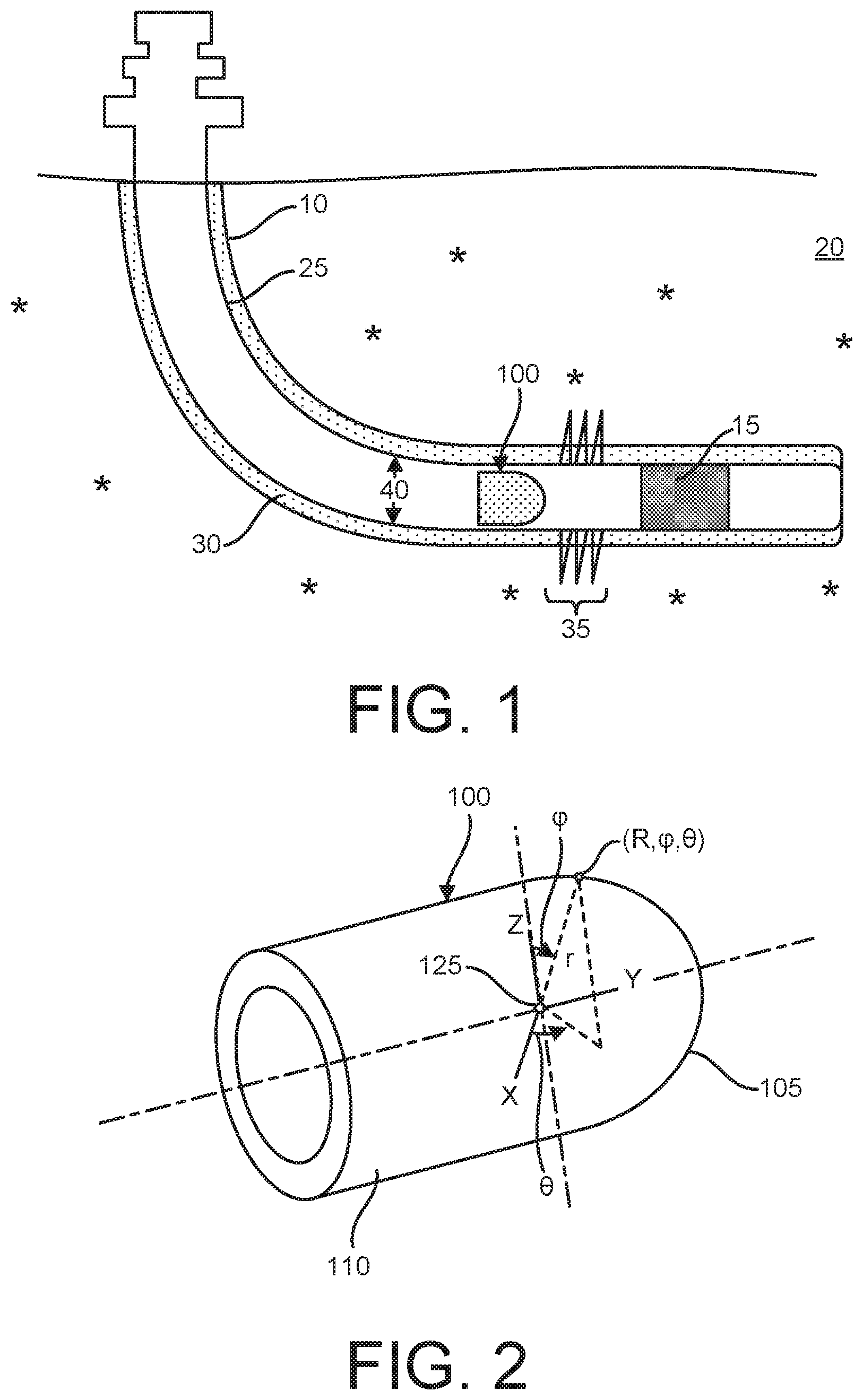
[0012] FIG. 2 is an isometric view of the isolation device, according to one or more embodiments disclosed herein.
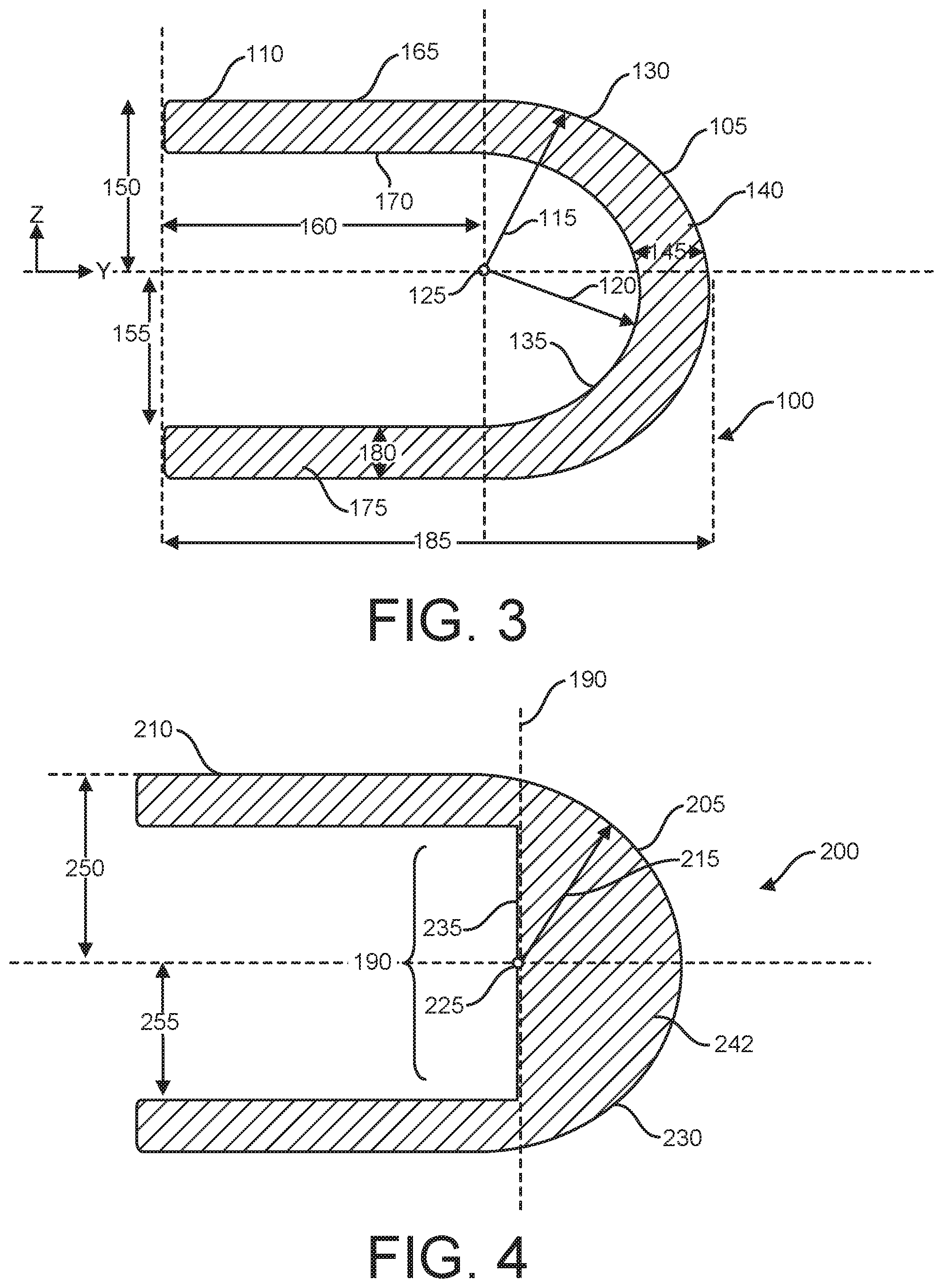
[0013] FIG. 3 is a cross section of a side view of an isolation device, according to one or more embodiments disclosed herein.
[0014] FIG. 4 is a cross section of a side view of another isolation device, according to one or more embodiments disclosed herein.
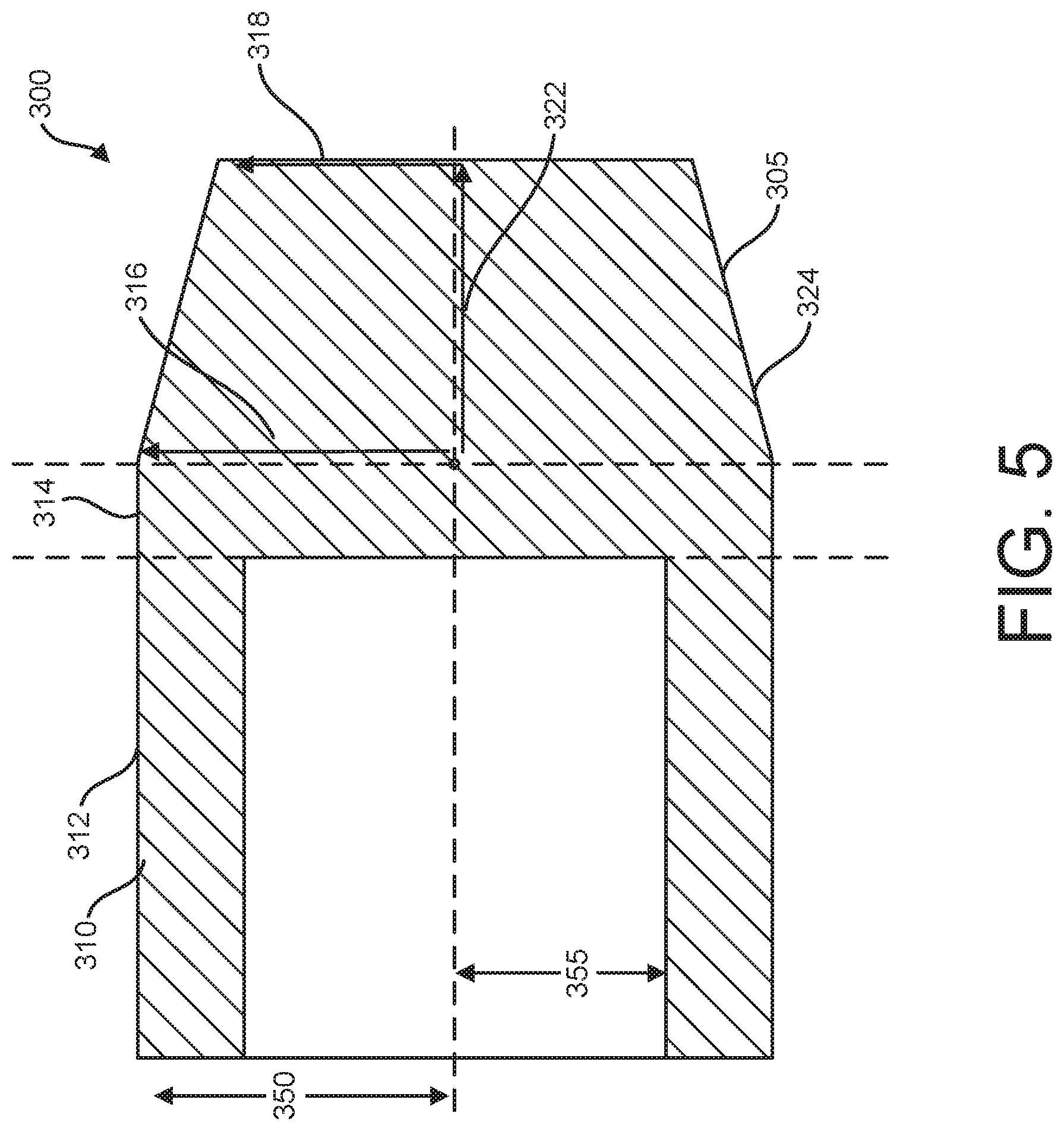
[0015] FIG. 5 is a cross section of a side view of another isolation device, according to one or more embodiments disclosed herein.
DETAILED DESCRIPTION
[0016] It is to be understood that the following disclosure describes several exemplary embodiments for implementing different features, structures, or functions of the invention. Exemplary embodiments of components, arrangements, and configurations are described below to simplify the present disclosure; however, these exemplary embodiments are provided merely as examples and are not intended to limit the scope of the invention. Additionally, the present disclosure may repeat reference numerals and/or letters in the various exemplary embodiments and across the Figures provided herein. This repetition is for the purpose of simplicity and clarity and does not in itself dictate a relationship between the various exemplary embodiments and/or configurations discussed in the various Figures. Moreover, the formation of a first feature over or on a second feature in the description that follows may include embodiments in which the first and second features are formed in direct contact, and may also include embodiments in which additional features may be formed interposing the first and second features, such that the first and second features may not be in direct contact. Finally, the exemplary embodiments presented below may be combined in any combination of ways, i.e., any element from one exemplary embodiment may be used in any other exemplary embodiment, without departing from the scope of the disclosure.
[0017] Additionally, certain terms are used throughout the following description and claims to refer to particular components. As one skilled in the art will appreciate, various entities may refer to the same component by different names, and as such, the naming convention for the elements described herein is not intended to limit the scope of the invention, unless otherwise specifically defined herein. Further, the naming convention used herein is not intended to distinguish between components that differ in name but not function. Additionally, in the following discussion and in the claims, the terms "including" and "comprising" are used in an open-ended fashion, and thus should be interpreted to mean "including, but not limited to." All numerical values in this disclosure may be exact or approximate values unless otherwise specifically stated. Accordingly, various embodiments of the disclosure may deviate from the numbers, values, and ranges disclosed herein without departing from the intended scope. Furthermore, as it is used in the claims or specification, the term "or" is intended to encompass both exclusive and inclusive cases, i.e., "A or B" is intended to be synonymous with "at least one of A and B," unless otherwise expressly specified herein.
[0018] Embodiments of the invention could be used in a variety of oil and gas applications, which could include both vertical and directional wells. Accordingly, position terminology such as "above" and "below" should be interpreted relative to the tubing string opening at the surface of the earth, where "above" is in a position closer to the opening at the surface of the earth, and "below" is in a position further from the opening at the surface of the earth. The terms "upstream" and "downstream" are to be interpreted relative to the direction of flow. Upstream is against the flow and downstream is with the flow. Accordingly, if component A is upstream of component B, component A is closer to the toe or end of the well then component B. The most upstream portion of the well is the end of farthest portion of the tubing string away from the surface.
[0019] Embodiments of the disclosure generally provide an isolation device that is compatible with a plug that may be used to isolate a production casing in a hydraulic fracturing process. The isolation device may replace a dissolvable frac ball that is dropped into a wellbore to seat in a plug to effect the isolation. The isolation device may include a first end that is hemispheric or a conical frustum and a second end that is cylindrical. The hemispheric or conical frustum first end of the isolation device may be seated in the plug. In one embodiment, the isolation device may be hollow and may be constructed of a dissolvable material. The isolation device may dissolve faster than a dissolvable frac ball, which results in a faster and more efficient hydraulic fracturing process, while eliminating the costs and risks associated with the traditional method of drilling out balls and plugs upon completion of a hydraulic fracturing process.
[0020] FIG. 1 is a cross-sectional view of a wellbore 10 with a plug 15 and an isolation device 100 for use in a hydraulic fracturing process, according to one or more embodiments disclosed herein. The wellbore 10, which is drilled into an earthen formation 20, may include a production casing 25 extending therethrough. The production casing may be encased in cement 30 to set the wellbore 10.
[0021] During a plug and perf operation of a hydraulic fracturing process, a plug 15 and one or more perforating guns (not shown) may be run into the production casing 25 to a first depth via a wireline or coiled tubing (not shown). The plug 15 may be set within the production casing 25 at the first depth, and the perforating guns may be fired to create perforations 35 in the production casing 25 and in the earthen formation 20. The wireline or coiled tubing with the perforating guns may be removed from the production casing 25, and the isolation device 100 may be sent down the production casing 25 to seat on the plug 15. When the isolation device 100 is seated on the plug 15, the perforated production casing 25 may be effectively isolated from the completion zone below the plug, as taken from the surface of the earth. Hydraulic fluids may then be pumped into the production casing 25 where the hydraulic fluids may flow out of the perforations 35 and into the earthen formation 20. The hydraulic fluids may fracture the earthen formation 20 thereby releasing hydrocarbons. Once treatment of the fractured area is complete, another plug and perf operation may be commenced at a second depth that is positioned above the first plug and perforated casing. As the plug and perf operation occurs, the isolation device may dissolve with continued contact with the wellbore fluids.
[0022] FIG. 2 is an isometric view of the isolation device 100, according to one or more embodiments disclosed herein. The isolation device may include a first end 105 that is hemispheric and a second end 110 that is cylindrical. The hemispheric first end 105 and the cylindrical second end 110 may be a monolithic piece or may be connected together by any suitable fastener or fastening method. The hemispheric first end 105 may be seated in the plug 15 shown in FIG. 1 during a plug and perf operation. In one embodiment, the isolation device 100 may be compatible with existing plugs for plug and perf operations.
[0023] In one embodiment, the isolation device 100 may consist of a dissolvable material. The dissolvable material may be a dissolvable plastic, such as polyglycolic acid ("PGA"), a dissolvable metal, such as magnesium aluminum alloy or aluminum alloy, any other dissolvable material suitable for a plug and perf operation, or a combination thereof.
[0024] FIG. 3 is a cross section of a side view of the isolation device 100, according to one or more embodiments disclosed herein. The hemispheric first end 105 may include a hemisphere outer radius 115, as taken from a central point of origin 125. In one embodiment, the hemisphere outer radius 115 may be compatible to seat with the plug 15 shown in FIG. 1, and less than one-half a diameter 40 of the production casing 25.
[0025] In one embodiment, the isolation device 100 may be hollow. In such embodiment, the hemispheric first end 105 may also include a hemisphere inner radius 120, as taken from the central point of origin 125. The hemisphere outer radius 115 may define a hemisphere outer surface area 130 of the hemispheric first end 105 and the hemisphere inner radius 120 may define a hemisphere inner surface area 135 of the hemispheric first end 105. Further, the hemisphere outer radius 115 and the hemisphere inner radius 120 may define a wall 140 of the hemispheric first end 105 with a wall thickness 145.
[0026] In one embodiment, the hemisphere outer radius 115 and the hemisphere inner radius 120 of the hemispheric first end 105 may be constant, and the wall thickness 145 of the wall 140 may also be constant or uniform. However, it is contemplated within the scope of the invention that the hemisphere inner radius 120 may vary.
[0027] Referencing FIGS. 2 and 3 together, in one embodiment, the hemisphere inner radius 120 of the hemispheric first end 105 may vary as a polar angle .phi. changes relative to the point of origin 125. In one embodiment, the hemisphere inner radius 120 of the hemispheric first end 105 may vary as an azimuth angle .theta. changes relative to the point of origin 125. In yet another embodiment, the hemisphere inner radius 120 of the hemispheric first end 105 may vary as both the polar angle .phi. and the azimuth angle .theta. changes.
[0028] Referring to FIG. 3, the cylindrical second end 110 may include a cylinder outer radius 150 and a cylinder inner radius 155 as taken from an axis y. The cylindrical second end 110 may include a length 160. The cylinder outer radius along the length 160 may define the cylindrical outer surface area 165, and the cylinder inner radius 155 along the length 160 may define the cylindrical inner surface area 170. Further, the cylinder outer radius 150 and the cylinder inner radius 155 may define a wall 175 of the cylindrical second end 110 with a wall thickness 180. In one embodiment, the cylinder outer radius 150 may be equivalent to the hemisphere outer radius 115. In one embodiment, the wall thickness 145 of the hemispheric first end 105 may be constant and uniform. Further, the wall thickness 145 of the hemispheric first end 105 may be substantially the same (within +/-10%) as the wall thickness 180 of the cylindrical second end 110.
[0029] In another embodiment, the cylinder inner radius 155 may vary along the length 160 of the cylindrical second end 110. Accordingly, as the cylinder inner radius 155 varies along the length 160 of the cylindrical second end 110, the wall thickness 180 also varies along the length 160 of the cylindrical second end 110.
[0030] In one embodiment, the length 160 of the cylindrical second end 110 may be determined such that the isolation device 100 remains oriented with the hemispheric first end 105 pointed downhole towards the plug 15 when it is sent down the production casing 25, as shown in FIG. 1. In one embodiment, the length 160 may be at least longer than the hemisphere outer radius 115. In one embodiment, the isolation device 100 may have a device length 185 that is greater than an inner diameter 40 of the production casing 25. In one embodiment, the device length 185 may be equal to the hemisphere outer radius 115 and the length 160 of the cylindrical second end 110 combined.
[0031] FIG. 4 is a cross section of a side view of another isolation device 200, according to one or more embodiments disclosed herein. The isolation device 200 is similar to the isolation device 100 shown in FIG. 3, except the hemispheric first end 205 may be substantially solid and may have no inner radius. Instead, the hemispheric first end 205 may include a hemisphere outer radius 215, as taken from a central point of origin 225. In one embodiment, the hemisphere outer radius 215 may be compatible to seat with the plug 15 shown in FIG. 1, and less than one-half a diameter 40 of the production casing
[0032] The hemisphere outer radius 215 may define a hemisphere outer surface area 230 of the hemispheric first end 205, and a volume 242 of the hemispheric first end 205 may further be defined by the hemisphere outer radius 215. The cylindrical second end 210 may be substantially the same as disclosed with respect to the isolation device 100 shown in FIG. 3. The hemispheric first end 205 may include an inner surface area 235 as defined by a cylinder inner radius 255 as determined at an axis 190 where the cylindrical second end 210 connects to the hemispheric first end 205. The cylindrical second end 210 may include a cylinder outer radius 250.
[0033] FIG. 5 is a cross section of a side view of another isolation device 300, according to one or more embodiments disclosed herein. The isolation device 300 is similar to the isolation device 200 shown in FIG. 4, except the first end 305 may be tapered to form a a conical frustum as shown in FIG. 5. As shown, the first end 305 may be solid. However, it is within the scope of the invention that the first end 305 may be hollow like the isolation device 100 shown in FIG. 3. It is also within the scope of the invention that the first end 305 may be conical. The first end 305 may be compatible to seat with the plug 15 shown in FIG. 1.
[0034] In one embodiment, the isolation device 300 may have an area where a cylindrical second end 310 has a hollow portion 312 and a solid portion 314. The hollow portion 312 may be defined by a cylinder outer radius 350 and a cylinder inner radius 355 while the solid portion 314 may be defined by the cylinder outer radius 350.
[0035] In one embodiment, the conical frustum may be defined by a first radius 316 at a first plane and a second radius 318 at a second plane. The two planes may be separated by a height 322. The outer portion between the first radius 316 and the second radius 318 may form a tapered surface 324. In one embodiment, the first radius 316 may be the same as the cylinder outer radius 350. In one embodiment, the second radius 318 may be the same as the cylinder inner radius 355. However, the second radius 318 may be any radius shorter than the first radius 316 that may seat with the plug 15 shown in FIG. 1.
[0036] The isolation devices 100, 200, and 300 shown in FIGS. 3, 4, and 5 include a greater total surface area than a frac ball with a radius equivalent to the hemisphere outer radius 115 and 215 or to a radius of that between the first radius 316 and the second radius 318 of a conical frustum. Because the isolation devices 100, 200, and 300 include a greater surface area, the isolation devices 100, 200, and 300 may dissolve faster when in contact with wellbore fluids. Additionally, in one embodiment, the isolation devices 100, 200, and 300 may also have a total volume that is less than the frac ball with a radius equivalent to the hemisphere outer radius 115, 215 or to a radius of that between the first radius 316 and the second radius 318 of a conical frustum. Such embodiment of the isolation devices 100, 200, and 300 also leads to a faster dissolution time when the isolation devices 100, 200, 300 are in contact with wellbore fluids. The faster dissolution time may lead to a faster and more efficient plug and perf operation. In other words, the surface area of a ball decreases over time thus slowing down the dissolution volume over time. By creating an internal area of the device, the surface area increases as it dissolves thus increasing the dissolution volume over time.
[0037] While the isolation devices disclosed herein have described a first end as hemispherical, it is contemplated within the scope of the invention that the first end may be a spherical cap (not shown). In such embodiment, the spherical cap may be compatible with seating in the plug 15 shown in FIG. 1 to isolate the wellbore 10 from the completion below. The spherical cap may be hollow or solid. It is further contemplated within the scope of the invention that the hemispherical first end 105 may have a different internal profile at the location where the hemispherical first end 105 connects to the cylindrical second end 110 (not shown).
[0038] The foregoing has outlined features of several embodiments so that those skilled in the art may better understand the present disclosure. Those skilled in the art should appreciate that they may readily use the present disclosure as a basis for designing or modifying other processes and structures for carrying out the same purposes and/or achieving the same advantages of the embodiments introduced herein. Those skilled in the art should also realize that such equivalent constructions do not depart from the spirit and scope of the present disclosure, and that they may make various changes, substitutions and alterations herein without departing from the spirit and scope of the present disclosure.
* * * * *
D00000
D00001
D00002
D00003
XML
uspto.report is an independent third-party trademark research tool that is not affiliated, endorsed, or sponsored by the United States Patent and Trademark Office (USPTO) or any other governmental organization. The information provided by uspto.report is based on publicly available data at the time of writing and is intended for informational purposes only.
While we strive to provide accurate and up-to-date information, we do not guarantee the accuracy, completeness, reliability, or suitability of the information displayed on this site. The use of this site is at your own risk. Any reliance you place on such information is therefore strictly at your own risk.
All official trademark data, including owner information, should be verified by visiting the official USPTO website at www.uspto.gov. This site is not intended to replace professional legal advice and should not be used as a substitute for consulting with a legal professional who is knowledgeable about trademark law.