Glazing Assembly
RITCHIE; Ian
U.S. patent application number 16/484601 was filed with the patent office on 2020-02-06 for glazing assembly. This patent application is currently assigned to IAN RITCHIE ARCHITECTS LTD.. The applicant listed for this patent is IAN RITCHIE ARCHITECTS LTD.. Invention is credited to Ian RITCHIE.
| Application Number | 20200040575 16/484601 |
| Document ID | / |
| Family ID | 58462507 |
| Filed Date | 2020-02-06 |
| United States Patent Application | 20200040575 |
| Kind Code | A1 |
| RITCHIE; Ian | February 6, 2020 |
Glazing Assembly
Abstract
A glazing assembly is disclosed, the assembly comprising first and second toughened glass members. Each member comprises a sheet with first and second flanges projecting from opposite ends of the sheet in a direction substantially perpendicular to the sheet, and the first and second flanges of the first member are joined respectively to the first and second flanges of the second member by first and second connector portions such that the first and second flanges of the first member are substantially coplanar with the first and second flanges of the second member, respectively. A modular glazing array is also disclosed. The array comprises a plurality of glazing assemblies arranged side by side, such that at least one pair of joined, coplanar flanges of each of the plurality of glazing assemblies faces a pair of joined, coplanar flanges of another of the plurality of glazing assemblies.
| Inventors: | RITCHIE; Ian; (London, GB) | ||||||||||
| Applicant: |
|
||||||||||
|---|---|---|---|---|---|---|---|---|---|---|---|
| Assignee: | IAN RITCHIE ARCHITECTS LTD. London GB |
||||||||||
| Family ID: | 58462507 | ||||||||||
| Appl. No.: | 16/484601 | ||||||||||
| Filed: | February 8, 2018 | ||||||||||
| PCT Filed: | February 8, 2018 | ||||||||||
| PCT NO: | PCT/GB2018/050356 | ||||||||||
| 371 Date: | August 8, 2019 |
| Current U.S. Class: | 1/1 |
| Current CPC Class: | E04C 1/42 20130101; E04C 2/54 20130101 |
| International Class: | E04C 2/54 20060101 E04C002/54; E04C 1/42 20060101 E04C001/42 |
Foreign Application Data
| Date | Code | Application Number |
|---|---|---|
| Feb 8, 2017 | GB | 1702035.5 |
Claims
1. A glazing assembly comprising: first and second toughened glass members, each member comprising a sheet with first and second flanges projecting from opposite ends of the sheet in a direction substantially perpendicular to the sheet, wherein the first and second flanges of the first member are joined respectively to the first and second flanges of the second member by first and second connector portions such that the first and second flanges of the first member are substantially coplanar with the first and second flanges of the second member, respectively.
2. The glazing assembly according to claim 1, wherein each connector portion comprises first and second channels, and is disposed between two opposing flanges such that an edge of a flange of each of the first and second members is held within each of the first and second channels, respectively.
3. The glazing assembly according to claim 1, wherein each connector portion is disposed along two opposing flange edges of the first and second members.
4. The glazing assembly according to claim 1, wherein each connector portion comprises a thermal insulator.
5. The glazing assembly according to claim 1, wherein each connector portion is bonded to an edge of a flange of each of the first and second members by an adhesive.
6. The glazing assembly according to claim 1, wherein the dimensions of the first member are substantially the same as those of the second member.
7. The glazing assembly according to claim 1, wherein for each member the depth of each flange is between approximately 8% and 30% of the width of the sheet.
8. The glazing assembly according to claim 1, wherein for each member the height of the sheet is greater than 3.3 m, and the width of the sheet is approximately 10% of the height of the sheet.
9. The glazing assembly according to claim 1, wherein the members are attached together so as to define a tube having a substantially rectangular cross section, with sides defined by the flanges and sheets of the first and second members.
10. The glazing assembly according to claim 9, further comprising a closure sealing an end of the tube.
11. The glazing assembly according to claim 1, wherein the volume between the first and second members comprises a thermal insulator.
12. The glazing assembly according to claim 1, wherein the volume between the first and second members comprises an acoustically insulating material.
13. The glazing assembly according to claim 1, wherein the volume between the first and second members comprises a material through which light is diffusely transmitted.
14. The glazing assembly according to claim 11, wherein the material comprises glass fibre.
15. The glazing assembly according to claim 1, wherein an outer surface of a sheet of the assembly comprises a plurality of grooves aligned substantially parallel to the flanges of the assembly.
16. The glazing assembly according to claim 1, wherein an outer surface of a sheet of the assembly has a rough profile which scatters light transmitted through the surface.
17. The glazing assembly according to claim 1, further comprising an internal protective element.
18. The glazing assembly according to claim 17, wherein the internal protective element is formed from a polycarbonate material.
19. The glazing assembly according to claim 17, wherein the internal protective element comprises a sheet portion that is substantially coplanar with the sheet of the first and second members and spans the interior volume defined by the first and second members.
20. A method of producing a glazing assembly, the method comprising: providing first and second toughened glass members, each member comprising a sheet with first and second flanges projecting from opposite ends of the sheet in a direction substantially perpendicular to the sheet, and joining the first and second flanges of the first member respectively to the first and second flanges of the second member using first and second connector portions such that the first and second flanges of the first member are substantially coplanar with the first and second flanges of the second member, respectively.
21. The method according to claim 20, wherein each connector portion comprises first and second channels, and the method further comprises disposing each connector portion between two opposing flanges such that an edge of a flange of each of the first and second members is inserted into and held within each of the first and second channels, respectively.
22. The method according to claim 20, further comprising disposing each connector portion along two opposing flange edges of the first and second members.
23. The method according to claim 20, further comprising bonding each connector portion to an edge of a flange of each of the first and second members using an adhesive.
24. the method according to claim 20, comprising attaching the members together so as to define a tube having a substantially rectangular cross section, with sides defined by the flanges and sheets of the first and second members, and further comprising sealing an end of the tube with a closure.
25. A modular glazing array comprising: a plurality of glazing assemblies according to claim 1 arranged side by side, such that at least one pair of joined, coplanar flanges of each of the plurality of glazing assemblies faces a pair of joined, coplanar flanges of another of the plurality of glazing assemblies.
26. The modular glazing array according to claim 25, wherein the plurality of glazing assemblies comprises three or four glazing assemblies, and wherein the modular glazing array comprises a window within the module.
27. The modular glazing array according to claim 25, wherein a sealant is disposed between adjacent assemblies.
28. The modular glazing array according to claim 25 wherein the normal vectors of the sheets of adjacent assemblies differ by no more than 10.degree..
29. The modular glazing array according to claim 25, wherein the sheets of each of the plurality of assemblies are substantially parallel.
30. A method of installing a glazing assembly according to claim 1, the method comprising: providing a front-loading carrier for receiving the glazing assembly, the carrier comprising a frame having a height corresponding to that of the assembly, a surrounding lip on a rear side of the carrier, and a removably mounted lip on the front side of the carrier, inserting the glazing assembly into the frame from the front side when the removable lip is removed, and mounting the lip on the carrier such that the assembly is prevented from being removed from the frame.
31. A method of installing a modular glazing array according to claim 25, the method comprising: providing a front-loading carrier for receiving the modular glazing array, the carrier comprising a frame having a size and shape corresponding to the height of the array, a surrounding lip on a rear side of the carrier, and a removably mounted lip on the front side of the carrier, inserting the array into the frame from the front side when the removable lip is removed, and mounting the lip on the carrier such that the array is prevented from being removed from the frame.
Description
FIELD OF THE INVENTION
[0001] The present invention relates to a glazing assembly comprising first and second toughened glass members. In particular, the invention relates to an assembly wherein first and second toughened glass members are joined together such that the structural performance of the assembly is improved.
[0002] BACKGROUND TO THE INVENTION
[0003] U-channel cast glass is a low-cost cladding material which has been available on the market for over four decades. These U-channels comprise a strip of glass bent or moulded in a U-shape, typically using a machine rolling process, and generally come in a set number of profiles and widths which are broadly homogenous across manufacturers worldwide. Widths available are generally circa 232 mm, 262 mm and 330 mm. As a general principle, the wider the U-channel, that is the greater the distance across the central sheet or between the return flanges, the less vertical distance it can span. Furthermore, wider U-channels generally require the return flanges to be more shallow, that is extending less far in the direction in which they project from the sides of the sheet in proportion to the width of the sheet.
[0004] In the last decade, advances in the toughening (tempering) process has improved and removed the need for casting metal wire support into the channels to strengthen the span. This has also allowed toughened U-channel glass to be installed at high levels because it can break safely.
[0005] The dielectric (insulating) properties of glass in buildings first surfaced as a need in the early part of the 20th century. Examples of double facades using two layers of single glazing first appeared in Russia in the 1920s. However, these early examples failed to account for glass having virtually no dielectric property, and in such arrangements, the single outer window will quickly reach the same temperature as the outside.
[0006] At a similar time, the idea of having a sealed unit of two skins of glass separated by air was put forward, and the first product was manufactured in 1944 using a welded glass spacer. A double wall with the outer wall double-glazed provides a thermally efficient arrangement. However, cost starts rising dramatically. This, coupled with access between the panes being limited, further complicates the facade construction and begins to reduce the useable floor area of the building.
[0007] Today, thermal performance of triple glazed insulated glass units can achieve insulating properties with U Value of 0.8 W/m.sup.2K. But the cost of production, and the weight of the unit, which typically includes 12 mm glass+16mm air+6 mm glass+16 mm air+6 mm glass precludes much use of it. And ultimately with all insulated glazing units (IGUs) the boundary seals fail over time.
[0008] Historically, glass facades were used when little thermal insulation was required and this led to the development, in the early 1980s, of structural glazing. The system designed by Rice Francis Ritchie for the Bioclimatic Facades at the Cite des Sciences, La Villette, France, relies upon an innovative articulated stainless steel ball-joint fixing through a machined countersunk hole in the toughened float glass and separated by pure aluminium washers. The articulation avoids bending stresses in the glass and the fixing can carry up to 4 tonnes (40 kN). A similar system but with much less loading capacity (approximately 0.7 tonnes: 7 kN)--is Pilkington Planar, formed of float toughened glass panels held by fixed bolts--a "point-fixed" system to create a structural glass "wall". The continued appeal of such a system among architects focuses on the transparency of the assembly and a seemingly "frameless" structure.
[0009] By contrast, cast glass U-channels require a series of support channels connected by movement joints instead of struts or trusses. Currently, U-channels can be installed in a variety of ways depending on requirements, vertically or horizontally, in single profile, wherein glazing consists of a single layer of U-channels, or an "interlocked" double profile, wherein U-channels are arranged in two opposing layers typically such that their flanges are overlapping or abutting.
[0010] Additionally, current manual techniques for installing U-channels in these arrangements, and the amount of on-site assembly and sealing that is required, make the system susceptible to contamination by construction site materials and insects.
[0011] Therefore a need exists for a glazing assembly utilising glass that can provide increased structural performance, as well as thermal performance and protection against on-site contaminants, while being suitable for rapid, large-scale installation and to allow aluminium-framed windows and external louvers to be integrated into the module without the need to introduce any additional structural support element.
SUMMARY OF THE INVENTION
[0012] In accordance with the invention there is provided a glazing assembly comprising first and second toughened glass members, each member comprising a sheet with first and second flanges projecting from opposite ends of the sheet in a direction substantially perpendicular to the sheet, wherein the first and second flanges of the first member are joined respectively to the first and second flanges of the second member by first and second connector portions such that the first and second flanges of the first member are substantially coplanar with the first and second flanges of the second member, respectively.
[0013] The members may therefore be arranged such that the flanges of each member are projecting towards, and opposing, the flanges of the other member, and may be attached together by a first and a second connector portion between the first and second flanges of each member, respectively. In other words, the members may be arranged such that the sheets of the members are opposing, and the flanges of each member project inwardly towards the flanges of the other member, and wherein the inwardly facing edge of each flange of the first member is joined to the inward facing edge of the opposing flange of the second member by a connector portion. In this sense, the direction described as inward refers to the direction pointing towards the centre or centre plane of the assembly, or equivalently pointing from each member towards the opposing member.
[0014] Typically, and in particular where a flat or planar glazing facade or facade components are required, the sheet of one or both of the first and second member is planar. The sheet of one or both of the first and second members may be a web. The members may be arranged such that the sheets of the first and second member are substantially parallel to one another, as well as the flanges of the first and second member being aligned. In some embodiments, the sheets and flanges of the first member are substantially parallel to the sheet and flanges of the second member, respectively, and an edge of each of the first and second flanges of each member faces, and is joined by a connector portion to, and an edge of a flange of the other member. In other words, the members may be attached together by first and second connector portions joining the first and second flanges of the first member to the first and second flanges of the second member, respectively. In this way, the first and second members may be attached together by way of a connector portion joining an edge of each flange of the first member to a facing edge of each flange of the second member.
[0015] Typically, each member is formed as a U-channel, or U-shaped channel, or a girder, beam, strut, or other type of elongate member having a cross section perpendicular to the elongate access that is substantially U-shaped. U-profile glass, or U-channel glass, is widely used in architectural applications. These U-shaped sections generally comprise a central sheet with flanges projecting upwards, or orthogonally, along either edge of the sheet, with each flange terminating at an edge face. These edge faces may have a normal vector parallel to the direction substantially perpendicular to the sheet, or to the direction in which the first and second flanges project from the opposite ends of the sheet. The U-channel members of the present arrangement may therefore be held together in an opposing arrangement such that the ends, or edge faces of the first and second flanges of the first member oppose the ends or edge faces of the first and second flanges of the second member. Thus a toe-to-toe, or edge-to-edge arrangement may be provided, wherein the edge faces of the first and second flanges of the first member are opposing, or are aligned with, the edge faces of the first and second flanges of the second member, that is the edges of the flanges of the first member face the edges of the flanges of the second member.
[0016] Typically, therefore, the flanges of each member do not overlap the flanges of the other member. The U-channels are arranged with their flanges edge-to-edge such that the depth of the glazing assembly includes the total depth of each pair of flanges, meaning that the assembly depth includes twice the depth of a single flange if the flanges are the same depth for each of the first and second member. The term depth is used here to refer to the extent or linear size of the assembly in the direction perpendicular to the sheets. Typically, the volume occupied by, or defined by, each of a single U-channel and the glazing assembly has dimensions such that the depth as defined in this way is the smallest dimension.
[0017] The members are arranged such that the flanges of each member project, in the direction of the depth of the U-channel and assembly, towards the flanges of the other member, and each flange of the first member is bonded to a flange of the second member by a connector portion.
[0018] The assembly is typically installed as glazing on a building, with the assembly oriented such that the outer face of the sheet of one member faces outwards from the building, and the outer face of the sheet of the other member faces towards of the interior of the building. The outer face of the sheet of each member in the assembly is that which faces away from the other member and away from the interior of the assembly. Thus the assembly can function as a panel in a glazing facade. The issues inherent to working with U-channel cast glass, for example, have been addressed by the present arrangement by a way of unitising and modularising the building envelope. This has been made possible due to the strength which has been found to be achieved by structurally bonding the U-channels together with a purpose made polyamide thermal break. This will allow, subject to wind load criteria, greatly increased structural spans. Bonding the two U-channels together in a flange-to-flange arrangement provides increased structural strength compared with prior art geometric arrangements, such as those wherein two U-channels are interlocked such that one of the flanges on each member abuts the sheet of another member.
[0019] The reason for this improvement is the inherently stronger structure achieved by attaching the flanges in an edge-to-edge arrangement. This provides the assembly with increased depth, and a more square cross section, than the interlocked arrangement formed from U-channels of the same or equivalent dimensions. This increases the resistance to force applied to the assembly, for example wind load, owing to there being more material to resist in the depth axis of the assembly. This advantageous effect may also be understood in terms of the additional squareness or depth provided by arranging two U-channels of given dimensions in a toe-to-toe arrangement rather than an interlocking arrangement approximately doubling the depth of the assembly while effectively halving the thickness of each flange (since the flanges are in single thickness and non-overlapping). This results in a greater section modulus, which is related to the strength or load capacity of the assembly, and its resistance to bending or failure.
[0020] This effect, of increasing the structural capacity of a hollow rectangular tube formed by an attached pair of glass U-channels is a key advantage provided by the assembly. This has previously not been achievable with interlocked arrangements, owing to the depth of the overall assembly being limited ultimately by the depth of the flanges, that is their extent in the direction in which they project from the sheet. The process of casting glass U-channels and forming the flanges and flange edges inherently imposes an upper limit upon U-channel depth, that is flange extent.
[0021] Constructing the assembly from members that are formed from, or comprise, toughened or tempered glass contributes to the mechanical strength of the assembly and therefore to the advantageous structural capability it provides. Such glass may be produced by way of applying thermal or chemical treatments to the cast glass U-channels, for example, so as to put the outer surfaces of the members into compression and the centre or interior of the member, that is the glass between those outer surfaces, into tension.
[0022] Typically, the glass members are toughened by way of a heat treatment process wherein each cast glass member is caused to travel through a tempering oven. Thus the glass is typically heated to a temperature in excess of 600.degree. C. Preferably this comprises raising the glass temperature to 620.degree. C. The glass then typically undergoes a quenching procedure, which comprises cooling the glass under high pressure, or pressure in excess of atmospheric pressure. This typically comprises directing jets or streams of high-pressure air at the member from an array of nozzles so as to blast the surface of the glass. This causes the outer surfaces of the glass to cool at a faster rate than the centre. As the centre of the glass cools, it pulls back from the outer surfaces. As a result, the centre remains in tension, and the outer surfaces remain in compression, which affords tempered glass its increased strength.
[0023] In some embodiments the glass of the members is toughened by way of chemical tempering, wherein chemicals are caused to exchange ions on the surface of the glass in order to create compression, thereby achieving increased strength. In embodiments comprising cast glass members, such chemical toughening processes are typically not used, but rather toughening is performed by way of heat treatment.
[0024] A toughened glass member having these properties typically possesses far greater mechanical strength than an equivalent member formed from annealed or non-toughened glass. For example, while annealed glass may break when subjected to a pressure of around 6,000 pounds per square inch (psi) or around 41 MPa, toughened glass typically breaks at an applied pressure of approximately 24,000 psi or 165 MPa. The toughened glass members of the assembly may be selected, or the toughening treatment applied to them, may be based at least in part upon their being able to withstand pressure up to such a maximum value.
[0025] The increased strength, load capacity, and resistance to movement provided by the assembly allow it to be used structurally. For U-channels of given dimensions, the possible vertical span of the assembly, when arranged so that the tube formed by the attached U-channels is aligned vertically, is vastly increased with respect to prior art geometric arrangements.
[0026] In typical embodiments, one or each of the first and second members of the assembly comprise or are formed from toughened cast glass. It is also envisaged, however, that the members may comprise or be formed from other types of toughened glass. Types of toughened glass that may be used to form the members additionally include: crown glass, cylinder glass, cast plate glass, polished plate glass, rolled plate glass, drawn sheet glass, and float glass.
[0027] The first and second flanges of the first member being substantially coplanar with the first and second flanges of the second member, respectively, typically means that each flange is aligned substantially in the same plane as the opposing flange to which it is joined. Thus each joined pair of flanges forms a side of the tubular assembly, with the substantially rectangular tube having a depth greater than or equal to the total depth of both members, the depth of each member being defined by the depth of the flanges. The substantially coplanar arrangement includes the possibility that there may be a slight offset or lateral misalignment between joined flanges such that they are not perfectly coplanar. In such arrangements, the edge faces of opposing, joined flanges might not be perfectly aligned. Nevertheless, such arrangements, when maintaining the toe-to-toe arrangement may still be considered as having substantially coplanar joined flanges and would achieve the strengthening effect of joining the opposing flanges end-to-end so as to form a tubular structure of increased depth. This tubular structure, in embodiments wherein the flanges are differently aligned owing to an offset between the first and second members or a difference in size between the flange to flange widths of the first and second members, would have a discontinuity in one or both sides of the tubular structure, at the region where the flanges are joined to one another.
[0028] In typical embodiments, the first and second connector portions comprise first and second connectors respectively. Thus a first connector may be disposed at the interface between the first flange of the first member and the first flange of the second member, and a separate, second connector may be disposed at the interface between the second flange of the first member and the second flange of the second member.
[0029] In some embodiments, the first and second connector portions comprise first and second portions of a first connector. The first connector portion may be linked or connected to the second connector portion by a linking portion, two linking portions, or a plurality of linking portions. The first and second connector portions may thus be formed from a unitary piece or extrusion, or may be formed from two or more separate pieces that are bonded or adhered together. A linking portion may join the first and second connector portions between respective ends of the first and second connector portions. A linking portion may be disposed across an end or opening of a tubular structure formed by the assembly, or across the interior volume of the assembly.
[0030] Typically, the connector portion disposed between each joined pair of flanges comprises a polymer. Preferably, the material from which the connector portions are formed comprises a polyamide, and more preferably each connector portion is formed as a polyamide extrusion. The polymer may typically comprise in epoxy, vinylester, or polyester thermosetting plastic. More preferably, a connector portion may comprise a fibre-reinforced polymer. The fibres in such embodiments may comprise glass, carbon, basalt or synthetic fibres.
[0031] Preferably, the material from which each or both of the first and second connector portions is formed has any one or more of the following mechanical properties: tensile strength in the range 60-240 Nmm.sup.-2, more preferably at least 110 Nmm.sup.-2; modulus of elasticity in tension of at least 6,000 Nmm.sup.-2; flexural modulus in the range 1.3-19.0 GPa, and more preferably in the range 4-8 GPa; flexural strength in the range 80-260 Nmm.sup.-2 and more preferably 110-210 Nmm.sup.-1; and tensile strain at break of at least 2.5%. The material is typically a polymer, or preferably a polyamide, or a thermoplastic, and is may be selected based upon the material having such mechanical properties, typically for the dry material as moulded and at 23.+-.2.degree. C., according to testing standard ISO 527. For example, TECATHERM 66 GF, designation Thermoplastic ISO 1874-PA 66-HI,EC2L, GF25, or polyamide 66 with 25.0.+-.2.5% by weight glass fibres may be selected for the connecting portions, in accordance with these requirements.
[0032] Preferably the material of the connector portions is selected so as to avoid the connector portions displaying rubber-like elasticity. For this reason it is preferable to select a polymer that is, or is substantially, inelastic , that is a non-elastomer. The result is that the connector portions are capable of no or negligible segmental motion, at the relevant temperature ranges of use. The preferable advantageous stiffness of the connector material may be achieved by selecting a connector portion material having a Young's modulus in the range 1,700-2,000 MPa. More preferably the connector portions are formed from a material having a Young's modulus of 1,850 MPa. Such a selection of material can result in a substantially non-deformable connector portion and thereby in the prevention, reduction or elimination of deformation of the connector portions when the assembly is subjected to wind loads and vertical loads.
[0033] As indicated above, two U-channel members according to the present disclosure may advantageously behave as a composite profile. In combination with this, the connector portions, which are typically formed from polyamide extrusion, adhered with an adhesive such as structural silicone, may provide an improved area moment of inertia in comparison with a weak composite effect which would be achieved with less stiff, and more deformable and elastic connector portions.
[0034] The area moment of inertia of two U-channel members connected by a such an alternative, less stiff connector such as one formed from rubber material would be approximately in the range 140-145 cm.sup.4. The theoretical area moment of inertia of a perfectly stiff assembly would be 2,873 cm.sup.4.
[0035] The presence of a connector portion disposed between each pair of opposing flanges serves to provide impact protection for the assembly. That is, any impact or sudden acceleration or movement experienced by a member with respect to the opposing member cannot result in the opposing members, and in particular the flanges thereof, impacting one another, since each connector portion lies between the opposing flange edges which would otherwise be liable to impact one another in absence of the connector portions should the members be moved towards one another. Conversely, interlocked arrangements of the prior art are afforded no such impact protection, since the glass members typically directly contact one another, or might be separated from one another by adhesive which provides little or no impact protection. Thus a further advantage provided by the present arrangement over the prior art can be seen.
[0036] In some embodiments, each connector portion comprises first and second channels, and is disposed between two opposing flanges such that an edge of a flange of each of the first and second members is held within each of the first and second channels, respectively. In other words, the connector portions typically join the members together along the edges of the flanges. Each channel may be shaped or adapted to receive an edge, or an end or edge face of a flange. Each channel may be further adapted to grip an edge portion of a flange, for example a channel may comprise a gripping portion. In this respect, the channel itself, or the separation between an upper or outer portion of the sides of the channel, may be narrower than the thickness of the edge of a flange to be received, and in combination with this, the sides of the channel, or the whole connector portion itself, may be formed from a flexible material. In such embodiments, the sides of the channel of the connector portion may flex a little outwards to receive the flange edge and would exert an inward restoring force upon the inserted flange such that it is gripped or held by the sides of the channel. The connector portion sides may, in some embodiments, be forcibly rotated outwards. In preferred embodiments, however, the connector material is instead chosen to be inflexible, having a high degree of stiffness so as to contribute to the structural capability of the assembly.
[0037] A gripping portion of a connector portion channel could comprise at least one tooth or protrusion which is attached to or formed from, and projecting from the inside of, the channel and is arranged to provide resistance against the flange moving outwards from the channel. The inclusion of sawteeth or a sawtooth surface profile on the inside of the channel that engages with the flange is preferable, since it may improve the mechanical connection to the flange or, in particular, to the bonding material or adhesive.
[0038] Typically, a connector portion has such a channel on each opposing side, so as to receive two flanges from two opposing directions. The connector portion may comprise a piece of solid material, or a solid strip, with a substantially H-shaped cross section perpendicular to the edges of the flanges, or perpendicular to the elongate axis defined by the length or largest dimension of the connector portion. It is further envisaged that a connector portion may have a different shaped cross section, such as that of a flat strip or an L-shape, or two attached
[0039] U-shaped sections arranged back to back so as to receive a flange edge in each U-section channel.
[0040] The connector portions, and in particular the channels thereof, may be joined to flanges with adhesive or another bonding material. As an alternative, or additionally, all or a part of the length of the flange edges may be held together by a connector portion or several connector portions comprising a clamp, or a double sided clamp.
[0041] Typically, each connector portion is disposed along two opposing flange edges of the first and second members. The connector portions being disposed along and between the end edges or faces of opposing flanges means that the connector portions may be held together in an edge-to-edge arrangement to form an assembly with a rectangular profile in which the length of the perimeter of the rectangular profile is maximised. The connector portions being attached to the members, and serving to attach the members together, along the length of the flange edges results in the edge-to-edge bonding which gives rise to the increased strength of the assembly being applied along the length of each flange edge. Preferably, each connector portion, or in particular each connector channel, has a length equal to, or in some embodiments greater than, the length of the flange edge inserted therein.
[0042] Preferably, each connector portion has an elongate structure and each channel of each connector portion is aligned with this elongate axis. Each connector portion may comprise a first and second channel, wherein an edge of a flange of each of the first and second members is held by the first and second channels, respectively. Thus, it is preferable that the connector portion is sufficiently long to hold a flange edge along its entire length. This is advantageous in that the resistance to the separation of members is maximised. Additionally, the connector portion also serves to seal the assembly against contamination and fluid penetration, and so disposing this sealing connector portion along the entire length of each interface between opposing flanges maximises this sealing effect.
[0043] Typically, each connector portion comprises a thermal insulator. The thermal insulator is typically between the first and second channels which receive or hold the flange edges. Thus, the conduction of heat between the flanges of the first and second members is minimised. This is advantageous in architectural applications, such as when the assembly is installed on the outside of a building as a glazing panel, which require limiting the conduction of heat from one side, corresponding to the sheet of one member, to the other side, corresponding to the sheet of the other member.
[0044] The insulator may comprise a void, gap or cavity formed in the connector portion. The presence of a void may reduce the thermal conduction through the material from which the connector portion is formed. The void may contain air or one or more gases, or may be a partial vacuum or low-pressure environment with gas density lower than atmospheric air density. The thermal insulator may comprise a thermally insulating material such as polyamide, polystyrene, polyurethane, or other polymer wool. Such materials would serve to reduce the degree of heat conduction from one member to the other by providing a thermal break or minimising thermal contact or transmission along the interface where the two members are connected or joined.
[0045] The two members being joined to one another by the connector portions may comprise the members being attached, connected, affixed, fastened, or adhered in various ways. Typically, each connector portion is bonded to an edge of a flange of each of the first and second members by an adhesive. Preferably the adhesive comprises a silicone material. More preferably, the adhesive comprises a structural sealant or a glazing sealant, and may be a structural bonding adhesive. More preferably still, the adhesive comprises a neutral curing silicone formulation suitable for the structural bonding of glass and other building components.
[0046] Typically, the adhesive is disposed within the receiving portion or channel within which each flange edge is inserted into the connector portions. This advantageously provides a sufficiently strong or structural bond between each member and the connector portions, and thereby, between the two members via the connector portion, so as to allow the assembly to function as a singular structural unit.
[0047] Typically, the dimensions of the first member are substantially the same as those of the second member. That is the size and shape of each of the flanges of the first member and the sheet of the first member are the same as those of the flanges and sheet of the second member, respectively. In particular, the sheet width, which may be defined as the linear separation between the flanges of each member, is the same for both members so that the flanges can be aligned between the two members. Additionally, since it is preferable to maximise the depth of the flanges in order to, in turn, maximise the depth of the assembly overall, each member will have flanges whose depth corresponds to the maximum possible depth achievable using the casting method of preparing glass U-channels. Therefore, it is ideally preferable that the depth of these flanges be the same for the first and second members.
[0048] Likewise, the height of the first and second members, that is the linear extent of the members in a direction perpendicular to the depth and the width as defined above, is preferably the same for both members.
[0049] Typically, for each member the depth of each flange is between approximately 8% and 30%, or between approximately 15% and 30% of the width of the sheet. Such aspect ratios are typical for the cross sections of cast glass U-channels. For example, U-channels are available having flange depths of 41-60 mm, and 70 mm, with typical sheet widths of 232 mm, 262 mm, 330 mm, and 500 mm being typically available.
[0050] Typically, for each member, the height of the sheet is greater than 3.3 m, and the width of the sheet is approximately 10% of the height of the sheet. Thus, the present arrangement provides an aspect ratio that can be achieved in the plane of an assembly panel combined with a vertical span greater than that which was possible with prior art assemblies. Effectively, the increased structural strength of the assembly permits a greater range of heights, widths, and relative proportions than those which were possible previously.
[0051] For instance, previously, U-channels having a height sufficient to span between the floors of a building would need to be approximately 0.25 m wide under typical load conditions.
[0052] The present glazing assembly may allow height greater than 3.0 m, or preferably 3.8 m, or more preferably 4 m, for example the aforementioned 4.2 m typical building floor-to-floor separation, as well as having a width that is 10% of this height, and more generally 8% to 12% of this height. A wider assembly is also advantageous in that fewer individual assemblies, and fewer joints or gaps to be sealed in between adjacent assemblies, are required for covering a given glazing area or width. The width may be defined as the extent of the U-channel or assembly in a direction across the sheet, between the ends from which the flanges project. The height is the direction parallel with the plane of the sheet and perpendicular to the width. The assembly is typically installed or orientated such that this height axis is aligned vertically. The increased structural capacity of the assembly allows an increased vertical span to be achieved in a glazing assembly panel for a U-channel or pair of U-channels having a given width. Hence, a width-to-height aspect ratio of approximately 1:10 may be provided, with the assembly still being able to function as a structural glass unit under typical load conditions.
[0053] Typically, the members are attached together so as to define a tube having a substantially rectangular cross section with sides defined by the flanges and sheets of the first and second members. Thus, a hollow or tubular cross section may be provided. The opposing first and second members may partly enclose a void. However, this void may not necessarily be empty in use, and may comprise air, another gas, or various materials selected for their optical, acoustic, or thermal properties. The flanges and sheets may form two opposing pairs which are orthogonal to one another and which together surround an interior volume on four sides.
[0054] Providing a thermally insulating material between the sheets of the two facing members would serve to reduce the degree of heat transfer via convection or radiation from one member to the other. In combination with embodiments wherein the connector portions are formed so as to act as thermal breaks to limit heat transfer through the members or the flanges thereof, as considered above, for instance, the assembly may provide particularly advantageous thermal insulation when installed.
[0055] Typically, the glazing assembly further comprises a closure sealing an end of the tube. A tube defined by the two opposing members may be open in that it comprises an opening at each end, in the elongate axis of the tube, that is the axis parallel to the flange edges and the connector portions. At least one of these openings may be sealed by a closure or cap. This closure may be adapted to attach to the assembly, for example by way of a force fit, press fit, or fitting within, or around the outside of, the tube opening. This may be effected, for example by way of a lip formed around the periphery of the closure. Additionally or alternatively, each closure may be affixed or bonded to the assembly with an adhesive. This adhesive may be the same as or different from an adhesive used to bond the flanges to the connector portions.
[0056] More preferably, a closure is provided at each end of the assembly, so as to form an enclosed unit. The assembly may thereby be assembled and sealed in order to provide a unitary, sealed, ready-to-install glazing panel that is free from contamination by materials or contaminants on-site where the glazing is to be installed. Preferably, the advantageous pre-sealing is performed in a clean environment.
[0057] A closure may comprise an aperture passing through the closure, via which liquid may flow or be exuded from the interior of the assembly to the exterior. This aperture, or weep hole, may be included so as to provide an outlet for condensation runoff and pressure equalization. Additionally, the aperture may comprise a plurality of sub-apertures which are sufficiently small as to prevent insects or similarly larger contaminants passing through. The aperture may comprise a grid, screen, or mesh in order to serve this function.
[0058] Typically, the volume between the first and second members comprises a thermal insulator. In particular, the volume between the sheets of each of the first and second members, that is the volume defined by or surrounded by the flanges and sheets of the two joined members may include or be entirely or partially filled with such an insulator. Preferably, the thermal insulator comprises a thermally insulating material, that is one having a low thermal conductance.
[0059] This is advantageous in glazing applications, as noted above. Preferably, the insulator has a thermal conductance lower than that of the otherwise unfilled void between the members. Preferably, the thermal insulator has a structure that prevents or reduces the passage or flux of heat across the void interior to the assembly. This may be achieved, for example, by providing material that blocks transmission by radiation between the two opposing sheets of an assembly, or by having a structure that causes convection currents in a gas within the assembly to be reduced, restricted, or stopped, thereby alleviating the issue of heat transfer via convection.
[0060] In some embodiments, the volume between the first and second members may comprise an acoustically insulating material. The sound attenuation through the assembly being enhanced by such a material is advantageous in architectural applications.
[0061] The volume between the first and second members may comprise a material through which light is diffusely transmitted. In addition to obscuring the interior of the assembly, and in particular the inner part of the connector portions, from view from outside the assembly, the light-diffusing material which may be enclosed by the members provides an increased privacy screen.
[0062] Typically, the material comprises glass fibre. This material may provide the advantageous effects noted above, and may comprise light stable binders attached to very thin, spun glass fibres, which are woven into light and translucent glass fibre insulation. The resulting enclosed, stationary air in the plurality of pockets between glass fibres results in a high level of thermal insulation, and achieves a strong light-scattering effect while minimising the loss or attenuation of transmitted light.
[0063] The non-fireable, or non-combustible, glass fibre may be held under slight compression, so as to ensure the material is not loosely packed and that it fills the entire assembly volume, so that no part of the interior volume of the assembly is unoccupied by the insulating, light diffusing material and is hung from the top of the tubular assembly.
[0064] The assembly could additionally or alternatively comprise materials having light-diffusing or scattering, or thermally or acoustically insulating properties. A number of optically translucent materials which scatter or diffuse light transmitted therethrough, and/or porous materials which trap a plurality of stationary air pockets so as to minimise heat transfer through the interior volume of the assembly are envisaged. For example, the assembly may comprise an aerogel disposed in the interior volume in order to serve this function.
[0065] Typically, an outer surface of a sheet of the assembly comprises a plurality of grooves aligned substantially parallel to the flanges of the assembly. These grooves may have a typical periodicity of the order of a millimetre or several millimetres. In use, when the assembly is disposed on the exterior of the building as a glazing panel with the grooved surface facing outwards, and the grooves aligned vertically, precipitation that is incident on the glazing may run into the grooves and downwards, owing to the force of gravity. Thereby, dirt, dust, or other materials on the exterior glazing may be carried into the grooves and downwards to the bottom of the glazing, or the facade or building overall. Thus dirt is removed from the regions of the surface between the grooves, and so this grooved surface profile may provide a self-cleaning effect by allowing the crests to remain very clean.
[0066] Thus, a self-cleaning effect may be achieved by way of a physical surface profile, without need for a hydrophobic or hydrophilic coating which previous self -cleaning solutions require. The solution of a self-cleaning surface profile has lower cost and greater longevity than such chemical-based solutions.
[0067] Typically, an outer surface of a sheet of the assembly has a rough profile, which may include grooves as aforementioned, which scatters light transmitted through the surface. Preferably such a profile may be applied to the member that will be disposed on the interior of a building or facade. In other words, the surface may comprise deviations in the direction of the normal vector from the normal vector of the plane of the sheet, and these deviations may be of sufficient scale and magnitude that light is scattered upon passing through the surface. The surface of the U-channel that will define the outer face of an assembly when the assembly is installed may be subjected to sand blasting, abrasive blasting, etching, or enamelling to create a translucent or partially opaque frosted glass effect. This may provide the additional advantage that the insulation disposed within the interior volume of the assembly and pressed up against an inside face of a sheet, which may otherwise be visible owing to specular light transmission through glass with smooth surfaces, be rendered invisible from outside the assembly. Thus the roughened surface may render the glass fibres, for example, of the insulation invisible by scattering the light passing through the sheet.
[0068] In some embodiments, the glazing assembly further comprises an internal protective element. This is typically formed as an impact-resistant, or tough, piece of material, such as thermoplastic polymer. The element is typically affixed to the interior of the envelope or volume within the assembly, defined by the first and second members. The inclusion of an additional, rigid element within the assembly provides advantageous security and safety improvements by affording the assembly increased impact and intruder resistance. In the event that, when an assembly is installed on the exterior of a building, for example, and the external, or outward-facing toughened glass member is subjected to an impact that is sufficient to break the glass of that member, the protective element prevents that impact also causing damage or breakage to the inward-facing member, and also prevents any access to or incursion beyond the inside member and the interior of the building.
[0069] The internal protective element is preferably formed from a polycarbonate material. In such embodiments, the material is preferably optically transparent, or substantially so, at least in the visible wavelength range. This results in a glazing assembly that provides improved protection against breakages due to impacts and security from intruders without compromising the visual appearance, or light transmission properties of the assembly. More preferably still, an optically transparent protective element is incorporated into an assembly comprising first and second glass members having roughened, translucent, or light-diffusing qualities or surface profiles. In this way the element is not visible or visually detectable when the assembly is viewed from the outside.
[0070] Typically the internal protective element comprises a sheet portion that is substantially coplanar with the sheet of the first and second members and spans the interior volume defined by the first and second members. Such a form causes the element to act as a barrier disposed across the internal volume of the assembly, the barrier being disposed vertically in typical glazing installations. The element may also comprise flanges that project from the sheet portion and are adhered or affixed to the inside of the assembly.
[0071] In accordance with the invention there is also provided a method of producing a glazing assembly, the method comprising: providing first and second toughened glass members, each member comprising a sheet with first and second flanges projecting from opposite ends of the sheet in a direction substantially perpendicular to the sheet, and joining the first and second flanges of the first member respectively to the first and second flanges of the second member using first and second connector portions such that the first and second flanges of the first member are substantially coplanar with the first and second flanges of the second member, respectively.
[0072] Typically, each connector portion comprises first and second channels, and the method further comprises disposing each connector portion between two opposing flanges such that an edge of a flange of each of the first and second members is inserted into and held within each of the first and second channels, respectively.
[0073] Typically, the method further comprises disposing each connector portion along two opposing flange edges of the first and second members.
[0074] Typically, the method further comprises bonding each connector portion to an edge of a flange of each of the first and second members using an adhesive.
[0075] Typically, the method comprises attaching the members together so as to define a tube having a substantially rectangular cross section, with sides defined by the flanges and sheets of the first and second members, and further comprises sealing an end of the tube, or each end of the tube, with a closure.
[0076] In accordance with the invention there is also provided a modular glazing array comprising a plurality of glazing assemblies according to those described above arranged side by side, such that at least one pair of joined, coplanar flanges of each of the plurality of glazing assemblies faces a pair of joined, coplanar flanges of another of the plurality of glazing assemblies. Thus at least one pair of joined, coplanar flanges of each glazing assembly is adjacent to, faces, or is opposing or aligned with a pair of joined coplanar flanges of another glazing assembly in the array. That is, the assemblies may be disposed or lined up next to one another, with the edges of each sheet of each member being aligned with the edges of each respective sheet of an adjacent member, so as to form a panel. The first and second sheets of the plurality of glazing assemblies together present a first and second face, respectively. When installed in a glazing application, these may respectively correspond to an internal and external face.
[0077] In some embodiments, the plurality of glazing assemblies comprises, or consists of, three or four glazing assemblies. The modular glazing array may also comprise a window within the module. The window may be a fixed window or an opening window. The window may be a clear glazed bonded window. Owing to the structural capabilities of the assemblies and the modular glazing array, such a window may be included in the array without requiring further framing or structural support.
[0078] The modular glazing array provides the advantage that multiple assemblies may be installed as glazing in a single installation action, by installing wide, multi assembly glazing panels, with each carrying the advantage that they can perform structurally and provide a good vertical span. Thus these advantageous glazing panels may be applied to large or wider areas on a building facade more quickly. It may also be possible to create an aperture wider than an individual assembly, the aperture being suitable for receiving window or door units. The structural capability and strength of the assemblies and of the modular glazing array panel means that these units can be supported.
[0079] Typically, different surface profiles are applied to the internal and external facing sides of the modular array. These will typically be selected, and the assemblies co-arranged, so that all of, or adjacent, assemblies in the array present the same or similar surface profile across each of the internal and external faces.
[0080] Typically, a sealant is disposed between adjacent assemblies. Thus the gaps between the assemblies are sealed, so that sealed glazing panels having weather or precipitation resistance are produced. Typically, sealant is applied to the outer edges of the gaps between assemblies, but may also partially or entirely fill each gap between the assemblies. This provides the advantage that the produced arrays are waterproof, in particular where a weatherproof sealant is used. This is advantageous in exterior glazing applications. The sealant may comprise silicone, and in particular a silicone formulated to provide weather resistance, durability, adhesion, and movement flexibility, or any of these properties. For example, it may be designed such that thermal expansion and contraction is tolerated by the compression or tension of the inter-assembly seals. Additionally, such a flexible sealant may provide some flexibility or tolerance or movement of or within the building structure.
[0081] Typically, the normal vectors of the sheets of adjacent assemblies differ by no more than 10 degrees. In some embodiments, the normal vectors of the sheets lie in a plane orthogonal to the flanges and the sheets of the plurality of glazing assemblies. That is, each assembly may be disposed in a position that is slightly rotated with respect to an adjacent or another assembly in the array about an axis parallel to the height or elongate axis of the assembly tubes. This deviation may be substantially zero degrees, corresponding to a planar or flat glazing array. In some other embodiments, the angle of deviation may be approximately 10 degrees, or approximately or no more than 8 degrees, or approximately or no more than 5 degrees, or approximately or no more than 3 degrees. These values and ranges are particularly advantageous when applied similarly to each pair of adjacent assemblies in the array, corresponding to curved arrays of increasing curvature radius.
[0082] Typically the assemblies are aligned such that the corner edges of each assembly are parallel to and aligned with, or proximal to the corner edges of an adjacent assembly. This results in a plurality of flat sheets arranged along a line, which may in some embodiments be a curved line to form a curved panel, or a panel with a shape that approximates a curve. Typically, the sealant amount, or the thickness of the sealant applied in each gap will vary in order to accommodate the curve and the difference in inter-assembly distances which this will produce between the front and back faces of the array.
[0083] Typically, the sheets of each of the plurality of assemblies are substantially parallel. Corresponding to planar embodiments in particular, the sheets of the first and second members of each assembly may be aligned in first and second parallel planes, respectively. This results in a substantially flat panel.
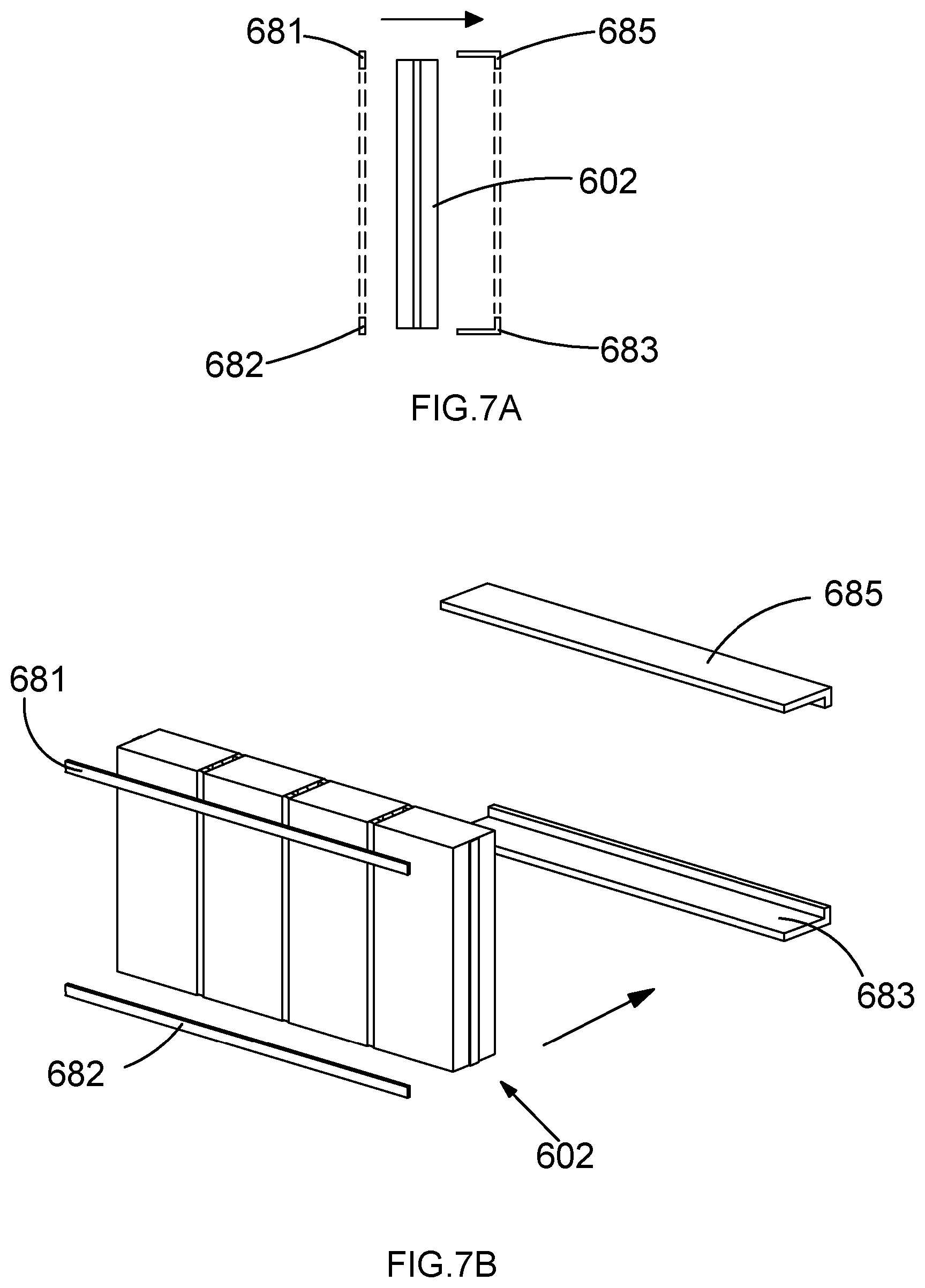
[0084] In accordance with the invention there is also provided a method of installing a glazing assembly according to those described above, the method comprising: providing a front-loading carrier for receiving the glazing assembly, the carrier comprising a frame having a height corresponding to that of the assembly, a surrounding lip on a rear side of the carrier, and a removably mounted lip on the front side of the carrier, inserting the glazing assembly into the frame from the front side when the removable lip is removed, and mounting the lip on the carrier such that the assembly is prevented from being removed from the frame.
[0085] In accordance with the invention there is also provided a method on installing a modular glazing array according to any of those described above, the method comprising: providing a front loading carrier for receiving the modular glazing array, the carrier comprising a frame having a size and shape corresponding to the height of the array, a surrounding lip on a rear side of the carrier and a removably mounted lip on the front side of the carrier, inserting the array into the frame on the front side when the removable lip is removed, and mounting the lip on the carrier such that the array is prevented from being removed from the frame.
[0086] In these methods of installation, the carrier, or the frame thereof, may have a size and shape corresponding to the width, and more generally the dimensions or perimeter, of the array. These installation methods provide the advantage that each structural array or assembly may be installed more rapidly by way of inserting the assembly or array into the frame in a front-loading manner, that is in a direction perpendicular to the primary plane of the panel or the plane defined by the frame. The glazing may then be held in place by affixing the removable lip so as to prevent further movement of the glazing in this direction once it has been installed.
BRIEF DESCRIPTION OF THE DRAWINGS
[0087] Examples for the present invention will now be described, with reference to the accompanying drawings, wherein like reference numerals indicate like features, and in which:
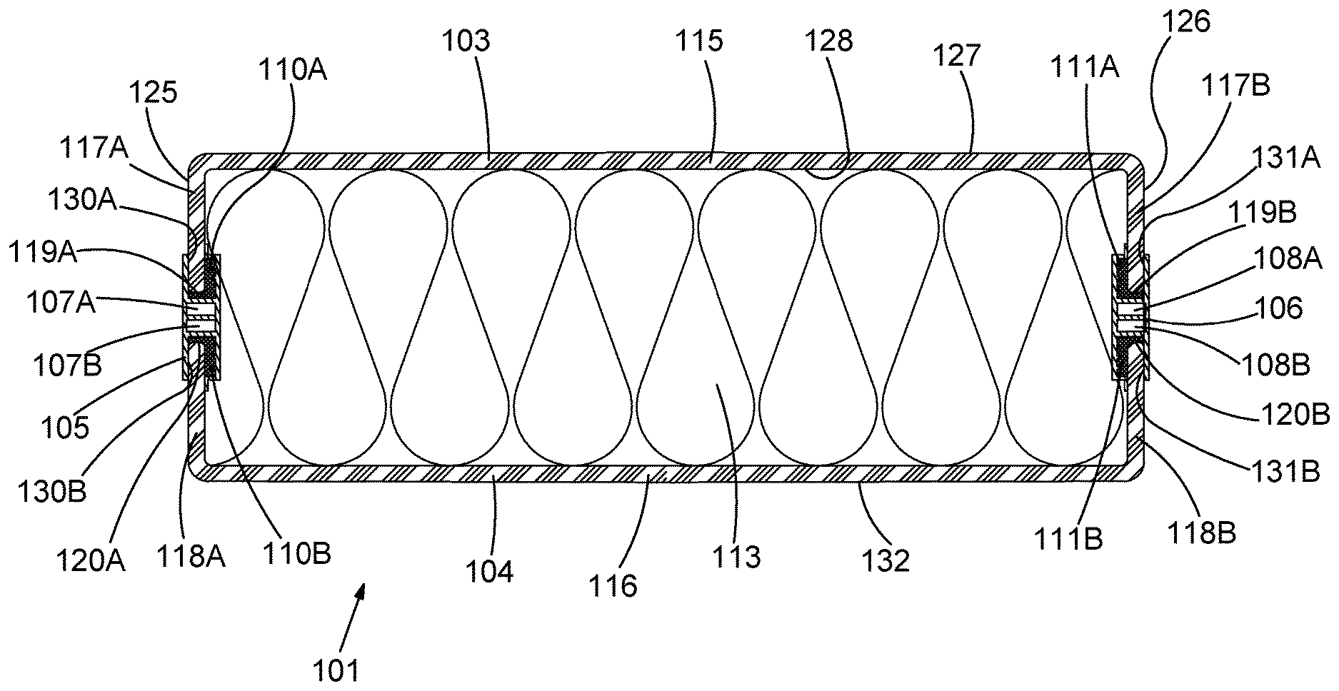
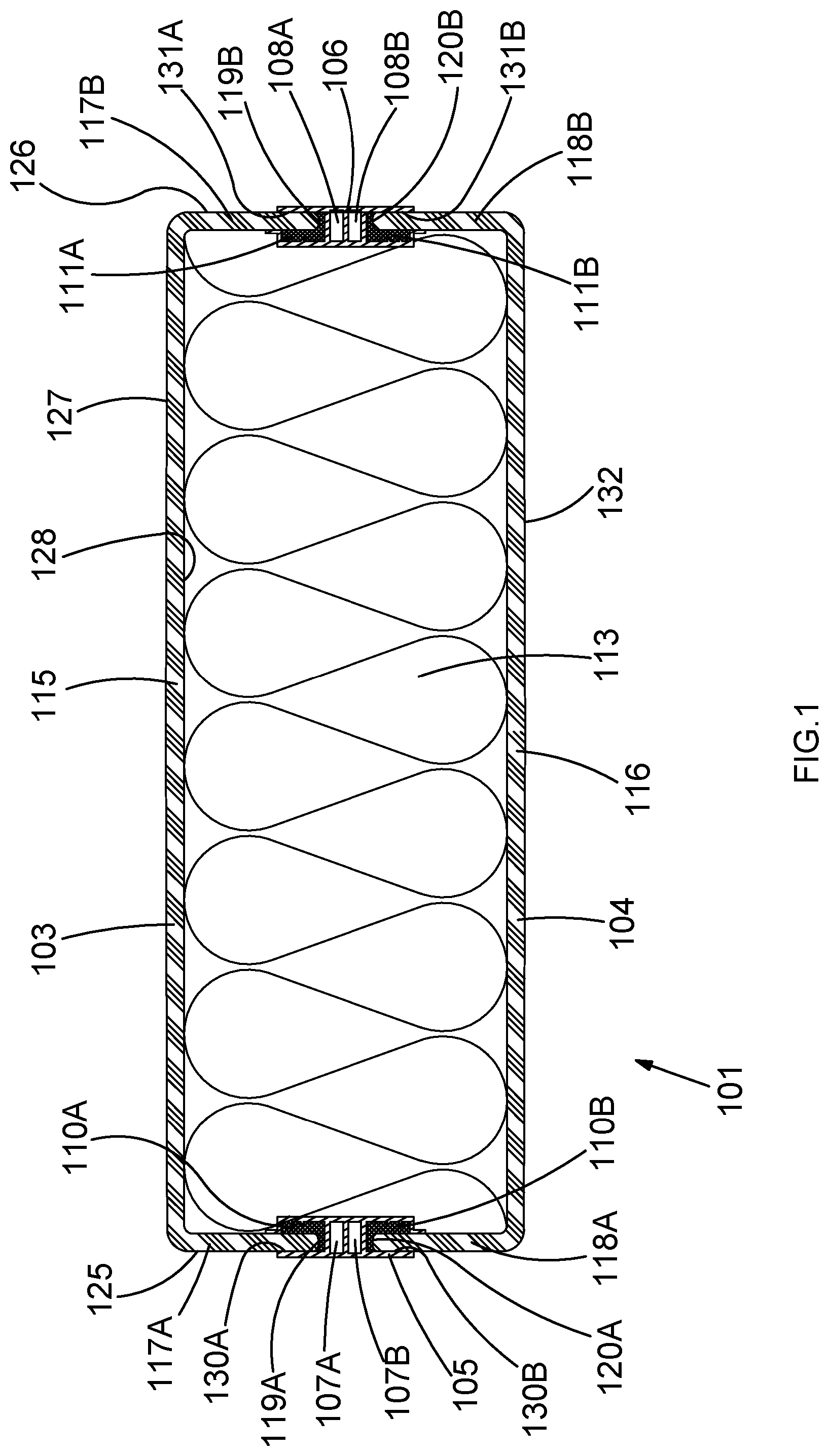
[0088] FIG. 1 is a cross section of an example glazing assembly according to the invention;
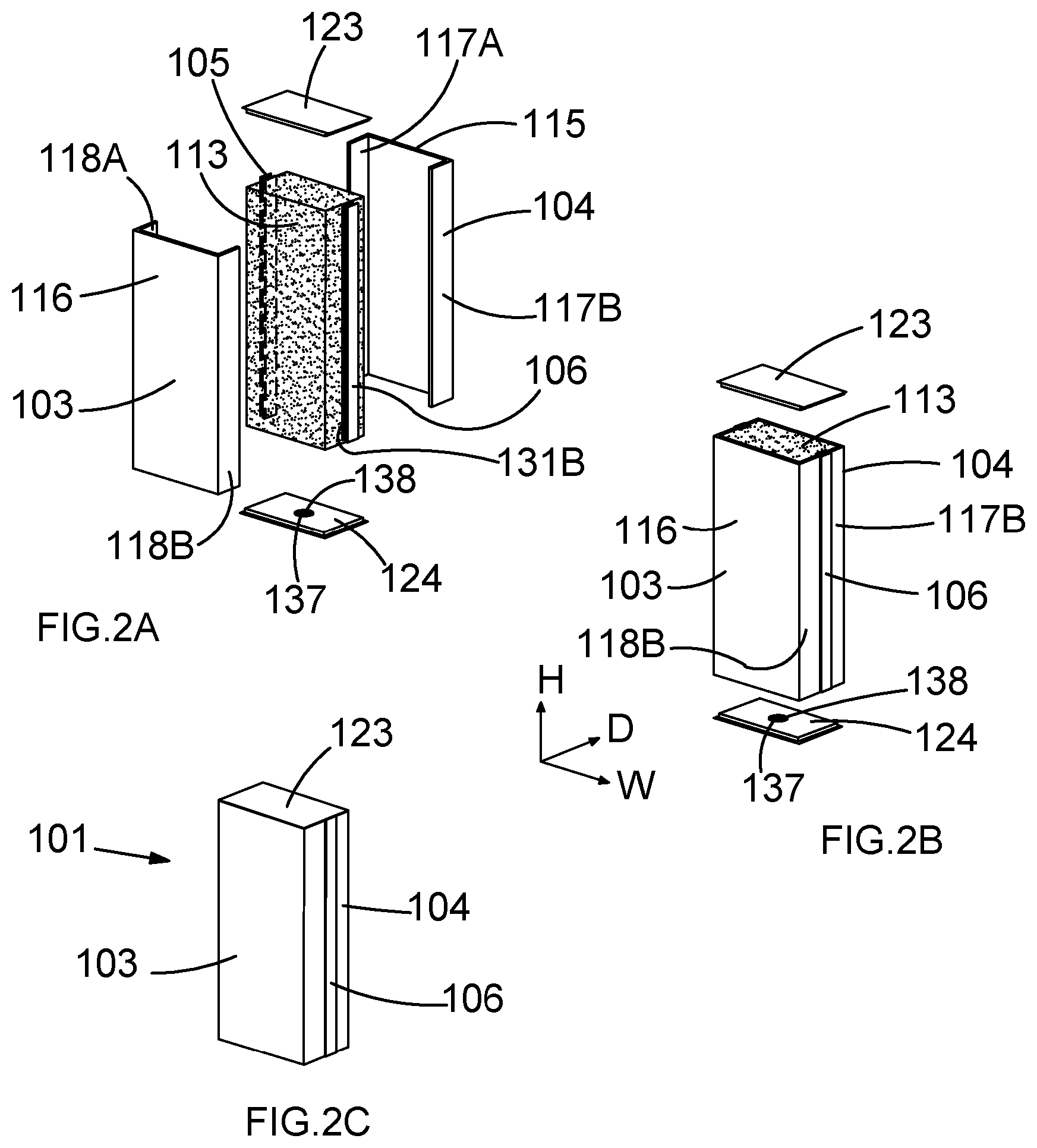
[0089] FIGS. 2A to 2C show two exploded views and a perspective view of the example glazing assembly according to the invention;
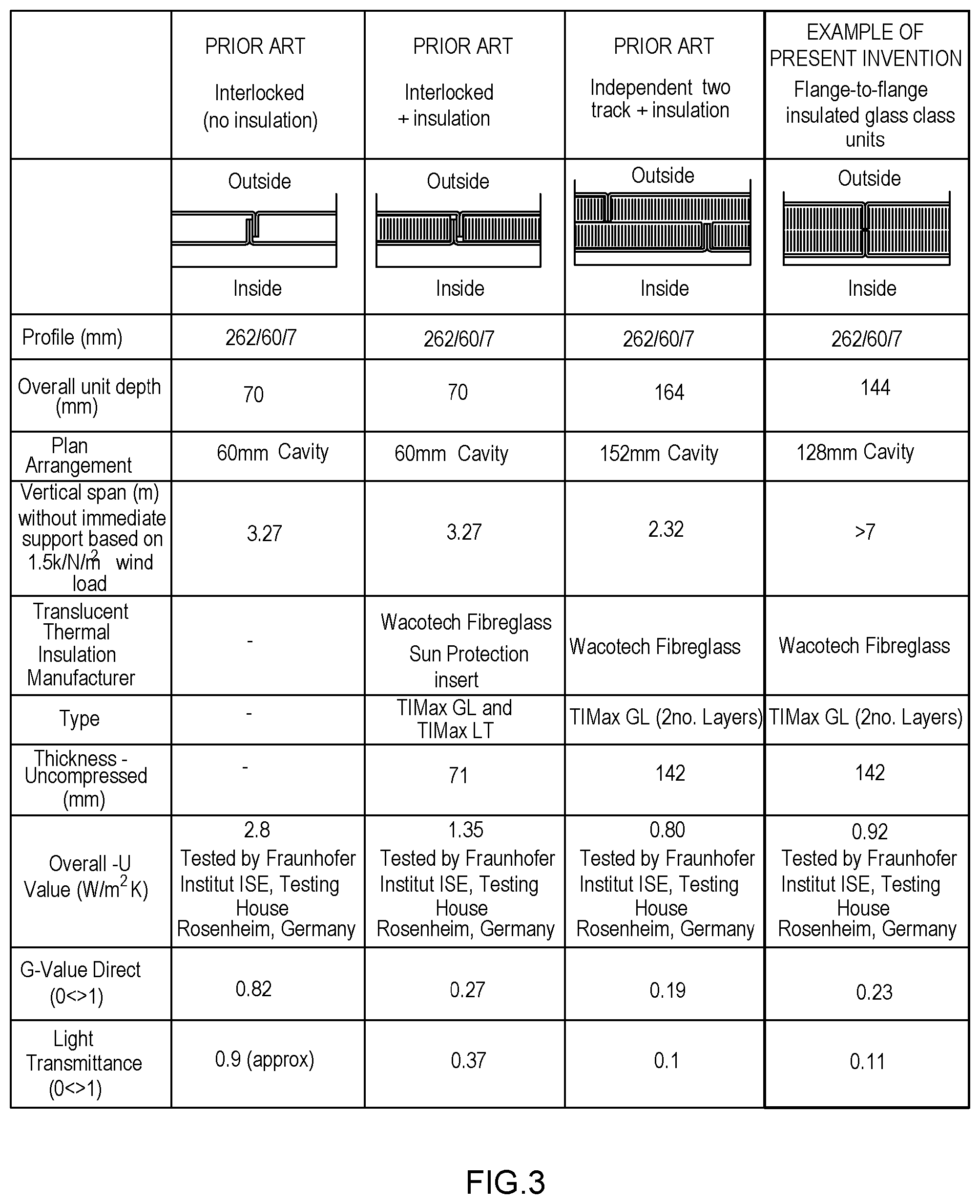
[0090] FIG. 3 is a table containing comparative data indicating various properties of the example glazing assembly according to the invention and glazing assemblies of the prior art;
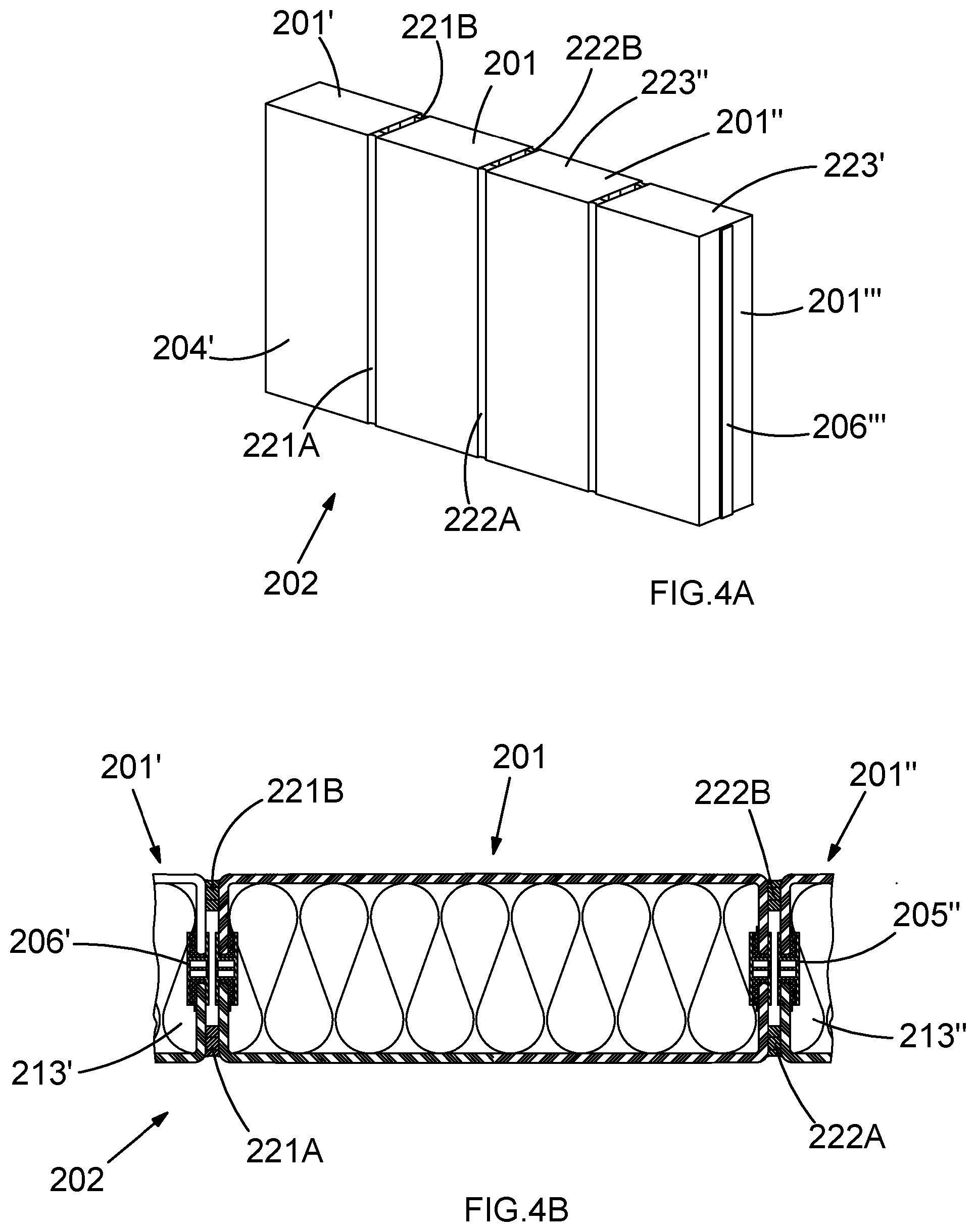
[0091] FIGS. 4A and 4B show a perspective view and a cross section of an example modular glazing array according to the invention;
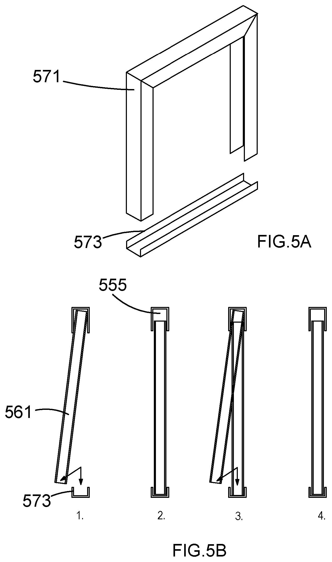
[0092] FIGS. 5A and 5B show a perspective view and a cross section, respectively, of a glazing assembly carrier and installation method according to the prior art;
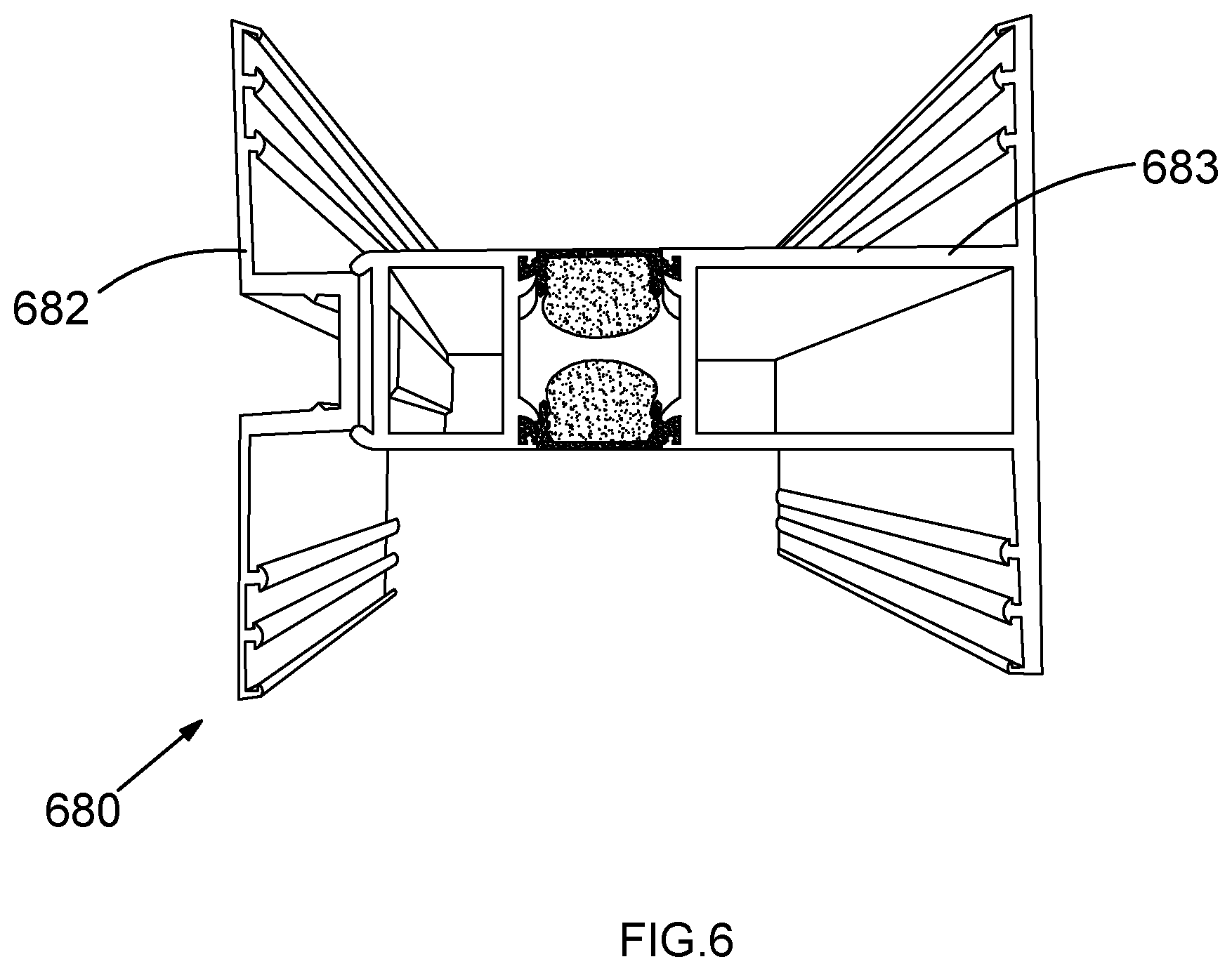
[0093] FIG. 6 is a photograph showing a cross section of part of a front loading carrier for receiving a glazing assembly or modular glazing array according to the invention;
[0094] FIGS. 7A and 7B show a cross section and a perspective view, respectively, of the installation of a modular glazing array according to the invention in a front-loading carrier;
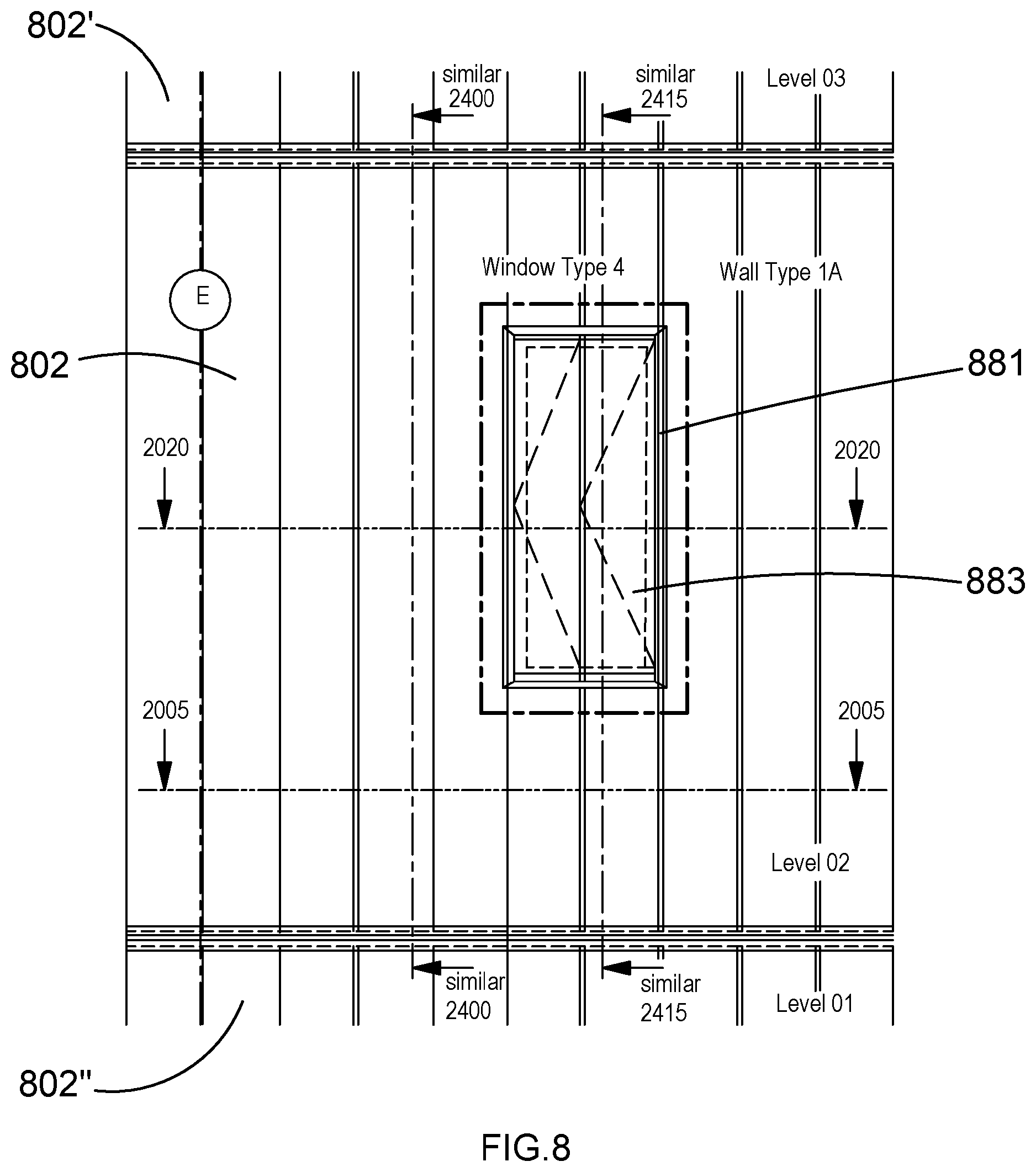
[0095] FIG. 8 is an elevation showing part of a building comprising modular glazing arrays according to the invention seen from the exterior; and
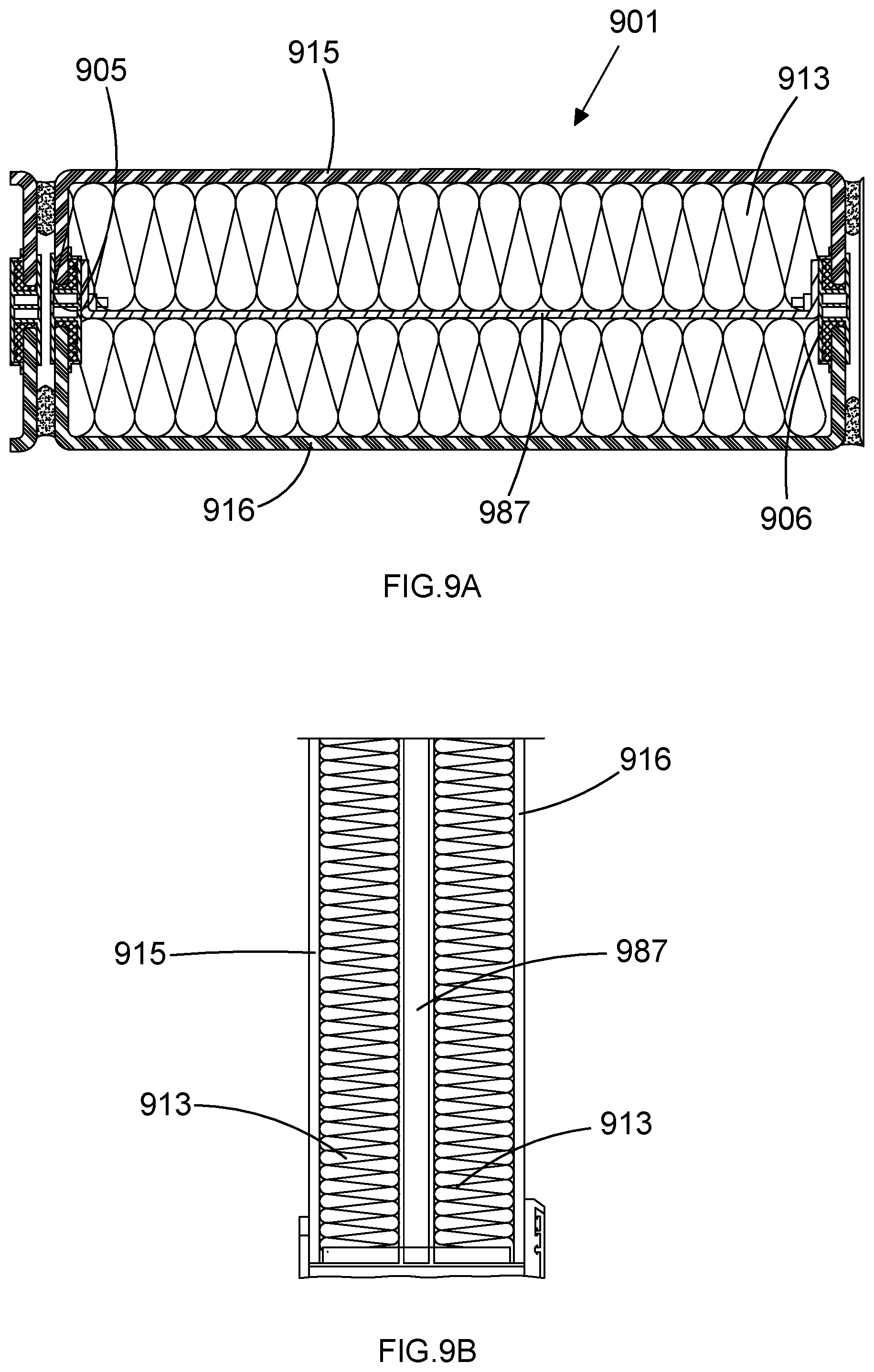
[0096] FIGS. 9A and 9B respectively show a horizontal cross section and a vertical cross section of an example modular glazing array according to the invention wherein the assembly comprises an internal protective element.
DESCRIPTION OF EMBODIMENTS
[0097] Referring to FIGS. 1 to 3, an example glazing assembly according to the invention is now described. Glazing assembly 101 comprises first and second glass U-channels 103, 104. The first U-channel member 103 comprises a planar sheet 115 with first and second perpendicular flanges 117A, 117B which project orthogonally from either side of the sheet 115 and terminate at first and second flange edges 119A, 119B, respectively. Each U-channel is made from low iron cast glass which is enamelled on the inner inside face. In the present example the project-specific width of each U-channel is 404 mm, as measured between opposite outer faces 125, 126 of first and second flanges 117A and 117B. The thickness of the glass, as measured between outer 127 and inner 128 it faces of sheet 115 is 8 mm. The glass is toughened, heat-soak tested cast glass, with enamelled frit on the inner inside face.
[0098] The tensile strength values for the toughened cast glass of the member 103 are 50 Nmm.sup.-2 for the sheet in the tension zone, and 115 Nmm.sup.-2 for a flange 117A, 117B in the tension zone.
[0099] The compressive strength of the glass is approximately 1,000 Nmm.sup.-2. This means that the applied compressive load required to shatter a 1 cm cube of the glass is 10 tonnes.
[0100] When a plane of glass is deflected, one of its faces is subjected to compression, while the other face is in tension. The resistance of the toughened glass to compressive stress is considerably greater than its resistance to tensile stress.
[0101] The resistance of the toughened glass of the member 103 to breakage on deflection is 110-200 Nmm.sup.-2. The upper end of this range corresponds to both faces of the sheet having high compressive strength imparted by the glass toughening process. The precise value is dependent upon the thickness, edgework, holes, and notches which may be applied to the member in different variations.
[0102] By contrast, the equivalent resistance value for annealed glass is in the order of 40 Nmm.sup.-2.
[0103] Likewise, the second U-channel member 104 is formed from toughened glass, and comprises a central, planar sheet 116 and perpendicular, opposing flanges on either side 118A, 118B. The two U-channels are placed in a flange-to-flange arrangement wherein the edges 119A, 20A of first flanges 117A, 118A of the first and second member 103, 104 are opposing and aligned with each other.
[0104] Similarly, the edges 119B, 120B of second flanges 117B, 118B of the first and second member 103, 104 are also aligned and opposing one another. The first and second U-channels are bonded together by first and second connectors 105, 106. The first connector 105 comprises first and second channels 130A, 130B adapted to receive an edge portion of a U-channel flange. The first and second U-channels are held together by the first and second flanges 117A, 117B of first member 103 being held within the first channels 130A, 131A and first and second flanges 118A, 118B of the second member 104 being held within second channels 130B, 131 B, of the first and second connectors 105, 106, respectively.
[0105] Each connector 105, 106, comprises a fibre-reinforced polyamide thermal extrusion. The polyamide extrusion connector 105, 106 is a TECATHERM 66 GF thermally insulating profile section, comprising polyamide 66 with 25.0 plus or minus 2.5% by weight glass fibres. This may provide a strength of greater than or equal to 110 MPa, a modulus of elasticity in tension of greater than or equal to 6000 MPa, and a thermal conductivity of 0.28 W/m.sup.2K, according to testing standards DIN 53455, 53457, and 52612 respectively. Each bonded flange is held in place with a connector by a respective portion of adhesive 110A, 110B, 111A, 111B, which comprises Dow Corning 993 white structural silicone. Thus the two U-channels are unitised by bonding the flanges into these double-sided bespoke polyamide extrusions 105, 106.
[0106] Empirical tests have shown the effective area moment of inertia of the assembly of the present example to be 420 cm.sup.4. Therefore, a 300% increase in the area moment of inertia is provided with respect to the comparative assembly comprising rubber connectors mentioned above.
[0107] The colour of the polyamide extrusion 105, 106 is refracted through the flange of the U-channel profiles 103, 104. Therefore, the colour of the extrusions should be selected appropriately.
[0108] The overall depth of the assembly, that is between outer faces 127 and 132 of the first and second sheet 115, 116 is 144 mm. The additional depth provided by this arrangement significantly increases the vertical span achievable by the
[0109] U-channel, because the two U-channels are structurally bonded and act in unison. With a typical wind load requirement of 1.5 kN/m.sup.2, a single cast glass U-channel 262 mm wide will achieve a vertical span in excess of 7 m [7 m is generally the longest length of U-channel manufactured within acceptable tolerances, therefore the designer has more freedom with the width of a single U-channel, considering that the wider the U-channel, the shorter the achievable vertical span]. The volume between the two members is filled with Wacotech TIMax GL translucent glass fibre insulation 113. The insulation is installed in the factory at the same time as the bonding of the flanges together. By doing this off-site, that is prior to the delivery of the glazing assembly to the site where it is to be installed, the amount of contamination is minimised during the encapsulation process.
[0110] The assembly process is illustrated at several stages in FIGS. 2A to 2C. The exploded view shown in FIG. 2A contains the elements previously described, as well as Forex thermoformed top and bottom caps 123, 124, in a disassembled state. In FIG. 2B, the first and second U-channels 103, 104 have been bonded together with first and second connectors 105, 106, so as to partially enclose glass fibre insulation 113. This optically white translucent insulation is hung and held at the top in slight compression. This provides the assembly with thermal performance and light transmission levels which provide a quality of diffused "white" natural light to the interior of a building in which the glazing is installed. The translucent envelope also offers users privacy, and alleviates issues of overlooking that are associated with densely populated, urban environments.
[0111] The height, width, and depth axes which are used to refer to the dimensions of the assembly are indicated in the present figure by the letters H, W, and D, respectively. The relative dimensions of the assembly shown in the present figure are not to scale. Furthermore, although the edges between the flanges 117, 118 and the sheets 115, 116 are illustrated as having a sharp or defined edge, in practice these generally comprise rounded edges, owing to the nature of the casting process and the increased strength or decreased vulnerability which may be achieved by incorporating a more rounded corner to the U-channel profile.
[0112] In assembling the cast glass unit 101, when the U-channels 103, 104 have been attached together in a toe-to-toe arrangement using the two-part structural silicone (not shown) to bond the U-channels with the polyamide extrusions 105, 106, as shown in FIG. 2B, closure caps 123 and 124 are applied to the top and bottom apertures 134, 136 of the approximately rectangular tubular assembly 101. This sealing of the top and bottom edges of the unit with purpose-made thermoformed caps 123, 124 is shown in FIG. 2C. The bottom cap 124 contains a weep hole 137 including an interior insect mesh 138. This provides an outlet for condensation run-off and pressure equalisation of the unit. The resulting, complete cast glass unit 101 is able to be used with a wind load criterion in excess of 2.5 kN/m.sup.2 for a span of 4.2 m, owing to the increased structural strength provided by the toe-to-toe arrangement. This removes the need for any vertical framing or additional vertical support. Glazing assemblies with dimensions corresponding to those indicated in the final column of the table of FIG. 3 have been tested successfully for a 4.2 m vertical span under these conditions. The novel arrangement overcomes the limitations of cast glass U-channels and achieves this vertical span without intermediate support with an overall facade thickness of only 144 mm. Additionally, the structural capabilities of the glazing assembly are particularly beneficial in sections with windows and door openings. The cast glass unit is able to carry the load of a 2000 mm.times.808 mm triple glazed window unit without any additional support, rendering it an integrated cladding element. The glazing assembly structurally supports openable triple glazed windows, and openings with no additional vertical support. The unitised system is adaptable to include additional layers of security to protect against intrusion, by way of hard body impact resistance.
[0113] The assembly represents an innovation in large unitised structural, toughened U-channel cast glass elements that have been fabricated and sealed off-site and installed on-site in modules, thus maintaining quality of workmanship, especially in the silicone, while facilitating a faster on-site installation than any previous U-channel cast glass facade.
[0114] A comparison of the present example of the glazing assembly of the present invention with conventional assemblies available in the prior art is shown in the table of FIG. 3. In particular, columns 1 and 2 contain data relating to the interlocked assemblies, excluding and including interior insulation respectively, wherein U-channels are assembled together with their flanges overlapping and interlocking with one another, rather than being bonded in an edge-to-edge arrangement. The third column indicates the properties of a prior art glazing arrangement wherein two independent layers or tracks of single layer glass U-channels are provided. The final column contains test data for the presently described example of the glazing assembly according to the invention.
[0115] In view of this figure, the limitations of the prior art glazing approaches and the relative advantages now provided may be seen. Using a typical wind load requirement of 1.5 kN/m.sup.2, the interlocked arrangement achieves a vertical span of 3.27 m with 262 mm-wide toughened U-channels, or 2.94 m with 330 mm-wide toughened U-channels. This is as compared to a vertical span in excess of 7 m for the equivalent assembly when arranged according to the present arrangement.
[0116] The interlocking assembly also suffers from thermal insulation limitations, as can be seen from the higher U-values achieved by the assemblies illustrated in the first two columns when compared with that of the present arrangement as shown in the final column. The lack of thermal breaks or isolation with the interlocking assembly, in addition to the requirement of this type of assembly for horizontal and vertical carriers which may themselves conduct heat, makes the channels susceptible to condensation. By providing weep holes in the carrier to drain condensation, there would be a risk of insect penetration introduced, which may be difficult to address owing to the lack of access for cleaning the interior of the assemblies.
[0117] With regard to wind suction, the interlocked assembly is typically supported by top and bottom horizontal carriers. Additional wind anchors or intermediate support to the vertical spans may be used, however these are limited. This is especially the case if the interlocked system is to be used in areas of high wind loads, or at significant height, as the mid-span is held in place only by weathering silicone joints.
[0118] The edges of the U-channels are, as is the case with most glass, and in particular toughened glass, the most susceptible to damage which results in total failure. The interlocked system provides no protection in the case of an impact as the deflection causes the glass of the outer face of one flange to impact or contact the flange of an adjacent U-channel, which may cause failure. The present arrangement alleviates the risk of such impact-induced failure, owing to the first member 103 being separated from, and therefore not contacting upon an impact to one of the sheets 115, for instance, the second member 104.
[0119] In architectural applications, it is preferable for width-to-height ratios of approximately 1 to 10 to be achieved, and this is possible with cast glass U-channel units. Therefore, when the requirement is for a vertical span of 4.2 m, corresponding to a typical floor-to-floor distance on a building, a 262 mm or 330 mm-wide U-channel is not preferable, as these widths are too narrow to achieve the desired proportions. The present arrangement facilitates the creation of cast glass U-channel units that correspond to this desired aspect ratio. Furthermore, by providing a U-channel assembly with increased width, the number of joints between adjacent U-channels arranged side-by-side on a facade, for example is reduced.
[0120] Cast glass is not optically clear. However, glass fibre insulation may still be visible through the glass of a U-channel when pressed up against its interior surface. In order to achieve a light-diffusing finish, and render these fibres invisible to an exterior viewer, various finishes may be applied to the inside face of the U-channels which manufacturers of the U-channel offer.
[0121] The outside face 132 of sheet 116 is provided with a plurality of millimetre-scale grooves in a repeating pattern. The grooves run the entire height of the sheet 116, and are aligned with the height axis. Thus the assembly is suitable for installation in a building with the second member 104 as the outer, or exterior-facing member, such that the grooves are aligned vertically and can provide a self-cleaning function.
[0122] The interior-facing sheet 103 has a roughened, `solar` surface profile applied to the outer face 127. This presents to building occupants, a surface texture which diffuses light passing through the sheet 103 and renders the fibres of insulation 113 indistinguishable or invisible, and upon which it is possible to write and draw using marking pens.
[0123] The nature of the interlocked assembly, and other assemblies, limits the geometry that can be achieved with a U-channel envelope. The nature of the installation of the assemblies in a linear arrangement or on a single curve with limited radius and the interlocked arrangement are not suited for windows and openings if they are not structurally independent from the U-channels. These elements shall require vertical framing to bridge the gap between the two systems. The structural capability provided by the present arrangement alleviates this issue.
[0124] The comparison shown in FIG. 3, which assumes one particular insulation material and one type and width of U-channel glass, clearly illustrates the advantageous properties provided by the phasing assembly of the present example glazing assembly. The results show that the thermal performance of the glazing envelope, its ability to diffusively transfer daylight and avoid non-beneficial solar gains are critical to helping to achieve compliance with current UK regulations. It also means that the thermal efficiency and comfort of occupants of a building is achieved for those in close proximity to the building envelope without requiring perimeter heating.
[0125] The light transmission at 11% provides a diffused "white" natural illumination to the interior. In the present example, an illuminance level of 300 lux may be achieved given an overcast sky, at a distance of 4 m back from the interior of a facade comprising the example glazing assembly. The present example glazing assembly removes the glare, and strong, dazzling light to which occupants of buildings utilising prior art glazing assemblies may be subjected. This is particularly beneficial in relation to occupants viewing computer displays. The translucent envelope additionally offers privacy and alleviates overlooking issues associated with inner city densities.
[0126] An example modular glazing array comprising a plurality of glazing assemblies according to the invention is shown in FIGS. 4A and 4B. These drawings show a perspective and cross section view, respectively. The array 202 comprises four glazing assemblies 201, 201', 201'' etc., each of which is similar to the example assembly described above. In the present example, five assemblies are shown as being attached in a linear arrangement such that the sheets 216, 216', 216'' etc. are substantially coplanar. It is additionally envisaged that alternative arrays may be provided, which may contain different numbers of constituent assemblies, and which may be arranged so as to be aligned in curved as well as straight alignment.
[0127] Nominally 9 mm-wide weather silicone joints 221A, 221B, 222A, 222B are disposed between adjacent cast glass assemblies along the outer edges of the gaps between them. The joints can have variable geometry and can vary between 5 mm and 25 mm wide to enable arrays having curved geometries.
[0128] Attaching the structural cast glass assemblies together to form wider array panels prior to installation in a building allows the rate of installation to be improved. This is particularly apparent with reference to conventional installation methods for U-channel glazing according to the prior art. Such prior art installation methods are illustrated in FIGS. 5A and 5B. These conventional techniques for on-site installation of U-channels is a slow and usually manual process, which involves handheld suckers and a sliding procedure. This involves offering a U-channel 561 into an oversized horizontal top frame 571 and subsequently lowering the U-channel into a bottom horizontal carrier 573. This process is shown in four sequential stages in FIG. 5B. The glazing is then siliconed to provide a weather seal. This technique for manual installation is incompatible with large-scale installations and those at high levels, as well as where site labour costs are high. It can also result in limited overall thermal performance caused by the installation tolerance voids (555) in the top frame, which must be maintained for glass replacement. The manual handling and installation of the U-channels, and the amount of on-site siliconing, make the system susceptible to construction site and insect contamination, inclement weather, as well as to irregular workmanship and quality issues.
[0129] In order to further benefit from the modularised assemblies and arrays of the present invention, one must move entirely away from the conventional "sliding" installation procedure illustrated in FIG. 5B, and the typical aluminium framing elements shown in FIG. 5A. FIG. 6 shows a thermally broken extruded aluminium profile designed to act as a horizontal carrier for a method of installation according to the invention. The carrier 680 comprises a removable front capping plate 682. The presence of this feature allows individual U-channels and cast glass units to be installed by way of being offered horizontally, rather than being slid into a top carrier and then dropped into the bottom carrier 683. Thus the need for the top carrier to comprise a large void to tolerate the upward and downward sliding movement of the glazing assembly is removed.
[0130] The installation process is illustrated in FIGS. 7A and 7B, which show a cross section and a perspective view of the carrier, respectively. Glazing array 602 is offered up horizontally, in the direction indicated by the arrow, so as to be received by a carrier, and to be held vertically between top and bottom 685, 683 elements of the carrier frame. Removable capping plates 681, 682 may then be affixed to the carrier frame, so as to hold the array 602 in place horizontally.
[0131] In the present example, pre-panelised assembly off-site is facilitated. Individual cast glass units according to the invention may be pre-fabricated, and four cast glass units are assembled together into an array module. The total size of this module is 1.7 m wide.times.4.2 m high, including all of the vertical weathering silicone joints. This is advantageous with respect to windows and other openings being included. Such additional or inset elements may also be included, installed, sealed, and wired off-site. Wiring, for instance, may be present in building management system window contacts and power for controlling external motorised louvers.
[0132] The modularised assembly represents the first time large unitised U-channel cast glass elements have been fabricated and sealed off-site and installed in on-site modules, maintaining the quality of workmanship, in particular in the silicone, and facilitating a rate of installation that is faster than that achievable with any previous U-channel cast glass facade.
[0133] FIG. 8 depicts the exterior of a building in which multiple modular arrays 802, 802', 802'' of glazing assemblies are installed vertically above one another. The central one of the three illustrated arrays 802 comprises a rectangular aperture 881. The aperture is formed by cutting through the entire depth of the modularised array. Owing to the structural strength of each assembly, and the resultant structural capacity of the array derived from this, a double- or triple-glazed, openable window unit 883 is held within the aperture, such that the weight of the unit 883 is entirely supported by the array 802.
[0134] A further example modular glazing array comprising a plurality of glazing assemblies according to the invention, similar to that shown in FIG. 4B is shown in FIGS. 9A and 9B. These drawings show a horizontal and vertical cross section view through the centre of the array, respectively.
[0135] The present example contains a glazing assembly 901 that includes an internal protective element 987 disposed in the volume between the first and second toughened glass members 915, 916. The element has the form of a polycarbonate insert that is affixed to the connector portions 905 of the assembly. This layer of impact-resistant material that is provided between the layers or volumes of insulating material 913 achieves intruder resistance in accordance with Clause H11/640. Resistance testing for conformance with this standard is defined in relation to ground-level glazing assemblies, and is carried out in accordance with BSEN356 and achieves P1A resistance class standard.
* * * * *
D00000
D00001
D00002
D00003
D00004
D00005
D00006
D00007
D00008
D00009
XML
uspto.report is an independent third-party trademark research tool that is not affiliated, endorsed, or sponsored by the United States Patent and Trademark Office (USPTO) or any other governmental organization. The information provided by uspto.report is based on publicly available data at the time of writing and is intended for informational purposes only.
While we strive to provide accurate and up-to-date information, we do not guarantee the accuracy, completeness, reliability, or suitability of the information displayed on this site. The use of this site is at your own risk. Any reliance you place on such information is therefore strictly at your own risk.
All official trademark data, including owner information, should be verified by visiting the official USPTO website at www.uspto.gov. This site is not intended to replace professional legal advice and should not be used as a substitute for consulting with a legal professional who is knowledgeable about trademark law.