Vehicle Lamp
Kitazawa; Tatsuma
U.S. patent application number 16/531632 was filed with the patent office on 2020-02-06 for vehicle lamp. This patent application is currently assigned to KOITO MANUFACTURING CO., LTD.. The applicant listed for this patent is KOITO MANUFACTURING CO., LTD.. Invention is credited to Tatsuma Kitazawa.
| Application Number | 20200039420 16/531632 |
| Document ID | / |
| Family ID | 69168564 |
| Filed Date | 2020-02-06 |


| United States Patent Application | 20200039420 |
| Kind Code | A1 |
| Kitazawa; Tatsuma | February 6, 2020 |
VEHICLE LAMP
Abstract
A vehicle lamp includes: a light distribution controller configured to generate a light distribution pattern including a shaded portion in which a margin region is added around a snow particle; and a variable light distribution lamp capable of generating a beam having an intensity distribution corresponding to the light distribution pattern. And at least one of a size and a shape of the margin region is variable.
| Inventors: | Kitazawa; Tatsuma; (Shizuoka-shi, JP) | ||||||||||
| Applicant: |
|
||||||||||
|---|---|---|---|---|---|---|---|---|---|---|---|
| Assignee: | KOITO MANUFACTURING CO.,
LTD. Tokyo JP |
||||||||||
| Family ID: | 69168564 | ||||||||||
| Appl. No.: | 16/531632 | ||||||||||
| Filed: | August 5, 2019 |
| Current U.S. Class: | 1/1 |
| Current CPC Class: | F21W 2102/17 20180101; B60Q 2300/41 20130101; B60Q 2300/056 20130101; B60Q 2300/312 20130101; B60Q 2300/054 20130101; B60Q 1/143 20130101; B60Q 2300/42 20130101; F21S 41/65 20180101; B60Q 2300/45 20130101 |
| International Class: | B60Q 1/14 20060101 B60Q001/14; F21S 41/65 20060101 F21S041/65 |
Foreign Application Data
| Date | Code | Application Number |
|---|---|---|
| Aug 6, 2018 | JP | 2018-147921 |
| Aug 9, 2018 | JP | 2018-150097 |
Claims
1. A vehicle lamp comprising: a light distribution controller configured to generate a light distribution pattern including a shaded portion in which a margin region is added around a snow particle; and a variable light distribution lamp capable of generating a beam having an intensity distribution corresponding to the light distribution pattern, wherein at least one of a size and a shape of the margin region is variable.
2. The vehicle lamp according to claim 1, wherein at least one of the size and the shape of the margin region corresponds to a position of the snow particle.
3. The vehicle lamp according to claim 2, wherein the margin region becomes smaller in a case where a position of the snow particle becomes higher, and becomes larger in a case the position of the snow particle becomes lower.
4. The vehicle lamp according to claim 2, wherein the margin region becomes larger in a case where the snow particle becomes farther from a vanishing point.
5. The vehicle lamp according to claim 1, wherein a vehicle speed is reflected in the at least one of the size and the shape of the margin region.
6. The vehicle lamp according to claim 2, wherein a vehicle speed is reflected in the at least one of the size and the shape of the margin region.
7. The vehicle lamp according to claim 3, wherein a vehicle speed is reflected in the at least one of the size and the shape of the margin region.
8. The vehicle lamp according to claim 4, wherein a vehicle speed is reflected in the at least one of the size and the shape of the margin region.
9. The vehicle lamp according to claim 1, wherein an output of a raindrop sensor is reflected in the at least one of the size and the shape of the margin region.
10. The vehicle lamp according to claim 2, wherein an output of a raindrop sensor is reflected in the at least one of the size and the shape of the margin region.
11. The vehicle lamp according to claim 3, wherein an output of a raindrop sensor is reflected in the at least one of the size and the shape of the margin region.
12. The vehicle lamp according to claim 4, wherein an output of a raindrop sensor is reflected in the at least one of the size and the shape of the margin region.
13. The vehicle lamp according to claim 5, wherein an output of a raindrop sensor is reflected in the at least one of the size and the shape of the margin region.
14. The vehicle lamp according to claim 6, wherein an output of a raindrop sensor is reflected in the at least one of the size and the shape of the margin region.
15. The vehicle lamp according to claim 7, wherein an output of a raindrop sensor is reflected in the at least one of the size and the shape of the margin region.
16. The vehicle lamp according to claim 8, wherein an output of a raindrop sensor is reflected in the at least one of the size and the shape of the margin region.
17. The vehicle lamp according to claim 1, wherein the light distribution controller is configured to detect the snow particle based on an image of reflected light obtained depending on a probe light irradiated by an infrared illumination device, the image being captured by an infrared camera.
Description
CROSS-REFERENCE TO RELATED APPLICATIONS
[0001] This application is based on and claims priority under 35 USC 119 from Japanese Patent Applications No. 2018-147921 filed on Aug. 6, 2018 and No. 2018-150097 filed on Aug. 9, 2018, the contents of which are incorporated herein by reference.
TECHNICAL FIELD
[0002] The present invention relates to a vehicle lamp.
BACKGROUND
[0003] Vehicle lamps are important for traveling safely during nighttime or in a tunnel. When a driver prioritize visibility thereof and illuminate a wide range in front of a vehicle, there is a problem that glare is given to a driver of a preceding vehicle or an oncoming vehicle existing in front of the vehicle (hereinafter, referred to as a front vehicle) or a pedestrian.
[0004] In recent years, an adaptive driving beam (ADB) technique, which dynamically and adaptively controls a light distribution pattern based on a state around a vehicle, is proposed. The ADB technology detects existence of the front vehicle or the pedestrian, and reduces the glare given to the driver of the front vehicle or to the pedestrian by, for example, dimming or extinguishing lighting in a region corresponding to the front vehicle or the pedestrian.
[0005] When a head lamp is lighted during snowfall (or rainfall), there is a problem that beams are reflected by snow particles and give glare to a driver, making it difficult for the driver to view forward. In order to solve this problem, the present inventors studied control of detecting snow particles and shading surrounding regions thereof.
[0006] In a system capable of performing ultra-high-speed control, it is possible to make shaded regions as close as possible to sizes of the snow particles. However, such a system is very expensive and impractical. Therefore, in a practical system, a range of shaded portions is necessarily expanded to include surrounding regions of the snow particles. If the shaded portions are large, since beams are not irradiated onto objects that overlap the snow particles behind the snow particles, there is a problem that visibility is reduced.
[0007] The present invention is made in view of this circumstance, and an exemplary object of such an aspect is to improve visibility of a front of a vehicle during snowfall.
SUMMARY
[0008] An aspect of the present invention relates to a vehicle lamp. The vehicle lamp includes: a light distribution controller configured to generate a light distribution pattern including shaded portions in which margin regions are added around snow particles; and a variable light distribution lamp capable of generating a beam having an intensity distribution corresponding to the light distribution pattern. At least one of sizes and shapes of the margin regions are variable.
[0009] Any combinations of constituting elements described above, and implementations of the invention in form of methods, devices, systems, and the like are also effective as aspects of the present invention.
[0010] According to the present invention, the visibility of the front of the vehicle during snowfall can be improved.
BRIEF DESCRIPTION OF DRAWINGS
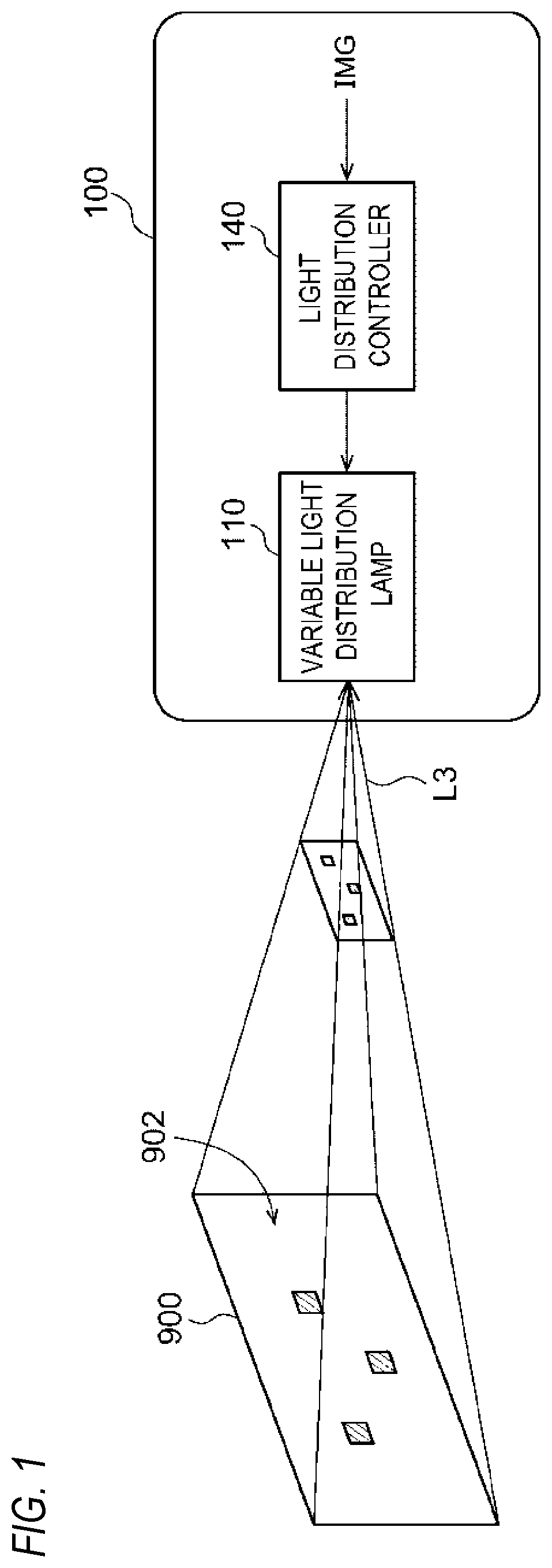
[0011] FIG. 1 is a block diagram of a vehicle lamp according to an embodiment;
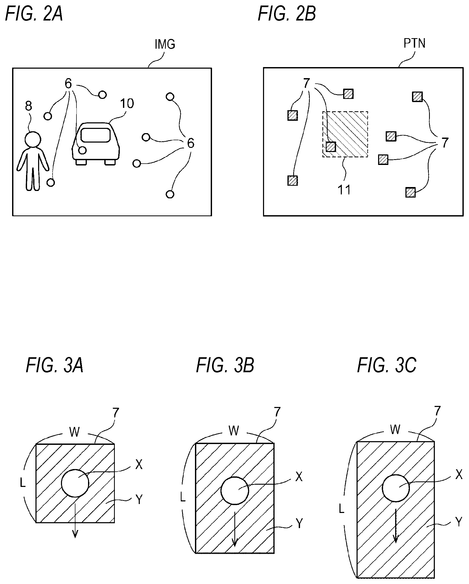
[0012] FIG. 2A illustrates a camera image IMG;
[0013] FIG. 2B illustrates a light distribution pattern PTN;
[0014] FIG. 3A is an enlarged view of a shaded portion;
[0015] FIG. 3B is an enlarged view of a shaded portion;
[0016] FIG. 3C is an enlarged view of a shaded portion;
[0017] FIG. 4 is a flowchart describing control of margin regions based on positions;
[0018] FIG. 5 is a photograph taken from a traveling vehicle during snowfall;
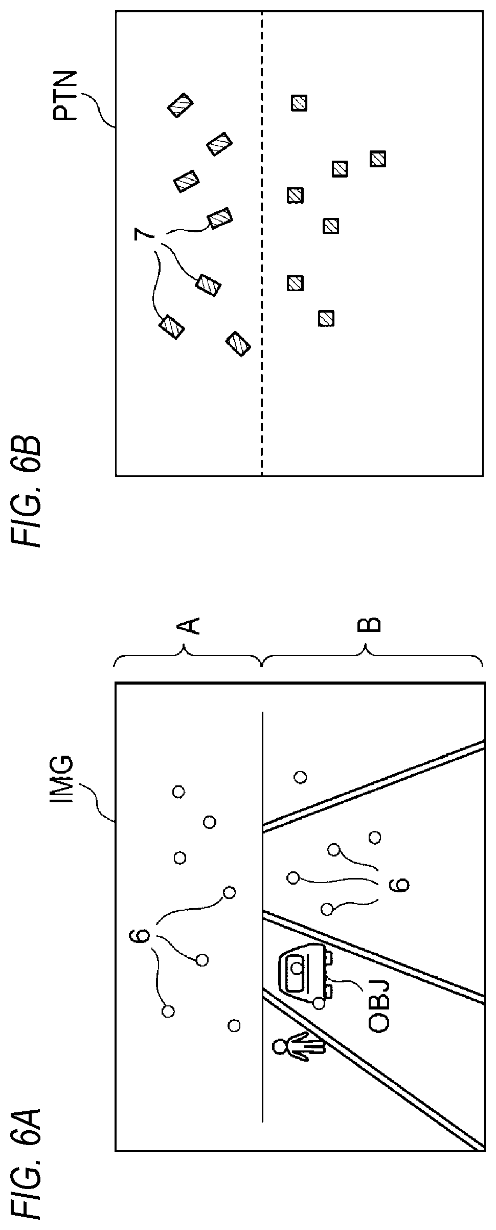
[0019] FIG. 6A illustrates a camera image IMG;
[0020] FIG. 6B illustrates a light distribution pattern PTN; and
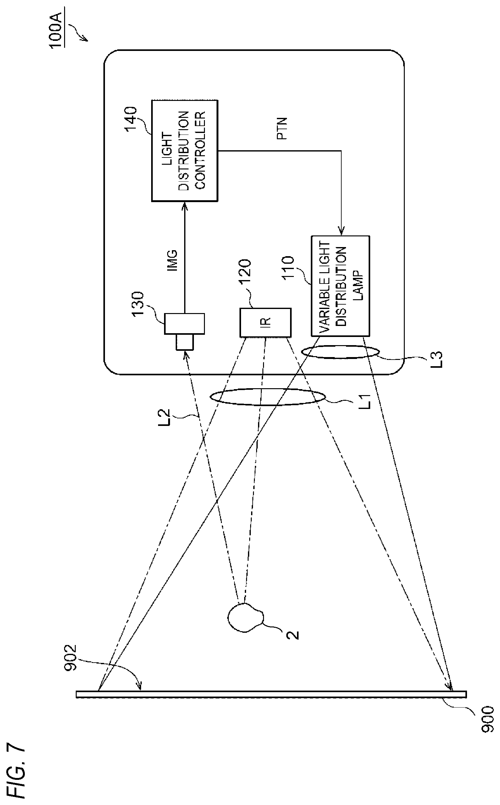
[0021] FIG. 7 is a block diagram of a vehicle lamp according to an example.
DETAILED DESCRIPTION
Overview of Embodiment
[0022] A vehicle lamp according to an embodiment disclosed in the present specification includes: a light distribution controller, configured to generate a light distribution pattern including shaded portions in which margin regions are added around snow particles; and a variable light distribution lamp, which is capable of generating a beam having an intensity distribution corresponding to the light distribution pattern. In such a lamp, if the margin regions are large, a capability to follow the snow particles is improved, but surrounding regions of the snow particles are darkened and visibility is thus reduced. On the contrary, if the margin regions are small, the visibility is improved since beams can be irradiated around the snow particles, but the capability to follow the snow particles is reduced. Therefore, by controlling the margin regions according to situations, a balance can be achieved between the capability to follow and the visibility.
[0023] At least one of sizes and shapes of the margin regions may be set according to positions of the snow particles. Trajectories of the snow particles during traveling move radially from a vanishing point. Apparent lengths of the trajectories of the snow particles (amounts of movement per unit time) become longer when the snow particles become closer to a given vehicle, that is, farther from the vanishing point. Therefore, the margin regions may become larger in a case where the snow particles become farther from the vanishing point. Accordingly, a capability to follow snow particles that are close to the given vehicle can be improved.
[0024] Since snow falls from a sky, the vanishing point of the snow particles is located above an image. Therefore, the sizes of the margin regions may become smaller in a case where positions of the snow particles become higher and may become larger in a case where the positions of the snow particles become lower. Accordingly, control can be simplified.
[0025] The sizes and shapes of the margin regions may reflect a vehicle speed. Accordingly, the capability to follow the snow particles can be improved during high-speed traveling, and the visibility can be improved during low-speed traveling or parking.
[0026] The sizes and shapes of the margin regions may reflect an output of a raindrop sensor. It is difficult to accurately detect sizes of the snow particles. Therefore, it can be assumed that there is a correlation between the output of the raindrop sensor and the sizes of the snow particles, and the sizes of the snow particles can be reflected by sizes of shaded portions through adjusting the margin regions.
[0027] In a range in which an object to be noticed (hereinafter, referred to as a noticed object) is present, such as a preceding vehicle, an oncoming vehicle, or a pedestrian, it may be preferable to prioritize visibility of the noticed object instead of the capability to follow the snow particles. On the other hand, in a range in which the noticed object is absent, for example, a background is the sky, or in a range in which the object is located far away, there is no problem in giving priority to the capability to follow. Therefore, the sizes of the margin regions may be reduced in the range in which the noticed object is present.
Embodiment
[0028] The above is an overview of the vehicle lamp. Hereinafter, the present invention will be described based on a preferred embodiment with reference to the drawings. The embodiment is not intended to limit the invention and all the features and combinations thereof described in the embodiment are not necessarily essential to the invention. The same or equivalent components, members, and processes shown in the drawings are denoted by the same reference numerals, and a repetitive description thereof will be omitted. In addition, the scale and shape of each part shown in each of the drawings are set for convenience to simplify the description, and are not to be interpreted as limitations unless otherwise specified. When the terms "first", "second" and the like are used in the present specification and claims, the terms are not intended to represent any order or importance, and are intended to distinguish one configuration from another.
[0029] FIG. 1 is a block diagram of the vehicle lamp according to the embodiment. The vehicle lamp 100 includes a variable light distribution lamp 110 and a light distribution controller 140.
[0030] The variable light distribution lamp 110 is a white light source, which receives data indicating a light distribution pattern PTN from the light distribution controller 140, emits a beam L3 having an intensity distribution (beam profile) corresponding to the light distribution pattern PTN, and forms an illuminance distribution corresponding to the light distribution pattern PTN in front of the vehicle. A configuration of the variable light distribution lamp 110 is not particularly limited, and may include, for example, a semiconductor light source, such as a laser diode (LD) or a light emitting diode (LED), and a lighting circuit for driving and lighting the semiconductor light source. The variable light distribution lamp 110 may include a matrix-type pattern forming device, such as a digital mirror device (DMD) or a liquid crystal device, so as to form the illuminance distribution corresponding to the light distribution pattern PTN. The variable light distribution lamp 110 has a resolution enough to shade only the portions of the snow particles.
[0031] The light distribution controller 140 dynamically and adaptively controls the light distribution pattern PTN supplied to the light distribution variable lamp 110. The light distribution pattern PTN is recognized as a two-dimensional illuminance distribution of a white light irradiation pattern 902 formed by the variable light distribution lamp 110 on a virtual vertical screen 900 in front of the given vehicle. The light distribution controller 140 can be configured by a digital processor, or may be configured by a combination of a microcomputer (including a CPU) and a software program, by a field programmable gate array (FPGA) or an application specified IC (ASIC), or the like.
[0032] In the present embodiment, the light distribution controller 140 detects the snow particles and generates the light distribution pattern PTN in which the portions corresponding to the snow particles are shaded. "Shading a certain portion" includes a case where a luminance (illuminance) of the portion is set to zero and a case where the luminance (illuminance) of the portion is reduced.
[0033] A method for detecting the snow particles is not limited. The light distribution controller 140 can detect the snow particles by image processing based on a camera image IMG obtained by a camera (not shown). A detection algorithm of the snow particles is not particularly limited. The light distribution controller 140 may detect the snow particles based on a plurality of consecutive frames of the camera image IMG.
[0034] FIGS. 2A and 2B describe an operation of the vehicle lamp 100 of FIG. 1. FIG. 2A shows the camera image IMG, and FIG. 2B shows the light distribution pattern PTN corresponding to the camera image of FIG. 2A. Snow particles 6, a person 8, and a vehicle 10 are shown in the camera image IMG. The light distribution controller 140 detects the snow particles 6 from the camera image IMG and shades corresponding portions 7 (referred to as shaded portions) of the light distribution pattern PTN.
[0035] The light distribution controller 140 may perform so-called ADB control, and in this case, when a target that should not be given glare to is detected, such as the vehicle 10, a corresponding portion 11 is also shaded
[0036] The light distribution pattern PTN is updated at a rate of, for example, 30 fps or more, and the shaded portions 7 can be moved following the snow particles 6. Accordingly, reflected light of the snow particles 6 can be reduced, and visibility of a front can be improved.
[0037] FIGS. 3A to 3C are enlarged views of the shaded portions 7. The shaded portions 7 include portions X of the snow particles 6 and margin regions Y added around the portions
[0038] X. The shaded portions 7 can have rectangular shapes which are longer in moving directions of the snow particles and shorter in directions perpendicular to the moving directions of the snow particles (indicated by arrows in the drawings). In the present embodiment, at least one of the sizes and shapes of the margin regions Y are variable, and are dynamically and/or adaptively controlled. In a shaded portion 7 of FIG. 3A, a size of a margin region Y is the smallest, and the sizes of the margin regions Y sequentially become larger in FIGS. 3B and 3C. In FIGS. 3A to 3C, lengths W of the margin regions Yin short directions are fixed, and lengths L of the margin regions Y in longitudinal directions are variable.
[0039] Hereinafter, specific control of the margin regions Y will be described.
[0040] 1. Control Based on Position
[0041] At least one of the sizes and the shapes of the margin regions Y can be variable according to positions of the snow particles (shaded targets).
[0042] FIG. 4 is a flowchart describing control of margin regions based on the positions. The camera captures an image of a front of the vehicle (S100). Then, the snow particles are detected based on the camera image (S102). Then, the size and the shape of the margin region Y is set for each snow particle depending on a position of the snow particle (S104). Then, the shaded regions are set and the light distribution pattern is updated (S106). This operation is repeated.
[0043] FIG. 5 is a photograph taken from a traveling vehicle during snowfall. The snow particles move radially from a certain vanishing point DP. In the photograph, the snow particles are observed as trajectories during exposure time. Lengths of the trajectories are apparent movement distances per unit time of the snow particles (apparent speeds). A trajectory becomes shorter in a case where a snow particle becomes closer to the vanishing point DP, and a trajectory becomes longer if a snow particle becomes farther from the vanishing point DP. Therefore, the margin regions Y may become larger in a case where the snow particles become farther from the vanishing point. Accordingly, the capability to follow can be improved.
[0044] The vanishing point DP may be detected by the image processing based on traveling situations. Alternatively, since the snow falls from the sky, the vanishing point DP of the snow particles may be fixed. It may be considered that the snow particles becomes closer to the vanishing point DP in a case where the positions of the snow particles become higher in the image, and the snow particles become farther from the vanishing point DP in a case where the positions of the snow particles become lower in the image. Based on this assumption, the sizes of the margin regions Y may become smaller in a case where the positions of the snow particles become higher and may become larger in a case where the positions of the snow particles become lower. Accordingly, the control can be simplified.
[0045] In a range in which an object to be noticed (hereinafter, referred to as a noticed object) is present, such as a preceding vehicle, an oncoming vehicle, or a pedestrian, it may be preferable to prioritize visibility of the noticed object instead of the capability to follow the snow particles. On the other hand, in a range in which the noticed object is absent, for example, a background is the sky, or in a range in which the object is located far away, there is no problem in giving priority to the capability to follow. Therefore, the sizes of the margin regions may be reduced in the range in which the noticed object is present.
[0046] FIGS. 6A and 6B describe improvement of the visibility with respect to the noticed object. FIG. 6A shows the camera image IMG, and FIG. 6B shows the light distribution pattern PTN. There is a high possibility that a noticed object OBJ is present in a region B including a road. On the contrary, since a background of a region A above the region B is the sky (or a distant area), it can be said that there is a low possibility that the noticed object is present.
[0047] Therefore, the light distribution controller 140 may divide the region B in which the noticed object may be present and the region A in which the noticed object may be absent, control the margin regions corresponding to the positions of the snow particles in the region A, and exclude the region B from the control. In the region B, the sizes of the margin regions are preferably small. In other words, the region B may be excluded from shading control based on the snow particles.
[0048] 2. Control Based on Traveling Situation
[0049] In addition to the positions of the snow particles, the traveling situation can be reflected in the control of the margin regions. As an example, the apparent speeds of the snow particles become faster if a vehicle speed v becomes faster, and becomes slower if the vehicle speed v becomes slower. Therefore, the lengths L of the margin regions may be controlled according to the vehicle speed v. When a y coordinate of a snow particle is referred to as y while the vehicle speed is referred to as v, a length L of a margin region can be expressed by a function f(y,v).
L=f(y,v)
[0050] The light distribution controller 140 may calculate a value of the function f(y,v) or may have a lookup table.
[0051] In addition to the vehicle speed or instead of the vehicle speed, an output of a raindrop sensor may be reflected in the control of the margin regions. When the output of the raindrop sensor is large, that is, when an amount of snowfall is large, the lengths L of the margin regions may be relatively larger. It is difficult to accurately detect the sizes of the snow particles only based on the camera image IMG. Therefore, it can be assumed that there is a correlation between the output of the raindrop sensor and the sizes of the snow particles, and the sizes of the snow particles can be reflected by sizes of shaded portions through adjusting the margin regions.
[0052] When the amount of snowfall is large, that is, when the number of the snow particles is large, if one shaded portion 7 is set for each of the snow particles, a computation cost is increased. Therefore, when the output of the raindrop sensor is large, through enlarging the lengths L (and/or widths W) of the margin regions, there is an advantage that a plurality of snow particles can be collectively processed in one shaded portion 7.
[0053] Next, a method for detecting the snow particles will be described. FIG. 7 is a block diagram of a vehicle lamp 100A according to an example. The vehicle lamp 100A includes an infrared illumination device 120 and an infrared camera 130. The infrared illumination device 120 and the infrared camera 130 may be incorporated in a housing (lamp body) of the vehicle lamp 100 or may be externally attached. The infrared illumination device 120 may be incorporated in the housing, and the infrared camera 130 may be mounted on an inner side of a room mirror.
[0054] The infrared illumination device 120 is a probe light source that irradiates infrared probe light L1 to the front of the vehicle. The probe light L1 may be near-infrared light or light having a longer wavelength. The infrared camera 130 images reflected light L2 of the probe light L1 reflected by an object 2 in front of the vehicle. The infrared camera 130 should be sensitive to at least a wavelength region of the probe light L1, and is preferably insensitive to visible light.
[0055] The light distribution controller 140 detects the snow particles by the image processing based on the camera image IMG obtained by the infrared camera 130.
[0056] Advantages of the vehicle lamp 100A will be described. When white (visible) probe light is used to detect the snow particles, the snow particles shine whitely and generate glare each time the probe light is irradiated, resulting in a poor visual field. According to the present embodiment, since infrared rays are used as the probe light, there is an advantage that the glare can be prevented.
[0057] Since the infrared rays are used as the probe light, there is an advantage that it is difficult for the driver to recognize the probe light even when the probe light is continuously irradiated. Therefore, it is possible to follow and detect snow particles moving at high speeds.
[0058] The present invention was described above based on the embodiment. It is to be understood by those skilled in the art that this embodiment is only an example, and various modifications can be made to combinations of respective components and respective processing processes, and such modifications are also within the scope of the present invention. Hereinafter, such modifications will be described.
Modification 1
[0059] Although the shading control of the snow particles was described in the embodiment, raindrops may also be subjected to the shading control.
Modification 2
[0060] In the embodiment, only the lengths L of the margin regions are variable, but in addition to this, the widths W may also be variable, and the shapes of the margin regions may also be variable.
Modification 3
[0061] In the embodiment, the infrared rays are used as the probe light, but the present invention is not limited thereto. It is also possible to use the beam L3 emitted by the variable light distribution lamp 110 as the probe light to detect the snow particles. In this case, glare is given to the driver if irradiation time of the probe light is long, so that emission time of the probe light may be shortened to such a degree that the reflected light L2 cannot be detected by the driver.
Modification 4
[0062] Although the present invention was described with specific words and phrases based on the embodiment, the embodiment merely shows an aspect of principles and applications of the present invention, and various changes of modifications and configurations may be made in the embodiment without departing from the inventive concept of the invention as defined in the claims.
[0063] 100 Vehicle Lamp
[0064] 110 Variable Light Distribution Lamp
[0065] 120 Infrared Illumination Device
[0066] 130 Infrared Camera
[0067] 140 Light Distribution Controller
[0068] L1 Probe Light
[0069] L2 Reflected Light
[0070] L3 Beam
* * * * *
D00000
D00001
D00002
D00003
D00004
D00005
D00006
XML
uspto.report is an independent third-party trademark research tool that is not affiliated, endorsed, or sponsored by the United States Patent and Trademark Office (USPTO) or any other governmental organization. The information provided by uspto.report is based on publicly available data at the time of writing and is intended for informational purposes only.
While we strive to provide accurate and up-to-date information, we do not guarantee the accuracy, completeness, reliability, or suitability of the information displayed on this site. The use of this site is at your own risk. Any reliance you place on such information is therefore strictly at your own risk.
All official trademark data, including owner information, should be verified by visiting the official USPTO website at www.uspto.gov. This site is not intended to replace professional legal advice and should not be used as a substitute for consulting with a legal professional who is knowledgeable about trademark law.