Abrasive Article Including A Wear Detection Sensor
GOULET; Remi J. ; et al.
U.S. patent application number 16/530867 was filed with the patent office on 2020-02-06 for abrasive article including a wear detection sensor. The applicant listed for this patent is SAINT-GOBAIN ABRASIFS, SAINT-GOBAIN ABRASIVES, INC.. Invention is credited to Karen CONLEY, Thierry DESIRE, Remi J. GOULET, Robin Chandras JAYARAM, Yeshwanth NARENDAR, Sethumadhavan RAVICHANDRAN, Brian RUTKIEWICZ, Vivek SINGH, Rajappa TADEPALLI, Arunvel THANGAMANI.
| Application Number | 20200039027 16/530867 |
| Document ID | / |
| Family ID | 69228199 |
| Filed Date | 2020-02-06 |


View All Diagrams
| United States Patent Application | 20200039027 |
| Kind Code | A1 |
| GOULET; Remi J. ; et al. | February 6, 2020 |
ABRASIVE ARTICLE INCLUDING A WEAR DETECTION SENSOR
Abstract
An abrasive article can include a wear detection sensor embedded within the abrasive body or extending along an exterior surface of the abrasive body. The wear detection sensor can include at least one conductive lead and be designed to create one or more wear signals corresponding to the wear stage of the abrasive body. The at least one conductive lead can be coupled to a logic device, which may control the wear detection sensor and register the wear signal(s).
| Inventors: | GOULET; Remi J.; (Sturbridge, MA) ; SINGH; Vivek; (Boston, MA) ; RAVICHANDRAN; Sethumadhavan; (Shrewsbury, MA) ; DESIRE; Thierry; (Cambridge, MA) ; CONLEY; Karen; (Amesbury, MA) ; JAYARAM; Robin Chandras; (Thiruvananthapuram, IN) ; THANGAMANI; Arunvel; (Chennai, IN) ; NARENDAR; Yeshwanth; (Westford, MA) ; RUTKIEWICZ; Brian; (Worcester, MA) ; TADEPALLI; Rajappa; (Northborough, MA) | ||||||||||
| Applicant: |
|
||||||||||
|---|---|---|---|---|---|---|---|---|---|---|---|
| Family ID: | 69228199 | ||||||||||
| Appl. No.: | 16/530867 | ||||||||||
| Filed: | August 2, 2019 |
Related U.S. Patent Documents
| Application Number | Filing Date | Patent Number | ||
|---|---|---|---|---|
| 62713685 | Aug 2, 2018 | |||
| 62822717 | Mar 22, 2019 | |||
| Current U.S. Class: | 1/1 |
| Current CPC Class: | B24D 5/02 20130101; B24B 49/10 20130101; B24B 49/14 20130101; B24D 7/04 20130101 |
| International Class: | B24B 49/10 20060101 B24B049/10; B24D 7/04 20060101 B24D007/04 |
Claims
1. An abrasive article comprising: an abrasive body including abrasive particles contained within a bond material; and a wear detection sensor configured to detect a change in dimension of the abrasive body, wherein at least a portion of the wear detection sensor is coupled to and extending along at least a portion of the abrasive body.
2. The abrasive article of claim 1, wherein the wear detection sensor comprises at least one electronic device including at least one antenna.
3. The abrasive article of claim 2, wherein the antenna extends over a greater surface area of the abrasive body compared to an electronic element coupled to the antenna.
4. The abrasive article of claim 2, wherein the antenna is arranged in a loop, in a serpentine shape, or a combination thereof.
5. The abrasive article of claim 2, wherein the electronic device comprises an electronic element, wherein the electronic element is positioned within a non-abrasive portion of the abrasive body, and wherein at least a portion of the at least one antenna is positioned in an abrasive portion of the abrasive body.
6. The abrasive article of claim 5, wherein the electronic element comprises a chip, an integrated circuit, a logic, a microcontroller, a transponder, a transceiver, a passive element, a resistor, a capacitor, a memory, or any combination thereof.
7. The abrasive article of claim 2, wherein the antenna is at least partially embedded in the abrasive body.
8. The abrasive article of claim 1, wherein the wear detection sensor comprises a plurality of antennas, wherein the plurality of antennas extend different lengths compared to each other toward a material removal surface of the abrasive body.
9. The abrasive article of claim 1, wherein the wear detection sensor comprises an electronic device and a package encapsulating the electronic device.
10. The abrasive article of claim 1, wherein the wear detection sensor comprises a plurality of antennas, wherein: at least one of the plurality of antennas is positioned within an exterior circumferential region of the abrasive body; at least one of the plurality of the antennas comprises a flared body, wherein a width of the flared body increases as a length of the antenna extends; at least one of the plurality of antennas extends in a radial direction, an axial direction, or a combination thereof, from a center region toward a material removal surface of the abrasive body; at least one of the plurality of antennas comprises a terminal end aligned with the material removal surface; or any combination thereof.
11. The abrasive article of claim 1, wherein the wear detection sensor comprises at least one electronic device coupled to an electrical component, wherein the electrical component comprises a lead, a capacitor, a resistor, an inductor, a loop circuit, or a combination thereof, wherein the capacitor comprises a first capacitance plate positioned in an interior circumferential region of the abrasive body and a second capacitance plate positioned in an exterior circumferential region of the abrasive body.
12. The abrasive article of claim 1, wherein the wear detection sensor comprises a first electronic device and a second electronic device extending in parallel along a portion of the abrasive body, wherein the first and second electronic devices are spaced apart from one another and staggered such that a first terminal end of the first electronic device is closer to a material removal surface compared to a second terminal end of the second electronic device, wherein the first terminal end is distal to a center region of the abrasive body compared to a third terminal end of the first electronic device, and the second terminal end is distal to the center region of the abrasive body compared to a fourth terminal end of the second electronic device.
13. The abrasive article of claim 1, wherein the wear detection sensor comprises a plurality of components coupled to one another, wherein the plurality of components comprises a sensing circuit, a microcontroller, a transceiver, an antenna, or any combination thereof, wherein the sensing circuit comprises a magnetometer, such as a 3-axis magnetometer, a temperature and/or humidity sensor, 3-axis accelerometer, a capacitive input interface, or any combination thereof.
14. A system for detecting wear in an abrasive article, comprising: the abrasive article of claim 1; and a data receiving unit configured to receive data generated by the wear detection sensor.
15. The abrasive article of claim 1, wherein the wear detection sensor comprises a communication device for wireless communication with an external controller.
16. An abrasive article comprising: an abrasive body comprising; abrasive particles contained within a bond material; a wear detection sensor comprising at least one lead in contact with the abrasive body; and at least one logic device in communication with the at least one conductive lead.
17. The abrasive article of claim 16, wherein the at least one logic device is coupled to a hub, wherein the hub is coupled to the abrasive body, and wherein the wear sensor comprises a protection layer overlying the at least one logic device.
18. The abrasive article of claim 16, wherein the protection layer comprises a material including polydimethylsiloxane (PDMS), polyethylene naphthalate (PEN), polyimide, polyether ether ketone (PEEK), or any combination thereof.
19. The abrasive article of claim 16, wherein the wear sensor comprises a heat resistant coating overlying at least a portion of the at least one lead.
20. The abrasive article of claim 16, wherein the wear detection sensor includes a plurality of conductive leads extending in parallel along a portion of an exterior surface of the abrasive body, wherein the plurality of leads have different lengths compared to each other.
Description
CROSS-REFERENCE TO RELATED APPLICATION(S)
[0001] This application claims priority under 35 U.S.C. .sctn. 119(e) to U.S. Provisional Patent Application No. 62/713,685, filed Aug. 2, 2018, entitled "ABRASIVE ARTICLE INCLUDING A WEAR DETECTION SENSOR," by Remi J. GOULET et al., and this application claims priority under 35 U.S.C. .sctn. 119(e) to U.S. Provisional Patent Application No. 62/822,717, filed Mar. 22, 2019, entitled "ABRASIVE ARTICLE INCLUDING A WEAR DETECTION SENSOR," by Remi J. GOULET et al., which are both assigned to the current assignee hereof and incorporated by reference herein in their entireties.
BACKGROUND
Field of the Disclosure
[0002] The following is directed to an abrasive article, and particularly, to an abrasive article including a wear detection sensor.
Description of the Related Art
[0003] Fixed abrasive articles can be used in various material removal operations and are often subjected to long time grinding processes, for example, during the grinding of railroad tracks. In order to optimize the grinding process and to determine a needed replacement of an abrasive article, it is important to observe the wear stage of the abrasive body, which can require time-consuming operation stops. For example, rail grinding can only be conducted in time periods when the trains are not running. These time periods can be of short duration and need to be efficiently used, such that a major part of the time is spend on the grinding operation and not on time-consuming replacement of abrasive wheels. The amount of abrasive material left on each wheel is typically manually measured prior to the grinding to identify the wheels that may be fully worn during the next run. These measurements are also time consuming and any needed replacement is handled conservatively by the operator, to avoid changing of the wheels during the open grinding time period.
[0004] There exists a demand to continuously observe the wear stage of an abrasive article without interrupting the grinding process.
BRIEF DESCRIPTION OF THE DRAWINGS
[0005] The present disclosure may be better understood, and its numerous features and advantages made apparent to those skilled in the art by referencing the accompanying drawings.
[0006] FIG. 1 includes a side-view illustration of an abrasive article according to one embodiment.
[0007] FIG. 2 includes a cross-sectional illustration of an abrasive article according to one embodiment.
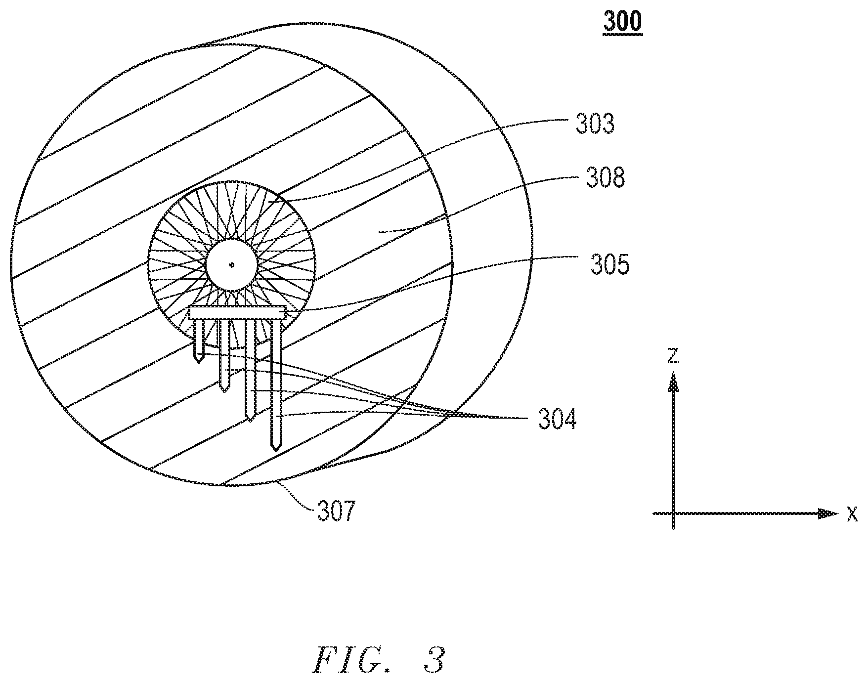
[0008] FIG. 3 includes a side view illustration of an abrasive article according to one embodiment.
[0009] FIG. 4A includes an illustration of a section of an abrasive body before use including portions of the wear detection sensor according to one embodiment.
[0010] FIG. 4B includes an illustration of a section of an abrasive body during a material removing operation including portions of the wear detection sensor according to one embodiment.
[0011] FIG. 5A includes an illustration of one lead of a wear detection sensor according to one embodiment.
[0012] FIG. 5B includes an illustration of one lead of a wear detection sensor according to another embodiment.
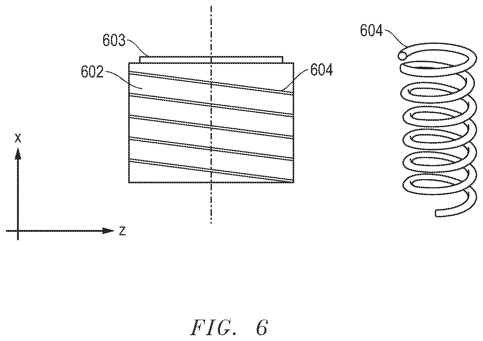
[0013] FIG. 6 includes an illustration of one lead helically wound around an abrasive body according to one embodiment.
[0014] FIG. 7 includes an illustration of a plan view of an abrasive article including a wear detection sensor according to an embodiment.
[0015] FIG. 8 includes an illustration of a plan view of an abrasive article including a detection sensor according to another embodiment.
[0016] FIG. 9A includes an illustration of a wear detection sensor according to an embodiment.
[0017] FIG. 9B includes an illustration of a wear detection sensor according to another embodiment.
[0018] FIG. 9C includes an illustration of a portion of a wear sensor attached to a mounting plate according to an embodiment.
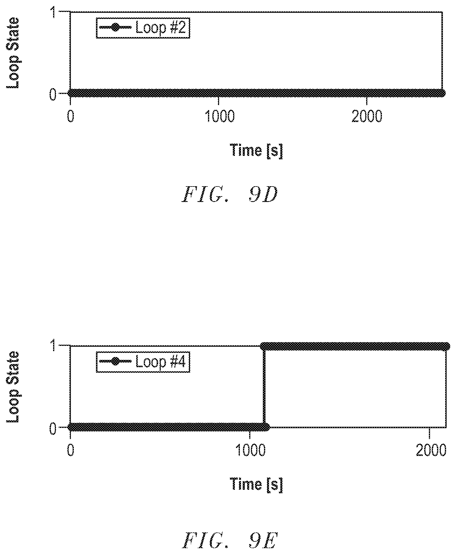
[0019] FIG. 9D includes an illustration of a plot of time vs. loop state for a wear sensor.
[0020] FIG. 9E includes an illustration of another plot of time vs. loop state for a wear sensor.
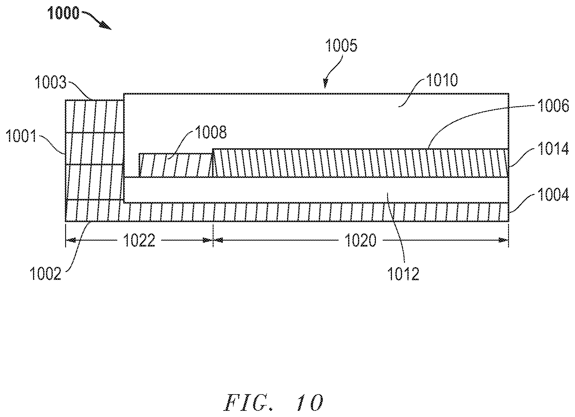
[0021] FIG. 10 includes an illustration of a cross-sectional view of a portion of an abrasive article according to an embodiment.
[0022] FIG. 11 includes an illustration of a plan view of an abrasive article including a detection sensor according to another embodiment.
[0023] FIG. 12 includes an illustration of a plan view of an abrasive article including a detection sensor according to another embodiment.
[0024] FIG. 13 includes an illustration of a plan view of an abrasive article including a detection sensor according to another embodiment.
[0025] FIG. 14 includes an illustration of a plan view of an abrasive article including a detection sensor according to another embodiment.
[0026] FIG. 15 includes an illustration of a section of an abrasive body according to an embodiment.
[0027] FIG. 16A includes an illustration of a plan view of an abrasive article including a detection sensor according to another embodiment.
[0028] FIG. 16B includes a plot of diameter vs. reflected power.
[0029] FIG. 17A includes an illustration of a section of an abrasive body according to an embodiment.
[0030] FIG. 17B includes an illustration of a section of another abrasive body according to an embodiment.
[0031] FIG. 18 includes an illustration of a wear detection system according to an embodiment.
[0032] FIG. 19A includes a plot of reflected power vs. time of an abrasive article according to an embodiment.
[0033] FIG. 19B includes a plot of reflected power vs. time of another abrasive article according to an embodiment.
[0034] FIG. 20 includes an illustration of an exemplary wear sensor.
[0035] FIG. 21 includes an illustration of components of an exemplary reader.
DETAILED DESCRIPTION
[0036] The following description in combination with the figures is provided to assist in understanding the teachings provided herein. The following disclosure will focus on specific implementations and embodiments of the teachings. This focus is provided to assist in describing the teachings and should not be interpreted as a limitation on the scope or applicability of the teachings. However, other teachings can certainly be used in this application.
[0037] As used herein, the terms "comprises," "comprising," "includes," "including," "has," "having" or any other variation thereof, are intended to cover a non-exclusive inclusion. For example, a method, article, or apparatus that comprises a list of features is not necessarily limited only to those features but may include other features not expressly listed or inherent to such method, article, or apparatus. Further, unless expressly stated to the contrary, "or" refers to an inclusive-or and not to an exclusive-or. For example, a condition A or B is satisfied by any one of the following: A is true (or present) and B is false (or not present), A is false (or not present) and B is true (or present), and both A and B are true (or present).
[0038] Also, the use of "a" or "an" is employed to describe elements and components described herein. This is done merely for convenience and to give a general sense of the scope of the invention. This description should be read to include one or at least one and the singular also includes the plural, or vice versa, unless it is clear that it is meant otherwise. For example, when a single item is described herein, more than one item may be used in place of a single item. Similarly, where more than one item is described herein, a single item may be substituted for that more than one item.
[0039] Unless otherwise defined, all technical and scientific terms used herein have the same meaning as commonly understood by one of ordinary skill in the art to which this invention belongs. The materials, methods, and examples are illustrative only and not intended to be limiting. To the extent that certain details regarding specific materials and processing acts are not described, such details may include conventional approaches, which may be found in reference books and other sources within the manufacturing arts.
[0040] Embodiments disclosed herein are directed to an abrasive article including an abrasive body of abrasive particles within a bond material. The abrasive article can include a wear detection sensor configured for detecting a change in a dimension of the abrasive body, wherein at least a portion of the wear detection sensor is coupled to and extending along at least a portion of the abrasive body. As used herein, the phrase "coupled to and extending along at least a portion of the abrasive body" means that at least a portion of the wear detection sensor can be contained at an exterior surface of the body, or being partially embedded in the abrasive body, or being totally embedded in the body of the abrasive article.
[0041] In one embodiment, the wear detection sensor can include at least one lead. The at least one lead can include an electrically conductive structure.
[0042] In one aspect, the lead can include a pair of conductive wires connected together at their ends (i.e., terminal end or lead tip), which can create an electrically conductive loop.
[0043] In another aspect, the lead can be a thin elongated conductive plate or wire adapted to change resistance corresponding to a length of the elongated plate or wire. With increasing wear of the abrasive body, the length of the lead becomes shorter, and the measured change in resistance of the lead with decreasing length of the lead may correspond to the wear of the abrasive body.
[0044] In yet another aspect, the lead can be an electric circuit including two wires connected by a plurality of resistors. The resistors are positioned in parallel to each other at different locations along a length direction of the two wires (i.e., a resistive ladder). As resistors get destroyed during the wear of the abrasive body, the equivalent resistance of the circuit increases and the measured increase in resistance of the circuit can correspond to the state of the wear of the abrasive body.
[0045] The at least one lead of the wear detection sensor can be partially embedded in the abrasive body, completely embedded in the abrasive body, or extend along an exterior surface of the abrasive body.
[0046] As used herein, the term at least one lead is also called plurality of leads if the wear detection sensor contains more than one lead.
[0047] In one aspect, the at least one lead of the wear detection sensor can extend along a portion of the exterior surface of the abrasive body. In another aspect, a majority or the leads of the plurality of leads can extend along a portion of the exterior surface of the abrasive body. In a particular aspect, each lead of the plurality of leads may extend along a portion of the exterior surface of the abrasive body.
[0048] In a further embodiment, at least one lead of the plurality of leads can be embedded within the abrasive body. In a particular embodiment, all of the leads of the plurality of leads may be embedded within the abrasive body.
[0049] In one aspect, the wear detection sensor can have a first portion, e.g., a logic device, and a second portion, e.g., a plurality of leads, wherein the first portion can be coupled to a hub and the second portion can be coupled to the abrasive body. In another aspect, the first portion of the wear detection sensor can be coupled to the abrasive body and the second portion may be coupled to the hub. In another aspect, both the plurality of leads and the logic device can be coupled to the abrasive body.
[0050] FIG. 1 includes an illustration of an abrasive article 100 according to one embodiment.
[0051] The abrasive article (100) can be an abrasive wheel, wherein the abrasive body (102) is coupled to a hub (103). The abrasive body can include a bonded abrasive material, including abrasive particles contained in a three-dimensional matrix of bond material. The abrasive body (102) may optionally include some porosity as a distinct phase from the abrasive particles and bond material. A wear detection sensor can be coupled to the abrasive article (100), such as the abrasive body (102) and/or hub (103) in form of a plurality of leads (104) and a logic device (105). The plurality of leads (104) of the wear detection sensor can be coupled to a portion of the exterior surface of the abrasive body (102). The plurality of leads 104 can extend from the logic device (105) in axial direction (x) of the abrasive body (102) towards the material removing surface (107).
[0052] In another embodiment of an abrasive article illustrated in FIG. 2, the plurality of leads (204) of the wear detection sensor can extend from the logic device (205) in a radial direction (z) of the abrasive body (202), the radial direction (z) being orthogonal to the axial direction (x). FIG. 2 shows a crosscut of an abrasive wheel including an abrasive body (202) attached to a hub (203), wherein all leads of the wear detection sensor (204) can be completely embedded in the abrasive body (202) and point towards the material removal surface (207). The logic device (205) can further optionally include a communication device (e.g., transceiver) (206) for communication with an external controller (not shown).
[0053] FIG. 3 illustrates a side view of an abrasive wheel (300) of the present disclosure. In this embodiment, the plurality of leads of the wear detection sensor (304) can extend along a portion of the exterior surface (308) of the abrasive body. The plurality of leads (304) may be connected to a logic device (305), and the logic device (305) can be coupled to a hub (303). The plurality of leads (304) may extend in a radial direction (z) to the outer material removal surface (307).
[0054] The amount of leads of the wear detection sensor can be at least one lead and may have no specific upper limit. The amount of leads can depend on the thickness of the abrasive body subjected to a material removing process, such as grinding, cutting, or polishing, and in which increments of the wear of the abrasive body should be observed. In one embodiment, the wear detection sensor can include at least one lead, such as at least two leads, at least three leads or at least four leads, at least five leads, at least seven leads, or at least nine leads. In another embodiment, the wear detection sensor can include not more than 100 leads, such as not more than 80 leads, not more than 60 leads, not more than 50 leads, not more than 30 leads, not more than 20 leads, not more than 15 leads, or not more than 10 leads. The amount of leads in the wear detection sensor can be a value within a range including any of the minimum and maximum values noted above.
[0055] The plurality of leads of the wear detection sensor may have different lengths compared to each other. In one embodiment, all the leads can extend parallel to each other from a logic device for different depths into the volume of the abrasive body. In one aspect, each of the leads of the plurality of leads can include a terminal end, and each of the terminal ends can be located at a different position relative to each other. For example, each of the terminal ends may be embedded at different depths within the abrasive body relative to each other.
[0056] In another embodiment, the plurality of leads may extend from the logic device at an angle to each other along the abrasive body. In a further embodiment, the plurality of leads may not be directly coupled to the logic device but can have a connective structure between the logic device and the plurality of leads.
[0057] In one embodiment, each lead can reach with its terminal end up to a defined distance .DELTA.DT from the original material removing surface of the abrasive body, wherein the terminal ends of the leads can be embedded in the abrasive body or extend along an exterior surface of the abrasive body. FIG. 4A illustrates a section of an abrasive body, wherein all leads of the wear detection sensor (404) may be embedded in the abrasive body (402) and the terminal end of each lead can have a defined distance .DELTA.DT1, .DELTA.DT2, .DELTA.DT3, and .DELTA.DT4, from the original material removing surface of the abrasive body (407). Under original material removing surface of the abrasive body (407) should be understood herein the exterior surface of the abrasive body before it is subjected to grinding or cutting of a work piece. In FIG. 4A, the plurality of leads extends in axial direction (x) towards the original material removal surface (407).
[0058] During a material removing operation, the abrasive body of the present disclosure can be subjected to wear, such that portions of the abrasive body may be removed from the original material removing surface. FIG. 4B illustrates a stage of an abrasive article 401 wherein a portion of the abrasive body has been removed from the original outer material removing surface during a material removing operation of a work piece (410), and the terminal end of the longest lead of the plurality of leads (404) has reached the actual material removing surface (409) of the abrasive body (402).
[0059] When the terminal end of a lead reaches the actual material removing surface (409) of the abrasive body (402), the connection between the two wires which conduct current through the lead can be destroyed, thereby opening the electric circuit, and the current between the pair of wires of the lead cannot flow anymore. The open circuit of the broken wire loop can be detected by the logic device and understood herein as a broken lead. From the amount of broken leads detected by the logic device, a calculation can be made about the wear of the abrasive body.
[0060] In another aspect, the plurality of leads can be connected together within one electric circuit, wherein a broken wire loop can cause a change of the total voltage through the complete electric circuit if the total amount of supplied current is remained constant. The amount of change in voltage can be measured as a wear signal by the logic device connected to the plurality of leads and can allow to make conclusions about the wear stage of the abrasive body, such as how much of the abrasive body has been removed from the original outer material removing surface (307) and the remaining life time.
[0061] By knowing the position of the terminal ends of the leads within the abrasive body or along the exterior surface of the abrasive body from the original material removal surface of the abrasive body, the wear stage of the abrasive body during working operation can be calculated by the logic device. In one embodiment, the distance .DELTA.DT of a terminal end of a lead of the plurality of leads from the original removal surface of the abrasive body can be at least 100 microns, such as at least 150 microns, at least 200 microns, at least 500 microns, at least 1000 microns, at least 5000 microns, or at least 10000 microns. In another aspect, the distance .DELTA.DT may be not be greater than 1.5 meters, such as not greater than 1.3 meters, or not greater than 1.0 meter, or not greater than 0.8 meter, or not greater than 0.5 meter, or not greater than 0.3 meter, or not greater than 0.1 meter, or not greater than 0.05 meter, or not greater than 0.01 meter. The distance .DELTA.DT can be a value within a range including any of the minimum and maximum values noted above.
[0062] In a further embodiment, a distance .DELTA.DI between two terminal lead ends to each other in a direction orthogonal to the material removal surface of the abrasive body can be at least 100 microns, such as at least 200 microns, at least 300 microns, or at least 500 microns, or at least 1000 microns, or at least 5000 microns. In another aspect, the distance between two terminal lead ends may be not greater than 1.5 meters, such as not greater than 1.2 meters, or not greater than 1.0 meter, or not greater than 0.8 meter, or not greater than 0.5 meter, or not greater than 0.3 meter, or not greater than 0.1 meter, or not greater than 0.05 meter. The distance .DELTA.DI can be a value within a range including any of the minimum and maximum values noted above.
[0063] In the embodiment wherein each lead of the wear detection sensor is a single wire or elongated plate, the wear detection sensor can be designed that the area of the lead (e.g., the length of the lead) correlates with a certain resistance, wherein the change in resistance with decreasing length of the lead (by increasing wear) can be converted to information about the wear of the abrasive body.
[0064] In one embodiment, the total length of the at least one lead of the wear detection sensor can be at least 100 microns, such as at least 200 microns, or at least 500 microns, or at least 1000 microns, or at least 1 cm, or at least 5 cm. In another aspect, the total length of the at least one lead may be not greater than 10 meters, such as not greater than 8 meters, or not greater than 5 meters, or not greater than 3 meters, or not greater than 2 meters, or not greater than 1.5 meters, or not greater than 1.0 meter, or not greater than 0.8 meter, or not greater than 0.5 meter, or not greater than 0.3 meter, or not greater than 0.2 meter, or not greater than 0.1 meter, or not greater than 0.05 meter, or not greater than 0.01 meter. The total length of the at least one lead can be a value within a range including any of the minimum and maximum values noted above.
[0065] The at least one conductive lead of the wear detection sensor can be in communication with at least one logic device. In one embodiment, the logic device can be a microcontroller configured to detect a change in the states of the wear detection sensor. The logic device can optionally include a communication device, for example, a transceiver, for communication with an external controller.
[0066] In one aspect, the at least one lead of the wear detection sensor can be detected by the logic device being in an active state when a current is flowing through the lead, and being in an inactive state when no or a smaller amount of current is flowing through the lead because the lead is damaged. The interruption or reduction of the current flow in the inactive stage of the lead can create a wear signal. Accordingly, by detecting the wear signals and controlling and measuring the current flowing through the plurality of leads, the wear stage of the abrasive body can be analyzed without interrupting the material removing process.
[0067] The wear signal created by the wear detection sensor can be transmitted by a communication device to an external controller, e.g., a portable control unit in the hand of an operator, or a fixed unit implemented on the machine on which the wheels are mounted. The transmission of the wear signal can be via an electrical connection, for example, to the spindle on which the wheel is mounted, or as a wireless signal. In one aspect, the logic device can include a transceiver, e.g., an RFID transceiver, for sending the wear signals to an external controller which may oversee and control the grinding process. Other options for wireless sending the wear signal can be via Wi-Fi or Bluetooth or other wireless protocols. The wear signals can be stored as local data storage on a logic board (e.g., SD card or flash memory). The external controller can be a part of the logic device or an independent unit. In a further aspect, light indicators can be used to signal that a wheel needs to be replaced or still has a long life time.
[0068] The electrical power needed for operating the wear detection sensor can be provided from a battery, or from a direct electrical connection from a machine or train. The wear detection sensor can also be remotely powered using RF energy or powered by an energy harvesting system, for instance a system producing electrical energy from vibration.
[0069] The material of the at least one conductive lead can be a metal or metal alloy. Non-limiting examples of lead materials can be copper, aluminum, silver, or stainless steel.
[0070] In one embodiment, particularly when the lead has the structure of a wire loop or of a resistive ladder, each lead may be further surrounded or embedded by a protective material. FIG. 5A illustrates an embodiment of one lead (500), which can include a pair of wires (501) connected together by forming a lead end (502) and forming a loop, wherein the wire may be surrounded by a lead protecting material (503).
[0071] FIG. 5B illustrates a lead having the structure of a resistive ladder, wherein two wires (504) are connected by a plurality of resistors (505) placed parallel to each other at different positions along a length direction of the two wires (504). The whole electric circuit is embedded in a protective material (503).
[0072] The lead protecting material can be a material which may protect the wire of the lead during manufacturing of the abrasive article, but can be easily destroyed by the forces during the material removal operation of the abrasive article when it reaches the actual outer material removing surface of the abrasive body. Non-limiting examples of lead-protecting materials can be, e.g., a polyimide, a polyurethane, or a polyolefin. The lead protecting material can also serve as an insulator preventing shorting of the electric circuit, for example, in an embodiment wherein the abrasive body is electrically conductive. In one aspect, at least one wire loop can be directly applied on the exterior surface of the abrasive body and embedded within a protective polymer, e.g., a polyimide. Similarly, if the lead is designed for measuring the change in resistance, the wire or elongated plate can be directly applied on the exterior surface of the abrasive body and embedded within a protective polymeric material.
[0073] In another embodiment, the leads of the wear protection sensor may not include a wire protecting material.
[0074] In yet a further embodiment, the at least one lead can have a spiral form and be wound around an external surface of the abrasive body, as illustrated in FIG. 6. This embodiment may apply for a lead which can change resistance according to its size reduction during wear of the abrasive body. FIG. 6 shows an abrasive body in form of a wheel (602) fixed on a hub (603), wherein the lead (604) is in form of a wire and wound helically around the abrasive body (602) in axial direction (x). In one aspect, the abrasive body can be covered by a reinforcement fiber glass mat (not shown) and the lead can be weaved into the mat or the lead can directly replace some of the threads of the fiber glass mat.
[0075] In another embodiment, the wear detection sensor can include at least one electronic device. In an aspect, the electronic device can include an electronic element. The electronic element can include, for example, a chip, an integrated circuit, logic, a transponder, a transceiver, a passive element, such as a resistor, a capacitor, a memory, or the like, or any combination thereof. In another aspect, the electronic device can include an antenna directly coupled to the electronic element. In a particular aspect, the electronic device can include a chip, an integrated circuit, data transponder, a radio frequency based tag or sensor with or without chip, an electronic tag, electronic memory, a sensor, an analog to digital converter, a transmitter, a receiver, a transceiver, a modulator circuit, a multiplexer, an antenna, a near-field communication device, a power source, a display (e.g., LCD or OLED screen), optical devices (e.g., LEDs), global positioning system (GPS) or device, fixed or programmable logic, or any combination thereof. In some instances, the electronic device may optionally include a substrate, a power source, or both. In a further aspect, the electronic device can be wired or wireless.
[0076] A more particular example of the electronic device can include a tag or sensor, such as a radio-frequency identification (RFID) tag or sensor, a near field communication tag or sensor, or a combination thereof. In an aspect, the electronic device can include a RFID tag. In some instances, the RFID tag can be inactive, and may be powered by a reader device for the RFID tag. In another instance, the RFID tag can be active, including for example, a power supply, such as a battery or inductive capacitive tank circuit.
[0077] In another aspect, the electronic device can include a near-field communication device. A near field communication device can be any device capable of transmitting information via electromagnetic radiation within a certain defined radius of the device, typically less than 20 meters.
[0078] In a particular aspect, the electronic device can include a dual frequency tag. A dual frequency tag can facilitate readability in multiple frequencies. For instance, the electronic device can include a near-field communication device and an RFID tag. In a further instance, the electronic device can include a dual frequency chip attached to an RFID antenna and an NFC antenna.
[0079] In a further aspect, the electronic device can include a transceiver. A transceiver can be a device that can receive information and/or transmit information. Unlike passive RFID tags or passive near-field communication devices, which are generally read-only devices that store information for a read operation, a transceiver can actively transmit information without having to conduct an active read operation. Moreover, the transceiver may be capable of transmitting information over various select frequencies, which may improve the communication capabilities of the electronic device with a variety of systems that are intended for receiving and/or storing the information.
[0080] In an aspect, the electronic device can be attached to at least a portion of the abrasive body. For example, the electronic device can be attached to a portion of a surface of the abrasive body, such as to a major surface, a peripheral surface, or a combination thereof. In a further aspect, the electronic device can be in contact with the abrasive body. In another aspect, the electronic device can be partially embedded in the abrasive body. In a further aspect, the electronic device can be fully embedded within the abrasive body.
[0081] In some implementations, the electronic device can be adapted to detect wear of the abrasive article, such as a dimension change of the abrasive body. In other implementations, the electronic device may be combined with another component to facilitate wear detection.
[0082] FIG. 7 includes an illustration of a plan view of an abrasive article 700 including an abrasive body 701 and a wear detection sensor 702. The body 701 can include a center hole 713. In some instances, the abrasive body 701 can include an interior circumferential region 704 that abuts the center hole 703 and an exterior circumferential region 705 that is outside of the interior circumference region 705. The interior circumferential region can include an interior circumferential diameter D.sub.I, and the abrasive body can include an outer diameter D.sub.O that may also be referred to as an exterior circumferential region diameter in this disclosure.
[0083] In an embodiment, wear of the abrasive article can include a dimension change including reduction in the outer diameter D.sub.O. For instance, a peripheral surface of the abrasive body may be the material removing surface in contact with a work piece. Material loss on the material removing surface can cause a reduction in the outer diameter D.sub.O. In certain applications, when the outer diameter D.sub.O is reduced to approximately the size of the inner diameter D.sub.I, the abrasive article may not be suitable for further use. In another embodiment, a major surface of the abrasive body can be the material removing surface.
[0084] The wear detection sensor 702 can include an electronic device 710 including an electronic element 712, such as an integrated circuit, coupled to an antenna 714. In some implementations, the electronic device 710 can include an integrated circuit and may not include an antenna. The electronic device 710 can be placed within the interior circumferential region 704 or within the exterior circumferential region 705 or extending along a portion of the interior circumferential region 704 and a portion of the exterior circumferential region 705. In a particular instance, the electronic device 710 can be placed within the interior circumferential region 704, as illustrated.
[0085] The wear detections sensor 702 can further include an electrical component coupled to the electronic device 710. The electrical component can include a passive element, such as a capacitor, a resistor, an inductor, or combination thereof. In a particular instance, the electrical component can include a first capacitance plate 718 and a second capacitance plate 720. The first and second capacitance plates 718 and 720 can be coupled to the electronic device 710, such as by wires 716.
[0086] The first capacitance plate 718 and the second capacitance plate 720 can be spaced apart and may be placed in parallel to each other. In some instances, the first capacitance plate 718 can be placed in the interior circumferential region 704 and the second capacitance plate 720 can be placed in the exterior circumferential region 705.
[0087] In an exemplary material removing operation, wear of the abrasive article may result in removal of a portion of or the entire second capacitance plate 720, which can cause the electric field strength in the capacitor plates to change. The electronic device 710 can detect the change and generate a wear signal.
[0088] In other instances, the electrical component can include a resistor, inductor, or a combination thereof. In an exemplary material removing operation, a portion of the resistor, inductor, or both may be removed, which may cause the current or magnetic filed to change, which can lead to generation of a wear signal.
[0089] The wear signal can be received by a data-receiving device and the operator may be warned of the wear condition of the abrasive article.
[0090] In an embodiment, a data-receiving device can include a reader, an interrogator, or another device that can receive, read, store, and/or edit data. In some instances, the data-receiving device can read data stored in the electronic device, and the electronic device may not function to transmit data. In another embodiment, the data-receiving device can transmit data from the electronic device to another device, system, a database, or the like. In particular embodiment, the data-receiving device can include a RFID reader or interrogator, an NFC reader, a mobile phone, or a combination thereof.
[0091] As illustrated in FIG. 7, the wear detection sensor 702 can be positioned over a major surface of the abrasive body 701. In another embodiment, at least a portion of the wear detection sensor 702 can be attached to a portion of the major surface, peripheral surface, or both. For example, the electronic device, the electrical component, the wire, or any combination thereof, may be directly cold pressed, warm pressed, or hot pressed onto a surface of the abrasive body. In another example, at least a portion of the wear detection sensor may be disposed on a surface of the abrasive body during a forming process of the abrasive body, and co-cured with the abrasive body. In a further instance, at least a portion of the wear detection sensor may be attached to the surface by heat, radiation, glues, adhesives, in a mechanical manner, or any combination thereof.
[0092] In an embodiment, the wear detection sensor 702 can be in contact with a portion of the abrasive body 701. For example, the wear detection sensor 702 can be in direct contact with the bond material, abrasive particles, another component of the abrasive body 701, or the combination thereof. In another embodiment, the wear detection sensor 702 can be partially embedded or entirely embedded within the abrasive body. In some instances, a portion of the abrasive body may be removed to create a space (e.g., a slot) inside the abrasive body to receive the wear detection sensor, and heat, pressure, adhesives, glue, or any combination thereof, may be used to attach the wear detection sensor to at least a portion of the body. In some other instance, the wear detection sensor may be embedded in a mixture for forming the abrasive body during the forming process. The mixture can include the bond material, abrasive articles, and optionally additives. In a particular example, the mixture and the wear detection sensor can be placed in a mold, wherein the wear detection sensor can be partially or fully embedded in the mixture. The abrasive body can then be formed by subjecting the mixture to pressure, heat, irradiation, other known processes for forming an abrasive body, or a combination thereof.
[0093] As illustrated, at least a portion of the electrical component, such as the first and second capacitance plates 718 and 720, can be placed on a major surface of the abrasive body 701. In a particular instance, a portion of the electrical component, such as at least one of the capacitance plates 718 and 720, can be attached to a portion of the abrasive body. In another particular instance, the first and second capacitance plates 718 and 720 can be attached to a portion of a major surface, a peripheral surface, or both. In a more particular instance, at least one of the first and second capacitance plates 718 and 720 can be in contact with a portion of the abrasive body including the bond material, abrasive particles, another component, or any combination thereof.
[0094] In some implementations, at least one of the capacitance plates 718 and 720 can be partially or fully embedded in the abrasive body 701. For instance, the first capacitance plate 718 can be placed on a major surface or a peripheral surface, and the second capacitance plate can be partially or fully embedded in the abrasive body 701. In another instance, the second capacitance plate 720 can be placed on a major surface or a peripheral surface, while the first capacitance plate 718 can be partially or fully embedded in the abrasive body 701. In another instance, both the first and second capacitance plates 718 and 720 can be partially or fully embedded in the abrasive body 701.
[0095] In another embodiment, the wear detection sensor can include a loop circuit coupled to the electronic device. FIG. 8 includes an illustration of a plan view of another exemplary abrasive wheel 800 including an abrasive body 801. The abrasive article 800 includes a wear detection sensor 802 including an electronic device 810 placed on a major surface 803. The electronic device 810 can include an electronic element, and optionally, an antenna 814 coupled to the electronic element 812. The wear detection sensor 802 can include a loop circuit. In some applications, the loop circuit can include a wire loop 820 coupled to the electronic device 810. For instance, the wire can be resistive. The wire loop can be directly connected to the electronic element 812, such as an integrated circuit. Alternatively, the wire loop can be coupled to the electronic element 812 by the antenna 814.
[0096] In another application, the loop circuit can include a passive element, such as a capacitor, a resistor, an inductor, or a combination thereof. In a particular application, the loop circuit can include a capacitive loop circuit including at least one capacitor. In another particular application, the loop circuit can include at least one resistor. In another particular instance, the loop circuit can include a plurality of capacitive loop circuits, where capacitors are placed in parallel connected by a wire.
[0097] FIG. 9A includes an illustration of a wear detection sensor 900 including an electronic device 901 coupled to a loop circuit 902. The electronic device 901 can include an electronic element 905, such as a transponder, integrated circuit, or the like, and antenna 903 coupled to the electronic element 905. The loop circuit 902 can include a plurality of capacitors 911, 912, and 913 placed in parallel. In another instance, at least one or all of 911, 912, and 913 can include a resistor.
[0098] In an embodiment, the wear detection sensor 802 or 900 may be placed on a major surface 803, a peripheral surface (not illustrated), or a combination thereof, of the abrasive body 801. In an aspect, the length L.sub.L of the loop circuit 820 or 902 can extend along a portion of the major surface, the peripheral surface, or both. In another aspect, the length L.sub.L of the loop circuit 820 or 902 can extend in a radial direction, an axial direction, or a combination thereof, of the abrasive body 801. In another instance, the length L.sub.L of the loop circuit 820 or 902 can extend toward the material removing surface to facilitate wear detection.
[0099] In a further embodiment, at least a portion of the wear detection sensor 802 or 900 can be embedded in the abrasive body 801. In an aspect, the loop circuit 820 or 902, the electronic device 810 or 901, or both can be partially embedded in the abrasive body. In another aspect, the loop circuit 820 or 902, the electronic device 810 or 901, or both can be fully embedded in the abrasive body.
[0100] In another embodiment, the wear detection sensor 802 or 900 can be placed in a certain position that can facilitate determination of the wear level. For example, in a material removal operation, a first portion of the wear detection sensor can be removed and a first wear signal can be generated, when wear of the abrasive body reaches a first level. The first wear signal can be an indicator of a first wear level. The first wear level may be a relatively low wear level, such as 20%, 30%, or 40%. As the operation continues, a second portion of the wear detection sensor may be removed and a second wear signal is generated, when a second wear level is reached. The second wear signal can be an indicator of a second wear level. The second wear level may be a relatively higher wear level, such as 705, 80%, or 90%. The second wear signal can be interpreted as a warning of the upcoming end-of-life of the abrasive article.
[0101] Referring to FIG. 8, the loop circuit 820 can extend in the radial direction toward the peripheral surface. The peripheral surface can be the material removing surface. The wear detection sensor 810 may be positioned such that in a material removal operation, a certain length of the circuit loop 820 or 902 can be removed to cause the circuit loop to break, as wear of the abrasive body reaches a certain level. The electronic device can sense the broken circuit loop and generate a wear signal. A data-receiving device can receive the wear signal and interpret it as an indicator that the certain wear level, such as a certain low level wear, is reached. As the operation continues, a portion of the electronic device 810, such as at least a portion of the electronic element 812, antenna 814, or both, may be removed, which may turn the electronic device into an inactive state, and the data-receiving device may receive a wear signal indicating a higher level of wear is reached. A wear signal can include a change in a signal, such as a change in response time, signal strength, reflected energy, disappearance of existing signal, or any combination thereof. In certain instances, as the electronic device becomes inactive, the data-receiving device may stop receiving any signal or response from the electronic device.
[0102] In some instances, the electronic device 810 may be damaged gradually during an operation of the abrasive article 800, and the received signal strength indicator on the data-receiving device may be used to determine the level of wear, as the electronic device 810 may send a progressively weaker signal until the electronic device 810 turns inactive. The value of the received signal strength indicator can be measured, calculated, or both by the data-receiving device to determine the level of wear.
[0103] FIG. 9B includes an illustration of another example of the wear detection sensor 950 including a wire loop 951 coupled to an electronic device 952. In an embodiment, the wire loop 951 can include one or more wire loops, such as 1 loop, 2 loops, 3 loops, 5 loops, or more. The electronic device 952 can include an integrated circuit 954 and an antenna 953. In a particular embodiment, the electronic device 952 can include an RFID chip or integrated circuit. The electronic device 952 may further include additional components 955, such as a chip, another integrated circuit, a logic device, a transponder, a transceiver, a passive element, or the like, or any combination thereof. In some implementations, the wear detection sensor 950 can be printed and include a substrate 956. The substrate 956 can include a flexible material, such as an organic material, and more particularly, a flexible material. A more particular example of the substrate 956 can include PET, polyimide, or another material that can be used to make flexible electronics.
[0104] In certain implementations, the wear detection sensor 950 can be placed abut an outer surface, such as the peripheral surface, of the abrasive body of an abrasive article. For example, the wear detection sensor 950 can be placed around at least a portion of the peripheral surface of the abrasive body, and a non-abrasive portion, such as a layer of fiber, can be wound over the wear detection sensor 950 and at least a portion or the entire outer peripheral surface of the abrasive body.
[0105] FIG. 9C includes an illustration of a top view of a mounting plate (or a hub) 981 attached with an electronic assembly 982 including an electronic device 983 contained within a package 985. The package 985 and the stool spokes 988 can help protect the electronic device 983 from sparks and heat generated during a grinding operation. In an embodiment, the package 985 can include a protecting material that can be resistant to high temperatures and function as a heat shield. In another embodiment, the package 985 can include a polymer. A particular example of the polymer can include a high performance polymer, such as polyether ether ketone (PEEK) or the like or a combination thereof. Alternatively, the electronics device 983 may be completely covered by a protecting material in lieu of the package and separated from the outer environment.
[0106] The electronic device 983 can be part of a wear sensor that further includes wire loops attached to the electronic device 983. In a particular embodiment, the electronic device 983 can include a microcontroller, and the wire loops can be attached to the microcontroller. The wire loops can also be attached to a peripheral surface of the abrasive body that is attached to the mounting plate 981. The peripheral surface can be the inner or outer peripheral surface. In an implementation, a coating may be applied to the wire loops to facilitate attachment of the wire loops to the peripheral surface and provide protection against heat and sparks. In an embodiment, the coating can include an adhesive. In another embodiment, the coating can be heat resistant. In particular instances, the coating can include a heat resistant adhesive, which may facilitate improved performance of the wear sensor. An exemplary adhesive can include epoxy, acrylates, silicone rubber, or the like. In a particular embodiment, the coating can include steel epoxy.
[0107] In some instances, signal transmission from the electronic device 983 during a grinding operation can be wireless. For example, wheel wear information can be sent via Wi-Fi, Bluetooth, or a combination thereof, to a receiving device, such as a mobile phone, a hand held device, a computer, or the like. The transmitted data can include state and change of state of the wire loops. For instance, data may be in the format in which "0" represents closed loop (e.g., no detectable wear of the wire loop), and "1" represents open loop (broken loop). State and/or change of state of wear loops can be used to determine the level of wear of the abrasive tool. FIGS. 9D and 9E include graphs illustrating data transmitted by a wear sensor including wire loops attached to the electronic device 983, indicating state of different wire loops in a grinding operation. As illustrated, the wire loop #2 is closed and has no state change, while the state of the wire loop #4 changes from 0 to 1 indicating the wire loop is broken during the grinding operation and some level of wear of the grinding tool. As grinding continues, the wire loop#2 can be broken at a later time to indicate a higher level of wear of the grinding tool.
[0108] FIG. 10 includes an illustration of a cross section of a portion of an abrasive article 1000 including a body 1001. The body 1001 can include a first major surface 1002 opposite a second major surface 1003, and a peripheral surface 1004 extending between the first and second major surfaces 1002 and 1003. In some instances, the body 1001 can include an abrasive portion 1020 and a non-abrasive portion 1022. The peripheral surface 1004 can be the material removing surface of the abrasive article 1000.
[0109] The wear detection sensor 1005 can be at least partially embedded in the body 1101, including an electronic device including an electronic element 1008 and an antenna 1006 coupled to the electronic element 1008. The electronic element 1008 may be placed within the non-abrasive portion 1022. In some instances, a portion of the electronic element 1008 may be placed in the abrasive portion 1020. The antenna 1006 is placed in the abrasive portion 1020, and in some instances, a portion of the antenna may be placed in the non-abrasive portion. The terminal end 1014 of the antenna 1006 can be aligned with the peripheral surface 1004.
[0110] The antenna 1006 can extend toward the peripheral surface 1004. For instance, the antenna 1006 can extend in the radial direction along a portion of the body. In another instance, the antenna 1006 can extend over an entire radial distance of the abrasive portion.
[0111] In some instances, the wear detection sensor can include a package that contains at least a portion of the electronic element 1008 and the antenna 1006. For instance, the package can separate the electronic element 1008 and/or the antenna 1006 from a surrounding environment. In another instance, the package can separate the electronic element 1008 and/or the antenna 1006 from the composition of the body 1001, such as abrasive particles, the bond material, and other components.
[0112] The package may include, such as a protective layer 1010, a substrate 1012, or both. A portion of the protective layer 1010 may extend above the major surface 1003. Alternatively, the protective layer 1010 can be beneath the major surface 1003 or at the same plane as the major surface 1003. In an aspect, the protective layer 1010 may include a material that can protect the electronic element 1008 and/or antenna 1006 from an outer environment condition, including such as moisture, coolant, or the like. An exemplary protective material can include polydimethylsiloxane (PDMS), polyethylene naphthalate (PEN), polyimide, polyether ether ketone (PEEK), or any combination thereof.
[0113] In some instances, certain coolant is used in material removal operations, and exposing an electronic device to the coolant can cause degradation of the electronic device. The protective layer 1010 or the entire package can be applied to protect the electronic device from the coolant and extend service life of the electronic device. The protective layer can also be applied to protect the electronic device from moisture, harsh temperatures, or other conditions that may damage the electronic device.
[0114] In an aspect, the substrate 1012 can include a similar or different material as the protective layer 1010. In a particular instance, the package may encapsulate the electronic device.
[0115] The wear detection sensor 1005 can survive multiple material removal operations, and serve as an indicator that high level of wear is reached when the abrasive article 1000 is retired. For instance, the remaining length of the electronic element 1008 can be an indicator that the interior circumference is reached at the time the abrasive article 1000 is replaced.
[0116] In an embodiment, the wear detection sensor can include an electronic device including an antenna directly and electrically connected to an electronic element. In another embodiment, the wear detection sensor can include a plurality of electronic devices, wherein at least one of the electronic devices can include an antenna directly and electrically connected to an electronic element. In still another embodiment, the wear detection sensor can include a plurality of electronic devices, wherein at least some or each of the electronic devices can include an antenna directly and electrically connected to an electronic element. In some implementations, the antenna can include a thin film antenna.
[0117] In an aspect, the antenna can extend along a portion of the abrasive body. For instance, the antenna can extend along a portion of a major surface, a peripheral surface, or both, toward a material removing surface of the abrasive body. In another aspect, the antenna can extend in a radial direction, an axial direction, or combination thereof of the abrasive body. In a further aspect, the antenna may be partially or fully embedded in the abrasive body.
[0118] In an aspect, the electronic device can include at least 1 antenna, at least 2 antennas, at least 3 antennas, or at least 4 antennas, wherein each antenna is directly and electrically connected to an electronic element. In an aspect, at least some of the antennas may extend a different distance along the abrasive body. In another aspect, each of the antennas can extend a different distance along the abrasive body.
[0119] FIG. 11 includes an illustration of a plan view of an abrasive article 1100 including a body 1101 including an interior circumferential region 1103 and an exterior circumferential region 1102. The wear detection sensor 1104 can include an electronic device including an electronic element 1105 and a plurality of antennas 1106 to 1109 coupled to the electronic element 1105. The electronic element 1105 can be placed within the interior circumferential region 1103. In another instance, the electronic element 1105 may be placed in the exterior circumferential region 1102. In some particular implementations, the electronic element 1105 can include an integrated circuit, a transponder, or a combination thereof.
[0120] The antennas 1106 to 1109 can be spaced apart from one another. As illustrated, the antennas 1106 to 1109 can extend such that the lengths of the antennas are in parallel to one another. In another instance, at least some of the antennas 1106 to 1109 can be placed such that the lengths may extend at an angle to each other. For example, the angle can include an acute angle, an obtuse angle, a right angle, or a combination thereof.
[0121] The antennas 1106 to 1109 can extend along a portion toward a material removing surface (e.g., the peripheral surface) of the abrasive body. In an aspect, one of the antennas can extend a different distance compared to one of the other antennas. In another aspect, all the antennas can extend a different distance along the abrasive body.
[0122] In a further aspect, at least some of the antennas 1106 to 1109 can include different lengths compared to one another. In a particular aspect, each of the antennas 1106 to 1009 can include a different length. For example, a relative difference in length between the antennas can be at least 5%, at least 10%, at least 15%, at least 17%, at least 20%, at least 30%, at least 40%, or at least 50%. In another aspect, a relative difference in length between the antennas can be at most 80%, at most 70%, at most 60%, at most 50%, at most 45%, at most 40%, at most 35%, or at most 30%. Moreover, the relative difference in length between the antennas can be in the range including any of the minimum and maximum percentages noted herein.
[0123] As illustrated, the antennas 1109 can be placed within the interior circumferential region 1103. The other antennas 1106 to 1108 can extend from a position within the interior circumferential region 1103 into the exterior circumferential region 1102 for a different distance.
[0124] The antennas 1106 to 1109 can be spaced apart from the centerline 1111 of the abrasive body 1101 by a distance .delta.d.sub.C. As illustrated, .delta.d.sub.C is the vertical distance from a terminal end of the antenna (e.g., 1106) to the centerline 1111, wherein the terminal end is the one that is closer to the centerline 1111. For example, a relative difference in distance .delta.d.sub.C between at least some of or all of the antennas 1106 to 1109 can be at least 2%, at least 5%, at least 10%, at least 15%, or at least 20%. In another instance, a relative difference in distance .delta.d.sub.C can be at most 40%, at most 35%, at most 20%, at most 15%, or at most 10%. Moreover, the relative difference in .delta.d.sub.C can be in the range including any of the minimum and maximum percentages noted herein.
[0125] The other terminal end of each antenna can be spaced apart from the outer circumference of the abrasive body 1101 by a distance .delta.d.sub.O. The distance is the linear extension from the terminal end of the antenna (e.g., 1106) to the outer circumference. The distance .delta.d.sub.O between the antennas 1106 to 1109 may be different. For example, a relative difference in distance .delta.d.sub.O between at least some of or all of the antennas 1106 to 1109 can be at least 2%, at least 5%, at least 8%, at least 10%, or at least 15%. In another instance, a relative difference in distance .delta.d.sub.O can be at most 45%, at most 40%, at most 35%, at most 30%, or at most 25%. Moreover, the relative difference in .delta.d.sub.O can be in the range including any of the minimum and maximum percentages noted herein.
[0126] In an exemplary material removal operation of the abrasive article 1100, the longest antenna 1107 may come into contact with the actual material removing surface (e.g., the peripheral surface) and a portion of the antenna 1107 may be removed. As wear of the abrasive article progresses, portions of antennas 1108, 1106, and 1104 may be removed. As the sizes of the antennas reduce, the response energy from the electronic device decreases. The data-receiving device can sense the changes in received signals and the operator can be warned of wear. In some instances, the data-receiving device may calculate the changes in response energy and calculate to indicate the level of wear.
[0127] In an embodiment, the wear detection sensor can include an electronic device including an electronic element and an antenna, wherein the antenna can include a greater surface area than the electronic element. For example, the electronic device can include a plurality of antennas coupled to an electronic element, wherein at least one, some, or each of the antennas can have a surface greater than a surface area of the electronic element.
[0128] In another instance, the wear detection sensor can include a plurality of electronic devices, wherein at least one of the electronic devices can include an antenna coupled to an electronic element, wherein the antenna can have a surface area bigger than the electronic element. In a particular instance, some or each of the plurality of electronic devices can include an antenna coupled to an electronic element, wherein the antenna can have a surface area bigger than the electronic element. In another particular instance, one or more of the plurality of electronic devices can include a plurality of antennas coupled to an electronic element, wherein at least one or more of the plurality of antennas can have a bigger surface area than the electronic element. In a more particular instance, all of the antennas can have a surface arear greater than the electronic elements they are coupled to.
[0129] In an embodiment, the electronic device can be positioned at a non-abrasive portion, an abrasive portion, or both, of the body of the abrasive article. In some instances, the antenna can be coupled to an electronic element can be positioned at a non-abrasive portion of the body of the abrasive article. As used herein, non-abrasive portion is intended to refer to a portion of an abrasive article body that is essentially free of an abrasive particle. The non-abrasive portion may or may not include a bond material. Abrasive portion is intended to refer to a portion of an abrasive article body that includes a bond matrix and abrasive particles contained in the bond matrix. The abrasive body is intended to refer to a bonded body including a bond matrix and abrasive particles distributed through the bond matrix, wherein the bonded body is essentially free of a non-abrasive portion.
[0130] In an embodiment, the wear detection sensor can include an antenna including a flared body. In some instances, the wear detection sensor can include a plurality of antennas, wherein one or more of the antennas can include a flared body. FIG. 12 includes an illustration of a plan view of an abrasive article 1200 including an abrasive body 1201 including an interior circumferential region 1214 and an exterior circumferential region 1215. In some instances, the body can include a center region 1213. The center region may include a flange region or a hub.
[0131] A wear detection sensor 1203 can include the first electronic device 1204 including an electronic element 1205 placed in the center region 1213 and an antenna 1207. The second electronic device 1208 includes an electronic element 1209 positioned in the interior circumferential region 1214 and an antenna 1211. In another instance, the first and second electronic elements 1205 and 1209 can be placed out side of the center region 1213. In still another instance, both of the first and second electronic elements 1209 and 1205 can be placed in the interior circumferential region 1214. In yet another instance, one of the first and second electronic elements 1205 and 1209 can be placed in the interior circumferential region 1214 and the other can be placed in the exterior circumferential region 1215. In a particular instance, none of the electronic elements is placed in the exterior circumferential region 1215. In another particular instance, at most one of the electronic elements can be placed in the center region 1213. In a more particular instance, at least some of the electronic elements are placed in different regions including the center region 1213, the interior circumferential region 1214, and the exterior circumferential region 1215.
[0132] The antennas 1207 and 1211 can be spaced apart from one another in the circumferential direction, in the radial direction, in the axial direction, or any combination thereof, of the abrasive body 1201. The antennas 1207 and 1211 can extend in the radial direction, axial direction, or a combination thereof along a portion of the abrasive body. The antennas 1207 can extend from a location in the center region 1213, across the entire radial distance of the interior circumferential region 1214, and into the exterior circumferential region 1215. The terminal end of the antenna 1207 can be spaced apart from or aligned with the outer circumference or the material removing surface (e.g., peripheral surface) of the abrasive body. As illustrated, one of the terminal ends of the secondary antenna 1207 can reach the outer circumference or the material removing surface.
[0133] The antenna 1211 can extend from a location in the interior circumferential region 1214 into the exterior circumferential region 1215. At least one of the antenna 1211 can have a terminal end that can reach the outer circumference.
[0134] As illustrated, each of the secondary antennas 1207 and 1211 can include a flared body. The width of the body can increase as the secondary antennas 1207 and 1211 extend toward the outer circumference or peripheral surface. For instance, the width W at the terminal end of the secondary antenna 1207 or 1211 that is closer to the outer circumference of the body 1201 can be greatest compared to a width of another portion of the antenna.
[0135] In some instances, the antenna 1207 or 1211 or both can be attached to a major surface of the abrasive body 1201. For instance, the antenna 1207 or 1211 or both can extend along a portion of a major surface of the abrasive body. In another instance, a portion of the antenna 1207 or 1211 or both can be exposed to an outer environment. For instance, the secondary antenna 1207 or 1211 or both can be partially embedded in the abrasive body 1201. In another instance, the antenna 1207 or 1211 or both can include a portion protruding outside of a surface portion of an interior circumferential region 1214 of the abrasive body 1201.
[0136] In other instances, the antenna 1207 or 1211 can extend over a greater surface area of the abrasive body compared to the electronic device 1204 or 1205, while in a shape other than a flared body. For instance, the antenna 1207 and/or 1211 can be in a shape including a triangle, a rectangle, a square, or an irregular shape. The antenna 1207 and 1211 can be in the same or different shape.
[0137] In another instance, any or each of the antennas 1207 and 1211 can extend over a certain surface area of the abrasive body that can facilitate improved data transmission and/or continuous powering the electronic devices 1204 and/or 1208. For instance, any or each of the antennas 1207 and 1211 can extend over at least 1/20 of the surface area of a major surface or a peripheral surface of the abrasive body 1201, such as at least 2/20, at least 3/20, at least 4/20, or at least 5/20 of the surface area of a major surface or a peripheral surface of the abrasive body 1201. In another instance, any or each of the antennas 1207 and 1211 can extend over at most 10/20 of the surface area of a major surface or a peripheral surface of the abrasive body 1201, such as at most 9/20, at most 8/20, at most 7/20, at most 6/20, at most 5/20, at most 4/20, or at most 3/20 of the surface area of a major surface or a peripheral surface of the abrasive body 1201. Moreover, any or each of the antennas 1207 and 1211 can extend over a surface area including any of the minimum and maximum values noted herein.
[0138] FIG. 13 includes an illustration of a plan view of an abrasive article 1300 including an abrasive body 1301. The abrasive body 1301 can include an interior circumferential region 1302 and an exterior circumferential region 1303. In some instances, the abrasive body 1301 can include a center region 1310.
[0139] The wear detection sensor 1304 can include a first electronic device including an electronic element 1305 coupled to an antenna 1306, and a second electronic device including an electronic element 1307 coupled to an antenna 1308.
[0140] The antennas 1307 and 1308 can include a curved portion that can extend in the circumferential direction of the abrasive body 1301. In a particular instance, the antennas 1307 and 1308 can include a length that can extend in the circumferential direction. In a further instance, the antenna 1307, 1308, or both can extend in a circumferential direction, an axial direction, a radial direction, or any combination thereof. In another instance, the antenna 1307 and 1308 can have the same or different length.
[0141] In another instance, the antenna 1306, 1308, or both can extend for a certain length along a portion of the abrasive body 1301. In an aspect, the antenna 1307, 1308, or both can extend along a portion of a major surface, peripheral surface, or a combination thereof. In another aspect, one or each of the antennas 1307 and 1308 can extend for a certain length that can facilitate improved data transmission and/or continuous powering. For instance, one or each of the antennas 1307 and 1308 can extend for at least 1/10 of the outer circumference of the abrasive body 1301, such as at least 2/10, at least 3/10, at least 4/10, at least 5/10, at least 6/10, or at least 7/10 of the outer circumference of the abrasive body 1301. In another instance, one or each of the antennas 1307 and 1308 can extend for at most 9/10, of the outer circumference of the abrasive body 1301, such as at most 8/10, at most 7/10, at most 6/10, at most 5/10, or at most 4/10 of the outer circumference of the abrasive body 1301. Moreover, one or each of the antennas 1307 and 1308 can extend for a length in a range including any of the minimum and maximum values noted herein.
[0142] In another instance, any or each of the antennas 1306 and 1308 can extend over a certain surface area of the abrasive body that can facilitate improved data transmission and/or continuous powering the electronic devices 1305 and/or 1307. For instance, any or each of the antennas 1306 and 1308 can extend over at least 1/20 of the surface area of a major surface or a peripheral surface of the abrasive body 1301, such as at least 2/20, at least 3/20, at least 4/20, or at least 5/20 of the surface area of a major surface or a peripheral surface of the abrasive body 1301. In another instance, any or each of the antennas 1306 and 1308 can extend over at most 10/20 of the surface area of a major surface or a peripheral surface of the abrasive body 1201, such as at most 9/20, at most 8/20, at most 7/20, at most 6/20, at most 5/20, at most 4/20, or at most 3/20 of the surface area of a major surface or a peripheral surface of the abrasive body 1301. Moreover, any or each of the antennas 1306 and 1308 can extend over a surface area including any of the minimum and maximum values noted herein.
[0143] As illustrated, each of the antennas 1306 and 1308 can have an arc shape. The antennas 1306 and 1308 can extend toward each other and be spaced apart in the radial direction, the axial direction, the circumferential direction, or a combination thereof.
[0144] The antennas 1306 and 1308 can extend along a portion of the interior circumferential region 1302, a portion of the exterior circumferential region 1303, or both. In some instances, the antennas 1306 and 1308 and the electronic devices 1305 and 1306 may be placed outside of the center region 1310. In another instance, one of the electronic devices 1307 and 1305 may be placed in the center circumferential region 1310 or the exterior circumferential region 1303.
[0145] In some instances, one or each of the antennas 1306 and 1308 can extend along a portion of a major surface of the abrasive body. In a particular instance, one or each of the antennas 1306 and 1308 can be attached to a major surface of the abrasive body. In another instance, one or each of the antennas 1306 and 1308 is at least partially embedded in the abrasive body. In a further instance, at least one or each of the antennas 1306 and 1308 can include a portion exposed to an outer environment. In a particular instance, at least one or each of the antennas 1306 and 1308 can include a portion protruding outside of a surface portion of the interior circumferential region 1302.
[0146] In another embodiment, the wear detection sensor can include a certain number of an electronic device that can facilitate improved response of the electronic device to a data-receiving device. For instance, the wear detection sensor can include at least 1 electronic device, such as at least 2, at least 3, at least 5, at least 6, or at least 7 electronic devices. In a further embodiment, the wear detection sensor can include at most 45 electronic devices, at most 40, at most 35, at most 30, at most 25, at most 20, at most 15, at most 12, at most 10, at most 9, or at most 8 electronic devices. Moreover, the number of the electronic devices can be in the range including any of the minimum and maximum values noted herein. For instance, the wear detection sensor can include 1 to 45 electronic devices.
[0147] In an aspect, the wear detection sensor can include a plurality of electronic devices that are spaced apart from one another in the radial direction, the axial direction, the circumferential direction, or a combination thereof. In another aspect, at least some of the plurality of electronic devices may be placed in an angle to one another. In another aspect, some of the electronic devices may be aligned in the radial direction. In still another aspect, some of the electronic devices may be in parallel. In a further aspect, the plurality of electronic devices can extend toward a material removing surface of the abrasive body.
[0148] FIG. 14 includes an illustration of a plan view of an abrasive article 1400 including an abrasive body 1401 and a wear detection sensor including a plurality of electronic devices 1402 extending along a portion of the abrasive body 1401. The plurality of electronic devices 1402 can include the same or different electronic devices including any of the electronic devices noted in embodiments of this disclosure. In a particular instance, the plurality of electronic devices 1402 can include a RFID tag or sensor, an NFID tag or sensor, or any combination thereof.
[0149] In some instances, one or more of the electronic devices 1402 can extend along a portion of major surface, a peripheral surface, or a combination thereof, of the abrasive body 1401. In another instance, one or more or each of the electronic devices 1402 can be partially embedded or fully embedded in the abrasive body.
[0150] The abrasive body 1401 can include an interior circumferential region 1404 and an exterior circumferential region 1403. The plurality of electronic devices 1402 can be placed in the exterior circumferential region 1403. In some instances, one or more of the electronic devices 1402 may be placed in the interior circumferential region 1404. In a further instance, one or more of the electronic devices 1402 may extend along a portion of the interior circumferential region 1404 and a portion of the exterior circumferential region 1403. In another instance, one or more of the electronic devices 1402 can include a terminal end that is aligned with a material removal surface of the abrasive body 1401.
[0151] At least some of the electronic devices 1402 can include an electronic element 1410 and antenna 1411. The electronic element 1410 can be positioned within the interior circumferential region 1405.
[0152] During an operation of the abrasive 1400, one or more of the electronic devices may contact the material removing surface, and a portion of the electronic device may be removed. The damaged electronic device or devices may reflect reduced power in response to a data-receiving device or not respond when turn inactive. The reduction in reflected energy can be sensed and may be calculated by the data-receiving device such that the operator can be warned of the wear condition of the abrasive article 1400 and determine when the abrasive article 1400 must be replaced.
[0153] FIG. 15 includes an illustration of a plan view of a portion of an abrasive body 1500 of another abrasive article. The abrasive body 1500 can include an inner circumference 1501 defining a center hole of the abrasive body 1500 and an outer circumference 1502. In some instances, the outer circumference can define the material removing surface. In some instances, the abrasive body can include a major surface 1503. In other instances, the abrasive body can include a peripheral surface 1503.
[0154] A wear detection sensor including a plurality of electronic devices can include a first electronic device 1504 and a second electronic device 1505. The first and second electronic devices 1504 and 1505 can be staggered and placed in parallel to each other. The first and second electronic devices 1504 and 1505 can extend along a portion of the abrasive body 1500 and be spaced apart from one another in the radial direction, the axial direction, the circumferential direction, or a combination thereof. In some instances, the first and second electronic devices 1504 and 1505 can extend along the surface 1503. In another instance, the first and second electronic devices 1504 and 1505 can extend in the radial direction, in the axial direction, or a combination thereof, toward a material removing surface. In a further instance, one or each of the electronic devices 1504 and 1505 can be partially or fully embedded in the abrasive body 1500.
[0155] The first electronic device 1504 can include a first length L.sub.1 extending between the terminal ends 1510 and 1511, wherein the terminal end 1511 is closer to the inner circumference 1501 compared to the terminal end 1511, and the terminal end 1512 can be closer to the outer circumference 1502 compared to the terminal end 1511.
[0156] The second electronic device 1505 can include a second length L.sub.2 extending between the terminal ends 1513 and 1514, wherein the terminal end 1513 is closer to the inner circumference 1501 compared to the terminal end 1514, and the terminal 1514 can be closer to the outer circumference 1502 compared to the terminal end 1513. The lengths, L.sub.1 and L.sub.2, can the same or different.
[0157] In an aspect, the distance .delta.d.sub.I1 from the terminal end 1511 to the inner circumference 1501 can be greater than the distance .delta.d.sub.I2 between the terminal end 1513 to the inner circumference 1501. For instance, a relative difference between .delta.d.sub.I1 and .delta.d.sub.I2 can be at least at least 2%, at least 5%, at least 10%, at least 12%, at least 15%, at least 20%, at least 30%, at least 40%, or at least 50%. In another instance, a relative difference between .delta.d.sub.I1 and .delta.d.sub.I2 can be at most 80%, at most 70%, at most 60%, at most 50%, at most 45%, at most 40%, at most 35%, or at most 30%. Moreover, the relative difference .delta.d.sub.I1 and .delta.d.sub.I2 can be in the range including any of the minimum and maximum percentages noted herein.
[0158] In another aspect, the distance .delta.d.sub.O2 between the terminal end 1514 to the outer circumference 1502 can be greater than the distance .delta.d.sub.O1 from the terminal end 1512 to the outer circumference 1502. For instance, a relative difference between .delta.d.sub.O1 and .delta.d.sub.O2 can be at least at least 2%, at least 5%, at least 10%, at least 12%, at least 15%, at least 20%, at least 30%, at least 40%, or at least 50%. In another instance, a relative difference between .delta.d.sub.O1 and .delta.d.sub.O2 can be at most 80%, at most 70%, at most 60%, at most 50%, at most 45%, at most 40%, at most 35%, or at most 30%. Moreover, the relative difference .delta.d.sub.O1 and .delta.d.sub.O2 can be in the range including any of the minimum and maximum percentages noted herein.
[0159] In an exemplary operation of the abrasive article, the first electronic device 1504 may be damaged sooner than the second abrasive device 1505, which may cause a change of signal received by a data-receiving device. For instance, when wear reaches the position 1507 of the first electronic device 1504, the first electronic device 1504 may be damaged and turns inactive (e.g., not functional), while the second electronic device 1505 can remain functional. The signal change, such as a change in strength or intensity of the signal may be measured and/or calculated by the data-receiving device, and the data-receiving device can send a wear warning to the operator. In a particular aspect, the electronic devices 1504 and 1505 can be positioned such that when wear reaches a certain position, such as 1507, of the first electronic device, the wear level can be determined. For instance, the electronic devices 1504 and 1505 can be positioned such that when the position 1507 is reached, the wear level can be 50%. As the operation continues, the position 1506 may be reached and the second electronic device may be damaged. A further change to the signal received by the data-receiving device may be utilized to send another warning of the wear level, such as 80% wear, to warn the operator of the upcoming end-of-life of the abrasive article.
[0160] In some exemplary forming processes, an abrasive body precursor may be subjected to a heating cycle of 20 to 30 hours to form a finally formed abrasive body. In some instances, the electronic devices, such as 1504 and 1505, may be subjected to the same heating cycle. In those instances, the electronic devices 1504 and 1505 may include a protection layer to facilitate improved heat resistance of the electronic devices and/or coupling of the electronic devices to the abrasive body. The protection layer can cover at least a portion of the electronic device, and in particular instances, the protection layer can encapsulate the entire electronic device. In an aspect, the protection layer can include a heat resistance material. In another aspect, the protection layer can include the lead protecting material described in embodiments of this disclosure. In a particular aspect, the protection layer can include a polyimide film.
[0161] In other instances, the electronic devices, such as 1504 and 1505, may be coupled to the abrasive body after the heating cycle is completed. In an exemplary implement, an opening may be formed in the wheel mounting plate and/or the abrasive body to accommodate the electronic devices using, such as a snap-fit configuration. The electronic devices can be secured to the mounting plate and/or an outer surface of the abrasive body. In a particular instance, a coating can be applied over the electronic devices, and may be also over at least a portion of the mounting plate and/or a portion of the outer surface of the abrasive body. The coating may help to secure the electronic devices and/or protect the electronic devices from the outer environment. An exemplary coating can include epoxy.
[0162] In another instance, the electronic devices, such as 1504 and 1505, may include components that can be attached to the abrasive body separately. For example, the electronic device can include a two-piece tag including antenna and integrated circuit, such as an RFID circuit. The antenna can be attached to the abrasive body prior to the heating cycle, and the integrated circuit can be attached after the heating cycle. In a particular implement, an opening can be formed on the mounting plate that is attached to an abrasive body precursor, and an antenna can be attached near the cutout of the mounting plate to an outer surface of the abrasive body precursor, such as the peripheral surface. In some instances, a non-abrasive portion, such as a layer of fiber, can be wound over the antenna and at least a portion of the peripheral surface. After the heating cycle, the antenna may be bonded to the abrasive body and/or the non-abrasive portion, and the integrated circuit can be placed into the opening in the mounting plate via snap-fit configuration and attached to the antenna. In a particular instance, the antenna can be a dipole antenna. In another particular instance, the dipole antenna can be formed using a conductive material, including for example, a metal wire, such as a copper wire, conductive ink. In another particular instance, the dipole antenna can include a thin film, such as a thin metal foil, and in a more particular instance, the dipole antenna can include a thin copper foil tape. In another particular instance, the electronic device can include a printed integrated circuit on a flexible substrate (e.g., a PCB), and the antenna can be attached to the integrated circuit.
[0163] FIG. 16A includes an illustration of an abrasive article 1600 including a body 1601. The wear detection sensor can include an electronic device including an electronic element 1605 and an antenna 1606. The electronic element 1605 can be positioned within the interior circumferential region 1602 of the abrasive body, and the antenna 1606 can extend along a portion of the interior circumferential region 1602 and a portion of the exterior circumferential region 1603 toward the material removing surface, i.e., the peripheral surface.
[0164] In a material removal operation utilizing the abrasive article 1600, as the outer diameter D.sub.O reduces, the size of the antenna 1606 may start to reduce. The reduction of the size of the antenna can cause energy reflected by the antenna to reduce. Referring to FIG. 16B, as the wheel diameter D.sub.O decreases, reduction in reflected energy increases. The outer diameter D.sub.O is a function of the reduction in energy reflected by the antenna. Wear of the abrasive article can be determined based on the reduction of the reflected energy.
[0165] FIG. 17A includes an illustration of a cross section of an abrasive article 1701 including a body 1702 and wear detection sensor 1703 fully embedded in the abrasive body 1702. The body can include a center hole 1705, an interior circumferential region 1706, and an exterior circumferential region 1707. The boundary between the interior and exterior regions is indicated by a dotted line.
[0166] The wear detection sensor 1703 can include an electronic element 1709 positioned within the interior circumferential region 1706, and an antenna 1708 extending in a serpentine shape toward the material removing surface 1704. In another instance, the antenna can be arranged in a shape of a loop or multiple loops. Such shapes of the antenna or the like may facilitate improved wear detection. For example, during a material removal process, multiple portions of the antenna may be removed at the same wear level of the abrasive body, which can increase the amount of data generated by the electronic device. In certain instances, data can be compared and used to verify wear level of the abrasive body.
[0167] In some implementations, the antenna may be arranged such that a portion of the antenna can protrude outside of the major surface of the abrasive body. As illustrated in FIG. 17B, the abrasive article 1710 can include a body 1712 and wear detection sensor 1713 embedded in the abrasive body 1712. The wear detection sensor 1713 can include an electronic element 1719 and an antenna 1718, wherein a portion 1720 of the antenna 1718 is raised above the major surface 1714. The raised portion 1720 is abut the interior circumferential region 1716 and can be visible when viewed from the major surface 1714, which can allow visual observation of wear of the abrasive body and help to confirm wear level detected by a data-receiving device. For instance, that the size of the raised portion 1720 starts to reduce can be an indicator of the upcoming end-of-life. In another instance, that the raised portion 1720 disappears can be an indicator that the abrasive article 1710 must be replaced.
[0168] The abrasive particles contained within the bond material of the abrasive article can include an oxide, a carbide, a nitride, a boride, an oxynitride, an oxyboride, diamond, or any combination thereof. In a certain aspect, the abrasive particles can include a superabrasive material, for example, cubic boron nitride or diamond.
[0169] In one embodiment, the average particles size of the abrasive particles (D50) can be at least 0.1 microns or at least 0.5 microns or at least 1 micron or at least 2 microns or at least 5 microns or at least 8 microns. In another embodiment, the average particle size of the abrasive particles may be not greater than 6000 microns, such as not greater than 5000 microns, or not greater than 3000 microns, or not greater than 2000 microns, or not greater than 1500 microns, or not greater than 1000 microns, or not greater than 900 microns, or not greater than 800 microns, or not greater than 500 microns, or not greater than 300 microns. The average particles size of the abrasive particles can be a value within a range including any of the minimum and maximum values noted above.
[0170] The bond material of the abrasive article of the present disclosure may have a particular bond chemistry that may facilitate improved manufacturing and performance of the abrasive article. The bond material can be an inorganic material, an organic material, or a combination thereof. The bond material can have a certain porosity or be free porosity. In one embodiment, the bond material can be an inorganic material, such as a metal, a metal alloy, a ceramic, a glass, a ceramic, a cermet, or any combination thereof. The bond material may have at least one of a monocrystalline phase, a polycrystalline phase, amorphous phase, or any combination thereof. In yet a further aspect, the bond material can include an oxide, a boride, a nitride, a carbide, or any combination thereof.
[0171] In another embodiment, the bond material may be an organic material, such as a natural material, a synthetic material, a polymer, a resin, an epoxy, a thermoset, a thermoplastic, an elastomer, or any combination thereof. In a certain embodiment, the organic material can include a phenolic resin, an epoxy resin, a polyester resin, a polyurethane, a polyester, a polyimide, a polybenzimidazole, an aromatic polyamide, a modified phenolic resin (such as: epoxy modified and rubber modified resin, or phenolic resin blended with plasticizers) or any combination thereof.
[0172] The present disclosure is further directed to a system for detecting wear in an abrasive article. The system can comprise an abrasive body including abrasive particles within a bond material and a wear detection system coupled to the abrasive body. The wear detection system can comprise a wear detection sensor including at least one lead configured to change states between an active state and an inactive state; and at least one logic device coupled to the wear detection sensor and configured to detect a change in states of the at least one lead and generate a wear signal based on the change in states. In one aspect, the wear signal can correspond to a voltage increase measured across an electric circuit of the at least one lead.
[0173] In another embodiment, a system for detecting wear in an abrasive article can include any of the abrasive articles described in embodiments herein, and a data receiving unit configured to receive data, such as a wear signal, generated by the wear detection sensor. In an aspect, the data receiving unit can be further configured to transmit the data, to provide energy to the wear detection sensor, to send a signal to the wear detection sensor and to receive a response from the wear detection sensor, or a combination thereof. In a particular aspect, the electronic device, the antenna, or the electronic element can be powered by the data receiving unit in a wireless manner. In another aspect, the data receiving unit can include a data-receiving device, a data base, a system, or a combination thereof. An exemplary data-receiving device can include a reader, an interrogator, a cell phone, a computer, a data base, or a combination thereof.
[0174] In a further instance, the system can include an additional antenna, wherein the antenna may not be coupled to an electronic device. In a particular instance, the antenna can help to boost a signal generated by the wear detection sensor, the data receiving unit, or both.
[0175] FIG. 18 includes an illustration of an exemplary system for detecting wear in an abrasive article 1803 including a wear detection sensor 1804. The abrasive article 1803 is installed in a grinding machine including a metallic cage 1801 and utilized in a material removal process. The metallic cage 1801 can include an opening, and a booster antenna 1805 is placed in the opening. The system can further include a data receiving unit including an edge reception antenna 1806, an edge computing processor 1807, or a combination thereof. In some instances, the edge computing process may be connected to cloud or the like.
[0176] The metallic cage can have an adverse effect on signal transmission. With the aid of the booster antenna 1805, signal generated by the wear detection sensor 1804, such as wear signal or reflected energy or another signal, may be amplified and/or transmitted by the booster antenna, and received by the edge reception antenna 1806 and the processor 1807.
[0177] The present disclosure is further directed to a method of detecting the wear of an abrasive article. In one embodiment, the method of detecting the wear of an abrasive article can include conducting a material removing process with an abrasive article. The abrasive article can comprise an abrasive body having abrasive particles contained within a bond material, and may have a wear detection sensor embedded in at least a portion of the abrasive body or the wear detection sensor can extend along an exterior surface of the abrasive body. During the material removing process, the abrasive article can be worn and material of the abrasive body being removed, which can be detected by a wear signal generated by the wear detection sensor. The wear signal can be based on removing at least a portion of the wear detection sensor. As described above, the wear detection sensor can include at least one lead, and the wear signal may correspond to an inactive state of one lead of the at least one lead by interrupting a current flow through the lead.
[0178] In another embodiment, the method of detecting the wear of an abrasive article can include removing at least a portion of a wear detection sensor attached to at least a portion of the abrasive body and generating a wear signal based on removing at least a portion of the wear detection sensor. In an aspect, removing at least a portion of the wear detection sensor can include removing a portion of an antenna. In a further aspect, reduction in the length or surface area or a combination thereof of an antenna can result in generation of a wear signal. In a further aspect, the wear signal can be received and interpreted as an indicator of a wear level by a data-receiving device.
[0179] In another aspect, removing at least a portion of the wear detection sensor can include removing a first portion of a first electronic device and removing a second portion of a second electronic device. In a further aspect, a first wear signal can be generated based on removing the first portion, and a second wear signal can be generated based on removing the second portion. In still another aspect, the first and second wear signals may be compared by the data-receiving unit to determine wear level of the abrasive article. In yet another aspect, portions of additional electronic devices may be removed, such as a third portion or more, and additional wear signal can be generated and used for confirmation of the wear level.
[0180] In another embodiment, the method of detecting the wear of an abrasive article can include improving response of a wear detection sensor. In certain implementations, an abrasive article can be installed on a grinding machine including a metallic cage. Only a portion of the abrasive article may be exposed to an outside environment in a grinding operation. As the metallic cage can have an adverse effect on signal transmission of the wear detection sensor, signal can only be transmitted when the wear detection sensor is exposed to the outside environment. For instance, a data-receiving device can only receive energy reflected by the electronic devices when the wear detection sensor is exposed, which may result in a low data output frequency by the data receiving device. As illustrated in FIG. 19A, when the wear detection sensor includes one electronic device, the reflected energy can be received at intervals. Increasing the number of electronic devices can help shorten the intervals, and in certain instances, allow the reflected energy to be received continuously. In a particular aspect, the wear detection sensor can include at least 2, at least 4, or more electronic devices to improve response of the wear detection sensor to the data-receiving device. In another aspect, the method of detecting the wear of an abrasive article can include improving frequency of data output by a data-receiving device. As illustrated in FIG. 19B, when the wear detection sensor includes 4 electronic devices, the reflected energy can be detected at much shorter intervals, compared to the wear detection sensor having one electronic device.
[0181] Further embodiments are drawn to methods of detecting vibration, acoustic, rotation per minute, cracks, and/or other operation conditions of the abrasive article. The wear detection sensor noted in the embodiments herein can be suitable for the detection. For instance, certain operation conditions, such as a crack, vibration, and acoustic, can affect resistance or impedance of an electrical field, which can be detected by the wear detection sensor and cause a signal change. In some instances, one or more additional components, such as another electronic device, logic element, passive element, lead, antenna, or the like, can be coupled to the wear detection sensor to facilitate detection of operation conditions of the abrasive article.
[0182] FIG. 20 includes an illustration of a particular example of a wear sensor 2000 according to an embodiment. The wear sensor 2000 can include a sensing circuit 2001, a microcontroller 2002, an RFID transceiver 2003, and an antenna 2004. In an embodiment, the sensing circuit 2001 can convert the magnetic field into equivalent digital electric output (current/voltage). Alternatively, the wear sensor 2000 can include an analog-to-digital converter for converting the sensing signal. In another embodiment, the wear sensor 2000 can include an additional component, such as a passive element. For instance, the wear sensor 2000 may include a memory for storage of data. In an embodiment, the wear sensor 2000 may be contained in a package or printed or attached to a substrate.
[0183] The microcontroller 2002 can receive signals from the sensing circuit 2001 and transmit related data to the RFID transceiver 2003 and/or an outside communication unit. The microcontroller 2002 may perform certain operations, such as determining wear level based on the sensing signal received from the sensing circuit, and/or sending data related to the wear level to the RFID transceiver 2003. In some instances, the data sent from the microcontroller 2002 may include sensing signals, the wear level, and/or additional information, such as instructions to adjust grinding/cutting parameters and/or to terminate the current grinding/cutting operation, indications of a proper grinding/cutting operation, or the like, or any combination thereof. The microcontroller may also store data on the transceiver 2003 or a memory, and the data may be referenced for next operation using the abrasive tool. Additionally, or optionally, the microcontroller 2002 may receive data from the RFID transceiver 2003 and transmit the data to the sensing circuit 2001.
[0184] The antenna 2004 can be directional or non-directional. The antenna 2004 can function to receive and/or transmit signal and/or data to an outside communication unit. The sensing circuit 2000 may be battery powered, powered by wires, or wirelessly powered through the antenna 2004, Wi-Fi, Bluetooth, or any combination thereof.
[0185] An exemplary sensing circuit can include a magnetometer, such as a 3-axis magnetometer, a temperature and/or humidity sensor, 3-axis accelerometer, a capacitive input interface, or the like, or any combination thereof.
[0186] A magnetometer can sense the surrounding magnetic field and convert into digital electric output. In applications involving a ferrous workpiece, the inherent magnetic field of the workpiece can be a source of field variations for the magnetometer. The magnetometer can sense proximity of a workpiece to the abrasive tool. In some applications, the magnetometer may function as a counter indicating the number of grind that has been performed on a single workpiece as changes of the dimension of the workpiece can cause changes to the magnetic field. In other applications, wear of the abrasive tool can be detected and indicated by an abrupt change to magnetic field. In some instances, interference with grinding by a foreign object may be detected due to interference with magnetic field. Inappropriate tilting of the workpiece can cause shift of the magnetic field and be sensed by the magnetometer.
[0187] A temperature and/or humidity sensor can sense surrounding environmental temperature and/or humidity and in some instances can convert the signal into equivalent digital electric output. In some instances, temperature and/or humidity sensor can be based on capacitive sensing and may not be affected by magnetic field of a ferrous environment. In some instances, temperature and/or humidity sensor can sense the presence of coolant on a workpiece, inappropriate applications of coolant, or any combination thereof due to effect of coolant on capacity.
[0188] 3-axis accelerometer can be based on an MEMS accelerometer sensing acceleration in 3 axes. A 3-axis accelerometer can sense vibrations and angular acceleration of the abrasive tool and may convert sensing signals into equivalent digital electric output. In some instances, acoustics data may be obtained by detecting surface acoustic waves. In other instances, 3-axis accelerometer may sense wheel rpm by calculating the number of repeated cycles of grinding.
[0189] In some instances, the wear sensor can further include capacitive plates or wires when a capacitive input interface is used as a sensing circuit. The capacitive plates or wires may be external to the components illustrated in FIG. 20. The capacitive plates or wires can sense variations in density of the abrasive body, such as material loss or a crack of the abrasive body. Changes in capacity may be sensed by the capacitive input interface and converted into equivalent digital electric output.
[0190] FIG. 21 includes an illustration of components of a radio frequency reader 2100 including a radio frequency unit (e.g., transceiver) 2106. The radio frequency unit 2106 can generate radio frequency signals and receive reflected signals and data from a wear sensor, such as the wear sensor 2000. The up convertor 2107 and down convertor 2108 can adjust and match frequencies between control unit 2102 and radio frequency signals. The DAC unit 2104 and ADC unit 2105 are analog/digital convertors. Control unit 2102 can control all the data acquisition such that the same antenna may be used as a transmitter and receiver. The Wi-Fi/Blue tooth unit 2101 can facilitate communication with an external server, visualization device, cloud, or any combination thereof. The reader 2100 may be powered by the power unit 2103. In other implementations, the reader 2100 may include one or more additional component or fewer components than illustrated.
[0191] The abrasive article described in embodiments herein can be employed in various material removal operations wherein it is desirable to observe the wear stage of the abrasive body during the material removing process. Non-limiting examples can include, but are not limited to, bonded abrasives, which may come in various grades, structures, and shapes. In one particular embodiment, the abrasive article can include a bonded abrasive grinding wheel. More specifically, the abrasive article may be a grinding wheel configured to be attached to a portion of a railroad car or other object configured to grind railroad tracks.
[0192] It will be appreciated that the abrasive article of the present disclosure may have any suitable size and shape as known in the art.
[0193] Many different aspects and embodiments are possible. Some of those aspects and embodiments are described herein. After reading this specification, skilled artisans will appreciate that those aspects and embodiments are only illustrative and do not limit the scope of the present invention. Embodiments may be in accordance with any one or more of the embodiments as listed below.
Embodiments
[0194] Embodiment 1. An abrasive article comprising: an abrasive body including abrasive particles contained within a bond material; and a wear detection sensor configured to detect a change in dimension of the abrasive body, wherein at least a portion of the wear detection sensor is coupled to and extending along at least a portion of the abrasive body.
[0195] Embodiment 2. An abrasive article comprising: an abrasive body comprising; abrasive particles contained within a bond material; a wear detection sensor comprising at least one lead in contact with the abrasive body; and at least one logic device in communication with the at least one conductive lead.
[0196] Embodiment 3. The abrasive article of Embodiments 1 or 2, wherein at least a portion of the wear detection sensor extends along an exterior surface of the abrasive body.
[0197] Embodiment 4. The abrasive article of any one of Embodiments 1 and 2, wherein a first portion of the wear detection sensor is coupled to a portion of the abrasive body and a second portion of the wear detection sensor is coupled to a hub, wherein the hub is coupled to the abrasive body.
[0198] Embodiment 5. The abrasive article of Embodiment 4, wherein the first portion includes at least one lead and the second portion includes a logic device.
[0199] Embodiment 6. The abrasive article of Embodiment 4, wherein the first portion includes a logic device and the second portion includes at least one lead extending from the logic device.
[0200] Embodiment 7. The abrasive article of any one of Embodiments 1 and 2, wherein at least a portion of the wear detection sensor is embedded in the abrasive body.
[0201] Embodiment 8. The abrasive article of Embodiment 7, wherein the portion of the wear detection sensor embedded in the abrasive body extends for a depth into a volume of the abrasive body towards a material removing surface of the abrasive body.
[0202] Embodiment 9. The abrasive article of Embodiment 8, wherein the portion of the wear detection sensor embedded in the abrasive body includes at least one lead extending from a logic device.
[0203] Embodiment 10. The abrasive article of Embodiment 9, wherein the logic device is coupled to an exterior surface of the abrasive body.
[0204] Embodiment 11. The abrasive article of Embodiment 10, wherein the logic device is coupled to a hub, and the hub is coupled to the abrasive body.
[0205] Embodiment 12. The abrasive article of Embodiment 10, wherein the portion of the wear detection sensor includes a plurality of leads extending parallel to each other for different depths into the volume of the abrasive body.
[0206] Embodiment 13. The abrasive article of Embodiment 2, wherein the logic device and the wear detection sensor are coupled to an exterior surface of the abrasive body.
[0207] Embodiment 14. The abrasive article of Embodiment 1, wherein the wear detection sensor comprises at least one lead in contact with the abrasive body.
[0208] Embodiment 15. The abrasive article of any one of Embodiments 2 and 14, wherein the wear detection sensor comprises a plurality of leads.
[0209] Embodiment 16. The abrasive article of Embodiment 15, wherein at least one lead of the plurality of leads extends along a portion of the exterior surface of the abrasive body.
[0210] Embodiment 17. The abrasive article of Embodiment 15, wherein a majority of the leads of the plurality of leads extend along a portion of the exterior surface of the abrasive body.
[0211] Embodiment 18. The abrasive article of Embodiment 15, wherein each of the leads of the plurality of leads extend along a portion of the exterior surface of the abrasive body.
[0212] Embodiment 19. The abrasive article of Embodiment 15, wherein the plurality of leads have different lengths compared to each other.
[0213] Embodiment 20. The abrasive article of Embodiment 14, wherein at least one of the leads of the plurality of leads is embedded within the abrasive body.
[0214] Embodiment 21. The abrasive article of Embodiment 20, wherein all of the leads of the plurality of leads are embedded within the abrasive body.
[0215] Embodiment 22. The abrasive article of Embodiment 20, wherein at least two of the leads of the plurality of leads have terminal ends spaced apart from each other.
[0216] Embodiment 23. The abrasive article of Embodiment 22, wherein each of the leads of the plurality of leads comprise terminal ends, and wherein each of the terminal ends are spaced apart from each other.
[0217] Embodiment 24. The abrasive article of Embodiment 23, wherein each of the terminal ends are located at different positions relative to each other.
[0218] Embodiment 25. The abrasive article of Embodiment 23, wherein each of the terminal ends are embedded at different depths within the abrasive body relative to each other.
[0219] Embodiment 26. The abrasive article of any one of Embodiments 2 and 14, wherein the at least one lead is partially embedded within the abrasive body.
[0220] Embodiment 27. The abrasive article of any one of Embodiments 2 and 14, wherein the at least one lead is embedded within the abrasive body.
[0221] Embodiment 28. The abrasive article of Embodiments 2 or 14, wherein the at least one lead includes an elongated plate or wire adapted to change resistance corresponding to a length of the elongated plate or wire.
[0222] Embodiment 29. The abrasive article of Embodiments 2 or 14, wherein the at least one lead comprises an electric circuit including two wires connected by a plurality of resistors, wherein the resistors are positioned in parallel to each other at different locations along a length direction of the two wires.
[0223] Embodiment 30. The abrasive article of Embodiments 2 or 14, wherein the at least one lead comprises a metal or metal alloy.
[0224] Embodiment 31. The abrasive article of Embodiment 1, further comprising a logic device in communication with the wear detection sensor.
[0225] Embodiment 32. The abrasive article of any one of Embodiments 2, 14, or 31, wherein the logic device comprises a microcontroller configured to detect a change in states of the wear detection sensor.
[0226] Embodiment 33. The abrasive article of any one of Embodiments 2, 14, or 31, wherein the wear detection sensor comprises at least one lead configured to change states between an active state and an inactive state, and wherein the logic device comprises a microcontroller configured to detect a change in states of the at least one lead.
[0227] Embodiment 34. The abrasive article of any one of Embodiments 2, 14, or 31, wherein the wear detection sensor comprises a plurality of leads, each of the leads of the plurality of leads having terminal ends at different positions, and wherein during use the terminal ends of the leads are adapted to be worn and change states from an active state to an inactive state upon being worn.
[0228] Embodiment 35. The abrasive article of Embodiments 2, 14, or 31, wherein a distance .DELTA.DT orthogonal from an original outer material removing surface of the abrasive body to a terminal end of the at least one lead is at least 100 micron, such as at least 200 microns, or at least 300 microns, or at least 500 microns, or at least 800 microns, or at least 900 microns, or at least 1000 microns, or at least 5000 microns, and not greater than 1.5 meters, such as not greater than 1.3 meters, or not greater than 1.0 meter, or not greater than 0.8 meter, or not greater than 0.5 meter or not greater than 0.3 meter, or not greater than 0.1 meter, or not greater than 0.05 meter, or not greater than 0.01 meter.
[0229] Embodiment 36. The abrasive article of Embodiments 2, 14, or 31, wherein a distance .DELTA.DI between two terminal lead ends to each other in a thickness direction of the abrasive body is at least 50 microns, such as at least 100 microns, at least 250 microns, at least 500 microns, or at least 1000 microns, and not greater than 1.5 meters, such as not greater than 1.2 meters, or not greater than 1 meter, or not greater than 0.8 meter, or not greater than 0.5 meter, or not greater than 0.3 meter, or not greater than 0.2 meter, or not greater than 0.1 meter, or not greater than 0.05 meter, or not greater than 0.01 meter.
[0230] Embodiment 37. The abrasive article of Embodiments 2, 14, or 31, wherein a total length of the at least one lead is at least 100 microns, such as at least 200 microns, or at least 500 microns, or at least 1000 microns, or at least 10,000 microns, or at least 50,000 microns, and not greater than 10 meters, such as not greater than 8 meters, not greater than 5 meters, not greater than 3 meters, not greater than 2 meters, not greater than 1.5 meters, not greater than 1.2 meters, not greater than 1.0 meter, not greater than 0.8 meter, not greater than 0.5 meter, not greater than 0.3 meter, not greater than 0.2 meter, not greater than 0.1 meter, not greater than 0.05 meter, or not greater than 0.01 meter.
[0231] Embodiment 38. The abrasive article of Embodiments 2, 14, or 31, wherein each of the at least one lead comprises an electric circuit.
[0232] Embodiment 39. The abrasive article of Embodiments 2, 14, or 31, wherein the at least lead is a plurality of leads, and the plurality of leads is combined within one electric circuit.
[0233] Embodiment 40. The abrasive article of Embodiments 2, 14, or 31, wherein the at least one lead comprises at least two leads, or at least 3 leads, at least 5 leads, at least 7 leads, or at least 9 leads.
[0234] Embodiment 41. The abrasive article of Embodiments 2, 14, or 31, wherein the at least one lead comprises not more than 100 leads, such as not more than 80 leads, not more than 60 leads, not more than 50 leads, not more than 30 leads, not more than 20 leads, not more than 15 leads, or not more than 10 leads.
[0235] Embodiment 42. The abrasive article of Embodiments 2, 14, or 31, wherein the logic device further includes a communication device for wireless communication with an external controller.
[0236] Embodiment 43. The abrasive article of Embodiment 42, wherein the communication device is a transceiver.
[0237] Embodiment 44. The abrasive article of Embodiment 43, wherein the communication device is an RFID transceiver.
[0238] Embodiment 45. A system for detecting wear in an abrasive article comprising: an abrasive body comprising abrasive particles contained within a bond material; a wear detection system coupled to the abrasive body, wherein the wear detection system comprises: a wear detection sensor including at least one lead configured to change states between an active state and an inactive state; and at least one logic device coupled to the wear detection sensor and configured to detect a change in states of the at least one lead and generate a wear signal based on the change in states.
[0239] Embodiment 46. The system of Embodiment 45, wherein the wear signal corresponds to a voltage change measured across an electric circuit of the at least one lead.
[0240] Embodiment 47. The system of Embodiment 45, wherein each lead of the at least one lead has an independent electric circuit, and the inactive state of the at least one lead corresponds to an interrupted electric circuit.
[0241] Embodiment 48. A system for detecting wear in an abrasive article comprising: an abrasive body comprising abrasive particles contained within a bond material; a wear detection system coupled to the abrasive body, wherein the wear detection system comprises: a wear detection sensor including at least one lead configured to change resistance during wear of the abrasive body; and at least one logic device coupled to the wear detection sensor and configured to measure the resistance of the at least one lead and to generate a wear signal based on a change of the measured resistance.
[0242] Embodiment 49. The system of Embodiment 48, wherein the at least one lead is an elongated plate or wire adapted to change resistance corresponding to a length of the elongated plate or wire.
[0243] Embodiment 50. The system of Embodiment 48, wherein the at least one lead wherein the at least one lead comprises an electric circuit including two wires connected by a plurality of resistors, wherein the resistors are positioned in parallel to each other at different locations along a length distance of the two wires.
[0244] Embodiment 51. A method for detecting wear in an abrasive article comprising: conducting a material removal process with an abrasive body comprising abrasive particles contained within a bond material; removing at least a portion of a wear detection sensor embedded in at least a portion of the abrasive body; and generating a wear signal based on removing at least a portion of the wear detection sensor.
[0245] Embodiment 52. The method of Embodiment 51, wherein the wear detection sensor includes at least one lead configured to change states between an active state and an inactive state.
[0246] Embodiment 53. The method of Embodiment 51, wherein the wear signal is generated by removing at least a portion of the at least one lead and changing said lead states from active state to inactive state.
[0247] Embodiment 54. The method of Embodiment 51, wherein the wear signal corresponds to a voltage change measured across an electric circuit of the at least one lead.
[0248] Embodiment 55. The method of Embodiment 51, wherein the wear signal corresponds to a measured resistance change of the at least one lead.
[0249] Embodiment 56. The method of Embodiment 51, wherein the at least one lead is an elongated plate or wire and the resistance change corresponds to a decrease in length of the elongated plate or wire during wear of the abrasive body.
[0250] Embodiment 57. The method of Embodiment 51, wherein the at least one lead comprises an electric circuit including two wires connected by a plurality of resistors, wherein the resistors are positioned in parallel to each other at different locations along a length direction of the two wires, and a change in total resistance of the circuit corresponds to an amount of destroyed resistors during wear of the abrasive body.
[0251] Embodiment 58. An abrasive article comprising:
[0252] an abrasive body including:
[0253] abrasive particles contained within a bond material; and
[0254] a wear detection sensor coupled to the abrasive body,
[0255] wherein the wear detection sensor is configured to detect a change in a dimension of the abrasive body; and
[0256] wherein the wear detection sensor comprises at least one electronic device.
[0257] Embodiment 59. The abrasive article of 58, wherein at least a portion of the wear detection sensor is in direct contact with a portion of the abrasive body.
[0258] Embodiment 60. The abrasive article of Embodiment 58 or 59, wherein the at least one electronic device comprises an antenna.
[0259] Embodiment 61. The abrasive article of Embodiment any one of Embodiments 58 to 60, wherein the wear detection sensor comprises at least one, at least 2, at least 4, or at least 6 antennas.
[0260] Embodiment 62. The abrasive article of any one of Embodiments 58 to 61, wherein the electronic device is attached to a major surface of the abrasive body, a peripheral surface of the abrasive body, or a combination thereof.
[0261] Embodiment 63. The abrasive article of any one of Embodiments 58 to 61, wherein the electronic device is at least partially embedded in the abrasive body.
[0262] Embodiment 64. The abrasive article of any one of Embodiments 58 to 61, wherein the electronic device is completely embedded within the abrasive body.
[0263] Embodiment 65. The abrasive article of any one of Embodiments 58 to 64, wherein the wear detection sensor comprises an electrical component coupled to the at least one electronic device, wherein the electrical component comprises a capacitor, a resistor, an inductor, or a combination thereof.
[0264] Embodiment 66. The abrasive article of Embodiment 65, wherein the electrical component comprises a first capacitance plate, and a second capacitance plate that is spaced apart from the first capacitance plate.
[0265] Embodiment 67. The abrasive article of Embodiments 65 or 66, wherein the abrasive body comprises an interior circumferential region and an exterior circumferential region, wherein the first capacitance plate is positioned in the interior circumferential region, and the second capacitance plate is positioned in the exterior circumferential region.
[0266] Embodiment 68. The abrasive article of any one of Embodiments 65 to 67, wherein the electrical component is attached to a portion of the abrasive body or at least partially embedded in the abrasive body.
[0267] Embodiment 69. The abrasive article of any one of Embodiments 65 to 68, wherein at least one of the first and second capacitance plates is attached to a major surface of the abrasive body, a peripheral surface of the abrasive body, or a combination thereof.
[0268] Embodiment 70. The abrasive article of any one of Embodiments 65 to 69, wherein both the first and second capacitance plates are attached to a major surface or a peripheral surface of the abrasive body.
[0269] Embodiment 71. The abrasive article of any one of Embodiments 65 to 69, wherein the first capacitance plate is attached to a major surface or peripheral surface of the abrasive body, and wherein the second capacitance plate is at least partially embedded within the abrasive body.
[0270] Embodiment 72. The abrasive article of any one of Embodiments 65 to 68, wherein both the first and second capacitance plates are at least partially embedded in the abrasive body.
[0271] Embodiment 73. The abrasive article of any one of Embodiments 65 to 68, wherein both the first and second capacitance plates are fully embedded within the abrasive body.
[0272] Embodiment 74. The abrasive article of any one of Embodiments 58 to 73, wherein the wear detection sensor comprises a loop circuit.
[0273] Embodiment 75. The abrasive article of Embodiment 74, wherein the loop circuit comprises a resistive wire loop coupled to the at least one electronic device.
[0274] Embodiment 76. The abrasive article of Embodiments 74 or 75, wherein the wear detection sensor comprises a loop circuit comprising the electrical component.
[0275] Embodiment 77. The abrasive article of any one of Embodiments 74 to 76, wherein the loop circuit further comprises a resistive element.
[0276] Embodiment 78. The abrasive article of Embodiment 77, wherein the resistive element comprises resistor, a resistive wire, or a combination thereof.
[0277] Embodiment 79. The abrasive article of any one of Embodiments 74 to 78, wherein the loop circuit comprises a plurality of capacitors, a plurality of resistors, a plurality of inductors, or a combination thereof.
[0278] Embodiment 80. The abrasive article of any one of Embodiments 58 to 64, wherein the at least one electronic device comprising an electronic element and an antenna directly and electrically connected to the electronic element, wherein the electronic element comprises a chip, an integrated circuit, logic, a transponder, a transceiver, a memory, a passive element, or any combination thereof.
[0279] Embodiment 81. The abrasive article of Embodiment 80, wherein the wear detection sensor comprises a plurality of electronic devices including the at least one the electronic devices.
[0280] Embodiment 82. The abrasive article of Embodiments 80 or 81, wherein the wear detection sensor comprises a plurality of electronic devices, wherein at least some of the electronic devices comprise an antenna.
[0281] Embodiment 83. The abrasive article of any one of Embodiments 80 to 82, wherein the wear detection sensor comprises a plurality of electronic devices, wherein each one of the electronic devices comprises an antenna.
[0282] Embodiment 84. The abrasive article of any one of Embodiments 80 to 83, wherein the wear detection sensor comprises an electronic device comprising at least 1, at least 2, at least 3, or at least 4 antennas directly and electrically coupled to an electronic element.
[0283] Embodiment 85. The abrasive article of any one of Embodiments 80 to 84, wherein the antenna comprises a thin film antenna.
[0284] Embodiment 86. The abrasive article of any one of Embodiments 80 to 85, wherein the antenna includes a surface area that is greater than a surface area of the electronic element.
[0285] Embodiment 87. The abrasive article of any one of Embodiments 80 to 87, wherein the antenna extends over a greater surface area of the abrasive body compared to the electronic element.
[0286] Embodiment 88. The abrasive article of any one of Embodiments 80 to 87, wherein the antenna is directly and electrically coupled to the integrated circuit.
[0287] Embodiment 89. The abrasive article of any one of Embodiments 86 to 88, wherein the electronic device including the antenna is coupled to a non-abrasive portion of the abrasive article.
[0288] Embodiment 90. The abrasive article of any one of Embodiments 80 to 89, wherein the antenna extends along a portion of a major surface, a peripheral surface, or both, toward a material removing surface of the abrasive body.
[0289] Embodiment 91. The abrasive article of any one of Embodiments 80 to 90, wherein the antenna is at least partially embedded or fully embedded in the abrasive body.
[0290] Embodiment 92. The abrasive article of any one of Embodiments 80 to 91, wherein the antenna extends in a radial direction, an axial direction, a circumferential direction, or combination thereof of the abrasive body.
[0291] Embodiment 93. The abrasive article of any one of Embodiments 80 to 92, wherein the antenna is arranged in a loop, in a serpentine shape, or a combination thereof.
[0292] Embodiment 94. The abrasive article of any one of Embodiments 80 to 93, wherein the electronic element is positioned within an interior circumferential region of the abrasive body, wherein the electronic element includes an integrated element, wherein the integrated element is positioned within the interior circumferential region.
[0293] Embodiment 95. The abrasive article of any one of Embodiments 80 to 94, wherein the electronic element is positioned within a non-abrasive portion of the abrasive body, wherein the antenna is positioned in an abrasive portion of the abrasive body.
[0294] Embodiment 96. The abrasive article of any one of Embodiments 80 to 95, wherein the wear detection sensor comprises a package containing at least a portion of the electronic element, the antenna, or a combination thereof.
[0295] Embodiment 97. The abrasive article of Embodiment 96, wherein the package comprises a protective layer.
[0296] Embodiment 98. The abrasive article of Embodiment 97, wherein the protective layer comprises a material including polydimethylsiloxane (PDMS), polyethylene naphthalate (PEN), polyimide, polyether ether ketone (PEEK), or any combination thereof.
[0297] Embodiment 99. The abrasive article of Embodiment 98 or 99, wherein the protective layer encapsulates the electronic element and the antenna.
[0298] Embodiment 100. The abrasive article of any one of Embodiments 80 to 99, wherein the wear detection sensor comprises a plurality of antennas, wherein the plurality of antennas have a different length compared to each other.
[0299] Embodiment 101. The abrasive article of Embodiment 100, wherein a relative difference in length between the plurality of antennas can be at least 5%, at least 10%, at least 15%, at least 17%, at least 20%, at least 30%, at least 40%, or at least 50%.
[0300] Embodiment 102. The abrasive article of Embodiment 100 or 101, wherein a relative difference in length between the plurality of antennas can be at most 80%, at most 70%, at most 60%, at most 50%, at most 45%, at most 40%, at most 35%, or at most 30%.
[0301] Embodiment 103. The abrasive article of Embodiment 102, wherein the plurality of antennas extend a different distance along the abrasive body toward a material removing surface.
[0302] Embodiment 104. The abrasive article of any one of Embodiments 100 to 103, wherein at least one of the antennas is positioned within an interior circumferential region of the abrasive body.
[0303] Embodiment 105. The abrasive article of any one of Embodiments 100 to 104, wherein at least one of the antennas extends from an interior circumferential region into an exterior circumferential region.
[0304] Embodiment 106. The abrasive article of any one of Embodiments 100 to 105, wherein at least one of the antennas is positioned within an exterior circumferential region of the abrasive body.
[0305] Embodiment 107. The abrasive article of any one of Embodiments 80 to 106, wherein wear detection sensor comprises a plurality of antennas, wherein at least one of the antennas comprises a flared body.
[0306] Embodiment 108. The abrasive article of Embodiment 107, wherein each of the plurality of antennas comprises a flared body.
[0307] Embodiment 109. The abrasive article of Embodiment 107 or 108, wherein at least one of the plurality of antennas extends in a radial direction, an axial direction, or a combination thereof, from a center region toward a material removing surface of the abrasive body, wherein a width of the flared body increases as the antenna extends from the center region to the material removal surface of the abrasive body.
[0308] Embodiment 110. The abrasive article of any one of Embodiments 107 to 108, wherein at least one of the plurality of antennas extends in the radial direction, an axial direction, or a combination there, across at least a portion of the center region and across at least a portion of an interior circumferential region of the abrasive body.
[0309] Embodiment 111. The abrasive article of any one of Embodiments 107 to 110, wherein at least one of the plurality of antennas extends from the center region, across the interior circumferential region, and into an exterior region of the abrasive body.
[0310] Embodiment 112. The abrasive article of Embodiment 111, wherein the at least one of the plurality of secondary antennas comprises a terminal end aligned with the material removal surface.
[0311] Embodiment 113. The abrasive article of Embodiment 111 or 112, wherein each of the plurality of antennas extends across a portion of the interior circumferential region and into an exterior region of the abrasive body.
[0312] Embodiment 114. The abrasive article of any one of Embodiments 111 to 113, wherein at least one of the plurality of antennas comprises at least a portion exposed to an outer environment.
[0313] Embodiment 115. The abrasive article of any one of Embodiments 111 to 114, wherein at least one of the plurality of antennas is partially embedded in the abrasive body
[0314] Embodiment 116. The abrasive article of any one of Embodiments 111 to 115, wherein each of the antennas is partially embedded in the abrasive body.
[0315] Embodiment 117. The abrasive article of any one of Embodiments 111 to 116, wherein at least one of the antennas comprises a portion protruding outside of a surface portion of an interior circumferential region of the abrasive body.
[0316] Embodiment 118. The abrasive article of any one of Embodiments 111 to 117, wherein at least one of the antennas extends along a portion of a major surface of the abrasive body.
[0317] Embodiment 119. The abrasive article of any one of Embodiments 111 to 118, wherein each of the antennas extends along a portion of a major surface of the abrasive body.
[0318] Embodiment 120. The abrasive article of any one of Embodiments 80 to 118, wherein the wear detection sensor comprises a plurality of antennas, wherein one or more of the plurality of antennas comprises a body including a curved portion.
[0319] Embodiment 121. The abrasive article of Embodiment 119 or 120, wherein at least one of the plurality of antennas has a curved body, wherein at least a portion of the curved body extends in a circumferential direction of the abrasive body.
[0320] Embodiment 122. The abrasive article of any one of Embodiments 119 to 120, wherein at least one of the plurality of antennas has a length extending in a circumferential direction.
[0321] Embodiment 123. The abrasive article of any one of Embodiment 119 to 122, wherein each one of the antennas has a length extending in a circumferential direction of the abrasive body.
[0322] Embodiment 124. The abrasive article of any one of Embodiments 119 to 122, wherein one or more of the antennas extend in a radial direction, circumferential direction, axial direction, or a combination thereof.
[0323] Embodiment 125. The abrasive article of any one of Embodiments 119 to 124, wherein the wear detection sensor can include a first and second antennas extending from a same electronic device in an opposite direction.
[0324] Embodiment 126. The abrasive article of any one of Embodiments 119 to 125, wherein one or each of the antennas extend along a portion of the interior circumferential region, a portion of the exterior circumferential region, or combination thereof.
[0325] Embodiment 127. The abrasive article of any one of Embodiments 119 to 126, wherein each of the antennas is positioned outside of a center area of the abrasive body.
[0326] Embodiment 128. The abrasive article of any one of Embodiments 119 to 127, wherein at least one of the electronic elements are positioned outside of a center area of the abrasive body.
[0327] Embodiment 129. The abrasive article of any one of Embodiments 119 to 128, wherein each of the electronic elements is positioned outside of a center area of the abrasive body.
[0328] Embodiment 130. The abrasive article of any one of Embodiment 119 to 129, wherein at least one of the antennas extends along a portion of a major surface of the abrasive body.
[0329] Embodiment 131. The abrasive article of any one of the Embodiments 119 to 130, wherein the at least one of the antennas is attached to a major surface of the abrasive body.
[0330] Embodiment 132. The abrasive article of any one of Embodiments 119 to 131, wherein each one of the antennas extends along a portion of a major surface of the abrasive body
[0331] Embodiment 133. The abrasive article of any one of Embodiments 119 to 132, wherein each one of the antennas is attached to a major surface of the abrasive body.
[0332] Embodiment 134. The abrasive article of any one of Embodiments 119 to 133, wherein at least one of the antennas is at least partially embedded in the abrasive body.
[0333] Embodiment 135. The abrasive article of any one of Embodiments 119 to 134, wherein each of the antennas is at least partially embedded in the abrasive body.
[0334] Embodiment 136. The abrasive article of any one of Embodiments 119 to 135, wherein at least one of the antennas comprises a portion exposed to an outer environment.
[0335] Embodiment 137. The abrasive article of any one of Embodiments 119 to 136, wherein at least one of the antennas comprises a portion protruding outside of a surface portion of an interior circumferential region.
[0336] Embodiment 138. The abrasive article of any one of Embodiments 119 to 137, wherein each antenna comprises a portion protruding outside of a surface portion of an interior circumferential region.
[0337] Embodiment 139. The abrasive article of any one of Embodiments 119 to 138, wherein the antennas have different lengths compared to each other.
[0338] Embodiment 140. The abrasive article of any one of Embodiments 58 to 60, wherein the wear detection sensor comprises a plurality of electronic devices.
[0339] Embodiment 141. The abrasive article of Embodiment 140, wherein the wear detection sensor comprises at least 2 electronic devices, at least 3, at least 5, at least 6, or at least 8 electronic devices, wherein each of the electronic devices extend along a portion of the abrasive body toward a material removing surface of the abrasive body.
[0340] Embodiment 142. The abrasive article of Embodiment 141, wherein at least one of the electronic devices extend in a radial direction, an axial direction, or a combination thereof of the abrasive body.
[0341] Embodiment 143. The abrasive article of Embodiments 141 or 142, wherein an electronic element of at least one of the electronic devices is positioned in the interior circumferential region of the abrasive body.
[0342] Embodiment 144. The abrasive article of Embodiment 143, wherein the electronic element includes an integrated circuit, wherein the integrated circuit is positioned in the interior circumferential region.
[0343] Embodiment 145. The abrasive article of Embodiments 141 to 144, wherein at least one of the electronic devices has a terminal end that is aligned with a material removal surface of the abrasive body.
[0344] Embodiment 146. The abrasive article of Embodiment 145, wherein the wear detection sensor comprises a first electronic device and a second electronic device, wherein the first and second electronic devices are placed spaced apart from one another and extend along a portion of the abrasive body.
[0345] Embodiment 147. The abrasive article of Embodiment 146, wherein the first electronic device is positioned closer to the material removing surface compared to the second electronic device.
[0346] Embodiment 148. The abrasive article of Embodiments 146 or 147, wherein the second electronic device is positioned closer to an inner circumference of the abrasive body compared to the first electronic device.
[0347] Embodiment 149. The abrasive article of any one of Embodiments 146 to 148, wherein the first electronic device comprises a first length extending from a first terminal end to a second terminal end of the first body toward an outer circumference, and wherein the second electronic device comprises a second length extending from a third terminal end to a fourth terminal end toward the outer circumference, wherein the first terminal end is closer to an inner circumference compared to the third terminal end, and the second terminal end is father away from the outer circumference compared to the fourth terminal end.
[0348] Embodiment 150. The abrasive article of Embodiment 149, wherein the first length and the second length extend in a radial or an axial direction of the abrasive body.
[0349] Embodiment 151. The abrasive article of Embodiments 149 or 150, wherein the first electronic device is in parallel to the second electronic device.
[0350] Embodiment 152. The abrasive article of any one of Embodiments 149 to 151, wherein the first and second electronic devices are staggered.
[0351] Embodiment 153. The abrasive article of any one of Embodiments 149 to 152, wherein a distance .delta.d.sub.I1 between the first terminal end and the inner circumference is greater than a distance .delta.d.sub.I2 between the third terminal end to the inner circumference, wherein a relative difference between .delta.d.sub.I1 and .delta.d.sub.I2 is at least at least 2%, at least 5%, at least 10%, at least 12%, at least 15%, at least 20%, at least 30%, at least 40%, or at least 50%.
[0352] Embodiment 154. The abrasive article of Embodiment 153, wherein the relative difference between .delta.d.sub.I1 and .delta.d.sub.I2 is most 80%, at most 70%, at most 60%, at most 50%, at most 45%, at most 40%, at most 35%, or at most 30%.
[0353] Embodiment 155. The abrasive article of any one of Embodiments 149 to 154, wherein a distance .delta.d.sub.O2 between the fourth terminal end and the outer circumference is greater than a distance .delta.d.sub.O1 from the second terminal end to the outer circumference, wherein a relative difference between .delta.d.sub.O1 and .delta.d.sub.O2 is at least at least 2%, at least 5%, at least 10%, at least 12%, at least 15%, at least 20%, at least 30%, at least 40%, or at least 50%.
[0354] Embodiment 156. The abrasive article of Embodiment 155, wherein the relative difference between .delta.d.sub.O1 and .delta.d.sub.O2 is at most 80%, at most 70%, at most 60%, at most 50%, at most 45%, at most 40%, at most 35%, or at most 30%.
[0355] Embodiment 157. The abrasive article of any one of Embodiments 58 to 156, wherein the wear detection sensor comprises an electronic device, wherein the device comprises a chip, an integrated circuit, data transponder, a radio frequency based tag or sensor with or without chip, an electronic tag, electronic memory, a sensor, an analog to digital converter, a transmitter, a receiver, a transceiver, a modulator circuit, a multiplexer, an antenna, a near-field communication device, a power source, a display (e.g., LCD or OLED screen), optical devices (e.g., LEDs), global positioning system (GPS) or device, fixed or programmable logic, or any combination thereof.
[0356] Embodiment 158. The abrasive article of any one of Embodiments 58 to 157, wherein the wear detection sensor comprises an electronic device comprising a radio-frequency identification tag or sensor, a near field communication tag or sensor, or a combination thereof.
[0357] Embodiment 159. The abrasive article of any one of Embodiments 58 to 158, wherein the wear detection sensor comprises a plurality of electronic devices, wherein at least one of the electronic devices is placed in an interior circumferential region of the abrasive body.
[0358] Embodiment 160. The abrasive article of Embodiments 159, wherein each of the electronic devices is placed outside of an exterior circumferential region of the abrasive body.
[0359] Embodiment 161. The abrasive article of Embodiments 159 or 160, wherein each of the electronic devices is placed outside of a center area of the abrasive body.
[0360] Embodiment 162. The abrasive article of Embodiments 160 or 161, wherein at least one of the electronic devices is placed in a center area of the abrasive body
[0361] Embodiment 163. The abrasive article of any one of Embodiments 58 to 162, wherein the wear detection sensor comprises a plurality of electronic devices comprising a plurality of integrated circuits.
[0362] Embodiment 164. A system for detecting wear in an abrasive article, comprising:
[0363] the abrasive article of any one of Embodiments 58 to 163; and
[0364] a data receiving unit configured to receive data generated by the wear detection sensor.
[0365] Embodiment 165. The system of Embodiment 164, wherein the data receiving unit is further configured to transmit the data.
[0366] Embodiment 166. The system of Embodiment 164 or 165, wherein the data receiving unit is configured to provide energy to the wear detection sensor.
[0367] Embodiment 167. The system of Embodiment 166, wherein the wear detection sensor comprises an antenna and an electronic element, wherein the antenna, electronic element, or both is powered by the data receiving unit in a wireless manner.
[0368] Embodiment 168. The system of any one of Embodiments 164 to 167, wherein the data receiving unit is configured to send a signal to the wear detection sensor and to receive a response from the wear detection sensor.
[0369] Embodiment 169. The system of any one of Embodiments 164 to 168, further comprising an antenna, wherein the antenna is not coupled to the wear detection sensor.
[0370] Embodiment 170. The system of any one of Embodiments 164 to 169, wherein the antenna is configured to boost a signal generated by the wear detection sensor, the data receiving unit, or both.
[0371] Embodiment 171. The system of any one of Embodiments 164 to 170, wherein the data receiving unit comprises a reader, an interrogator, a cell phone, a computer, a data base, or a combination thereof.
[0372] Embodiment 172. The method of Embodiment 51, wherein removing at least a portion of the wear detection sensor comprises removing a portion of an antenna.
[0373] Embodiment 173. The method of Embodiments 51 or 172, wherein generating a wear signal is based on reduction of a surface area, a length, or a combination thereof, of an antenna.
[0374] Embodiment 174. The method of any one of Embodiments 51 and 172 to 173, generating wear signal comprises generating a first wear signal based on removing at least a first portion of the wear detection sensor, and generating a second wear signal based on removing at least a second portion of the wear detection sensor.
[0375] Embodiment 175. The method of Embodiment 174, further comprising comparing the first wear signal and the second wear signal to determine wear of the abrasive body.
[0376] Embodiment 176. The method of Embodiments 174 or 175, wherein the wear detection sensor comprises a plurality of electronic devices, wherein the first portion of the wear detection sensor comprises a first portion of a first electronic device, and the second portion of the wear detection sensor comprises a second portion of a second electronic device.
[0377] Embodiment 177. The method of Embodiment 51, wherein the portion of the wear detection sensor comprises a portion of an antenna.
[0378] Embodiment 178. The method of Embodiment 177, wherein the wear signal comprises a reduction in energy reflected by the antenna, wherein a dimension of the abrasive body is a function of the reduction.
[0379] Embodiment 179. The method of Embodiment 178, further comprising determining a first dimension of the abrasive body based on a first wear signal, and a second dimension of the abrasive body based on a second wear signal.
[0380] Embodiment 180. The method of Embodiment 179, further comprising comparing the first and second dimension and determining wear of the abrasive body.
EXAMPLES
[0381] Example 1. Manufacturing an abrasive wheel for grinding railroad tracks including a wear detection sensor.
[0382] An abrasive body of a grinding wheel is formed and pressed. Before applying an external fiber winding to the wheel, a plurality of five leads is attached to the exterior surface of the wheel by gluing such that the leads extend in axial direction x towards the outer grinding surface of the wheel, as also illustrated in FIG. 1. After an exterior fiber winding and a hub is applied to the wheel, a logic device in form of a microcontroller is connected via electric wiring to the leads and mounted on an inner diameter of the abrasive body of wheel. The logic device contains an RFID chip for wireless sending data related to the wear stage of the abrasive body to an external control device which is handled by an operator.
[0383] Example 2. Wheel operation during rail grinding.
[0384] A plurality of abrasive wheels manufactured as described in Example 1 is mounted on a railtrack grinder. During the grinding operation, leads of the wear detection sensor in each wheel get broken according to the wear of the abrasive body. The exact wear of each wheel is measured by the amount of broken leads, which corresponds to the amount of leads changing from active stage to inactive stage (closed circuit to open circuit), and is registered by the logic device. Based on the amount of broken leads, the logic device of each wheel is calculating a single number of the remaining abrasive wheel life in % and transmitting this number with an RFID chip to the control device. The control device is collecting the data of each wheel attached to the rail grinder and is indicating during grinding operation by blinking of red colored light bulbs when a specific wheel needs to be replaced.
[0385] The foregoing embodiments are directed to bonded abrasive products, and particularly grinding wheels, which represent a departure from the state-of-the-art.
[0386] Benefits, other advantages, and solutions to problems have been described above with regard to specific embodiments. However, the benefits, advantages, solutions to problems, and any feature(s) that may cause any benefit, advantage, or solution to occur or become more pronounced are not to be construed as a critical, required, or essential feature of any or all the claims. Reference herein to a material including one or more components may be interpreted to include at least one embodiment wherein the material consists essentially of the one or more components identified. The term "consisting essentially" will be interpreted to include a composition including those materials identified and excluding all other materials except in minority contents (e.g., impurity contents), which do not significantly alter the properties of the material. Additionally, or in the alternative, in certain non-limiting embodiments, any of the compositions identified herein may be essentially free of materials that are not expressly disclosed. The embodiments herein include range of contents for certain components within a material, and it will be appreciated that the contents of the components within a given material total 100%. The specification and illustrations of the embodiments described herein are intended to provide a general understanding of the structure of the various embodiments. The specification and illustrations are not intended to serve as an exhaustive and comprehensive description of all of the elements and features of apparatus and systems that use the structures or methods described herein. Separate embodiments may also be provided in combination in a single embodiment, and conversely, various features t
D00000
D00001
D00002
D00003
D00004
D00005
D00006
D00007
D00008
D00009
D00010
D00011
D00012

D00013

D00014
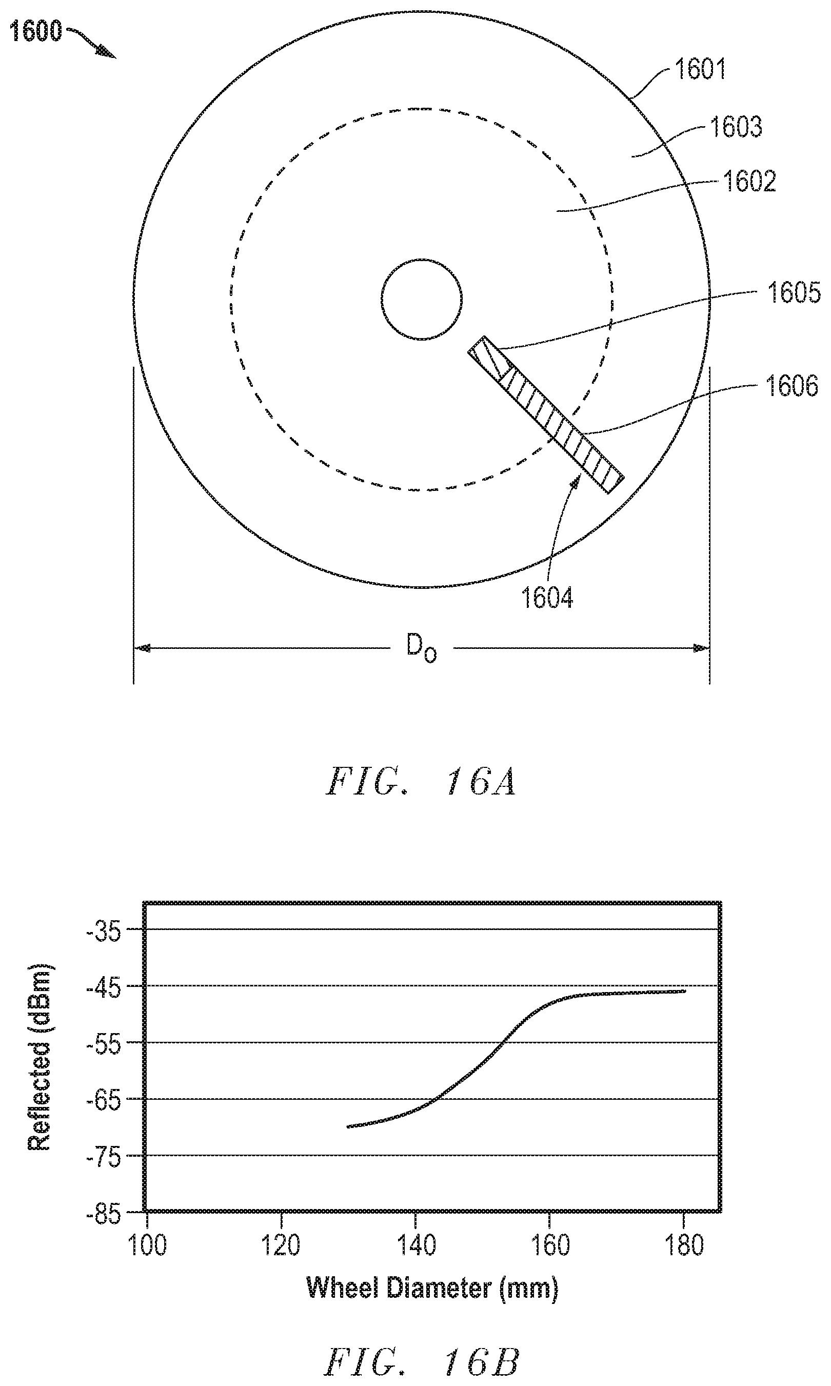
D00015

D00016

D00017
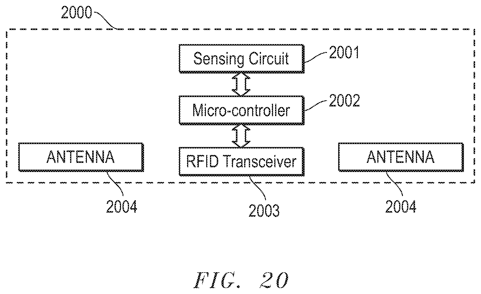
D00018

XML
uspto.report is an independent third-party trademark research tool that is not affiliated, endorsed, or sponsored by the United States Patent and Trademark Office (USPTO) or any other governmental organization. The information provided by uspto.report is based on publicly available data at the time of writing and is intended for informational purposes only.
While we strive to provide accurate and up-to-date information, we do not guarantee the accuracy, completeness, reliability, or suitability of the information displayed on this site. The use of this site is at your own risk. Any reliance you place on such information is therefore strictly at your own risk.
All official trademark data, including owner information, should be verified by visiting the official USPTO website at www.uspto.gov. This site is not intended to replace professional legal advice and should not be used as a substitute for consulting with a legal professional who is knowledgeable about trademark law.