Abrasive Pad
YOKOTA; Nobutoshi ; et al.
U.S. patent application number 16/586545 was filed with the patent office on 2020-02-06 for abrasive pad. This patent application is currently assigned to FURUKAWA ELECTRIC CO., LTD.. The applicant listed for this patent is FURUKAWA ELECTRIC CO., LTD.. Invention is credited to Takashi NARIMATSU, Shota SUGIYAMA, Nobutoshi YOKOTA.
| Application Number | 20200039023 16/586545 |
| Document ID | / |
| Family ID | 63676386 |
| Filed Date | 2020-02-06 |

| United States Patent Application | 20200039023 |
| Kind Code | A1 |
| YOKOTA; Nobutoshi ; et al. | February 6, 2020 |
ABRASIVE PAD
Abstract
An object of the present disclosure is to provide an abrasive pad that is superior in abrading performance and abrasive slurry discharging properties. An abrasive pad having an abrading part and a groove part on an abrasive surface is provided in which a surface of the groove part has a non-foamed part, and a foamed part is exposed on a surface of the abrading part.
| Inventors: | YOKOTA; Nobutoshi; (Tokyo, JP) ; SUGIYAMA; Shota; (Tokyo, JP) ; NARIMATSU; Takashi; (Tokyo, JP) | ||||||||||
| Applicant: |
|
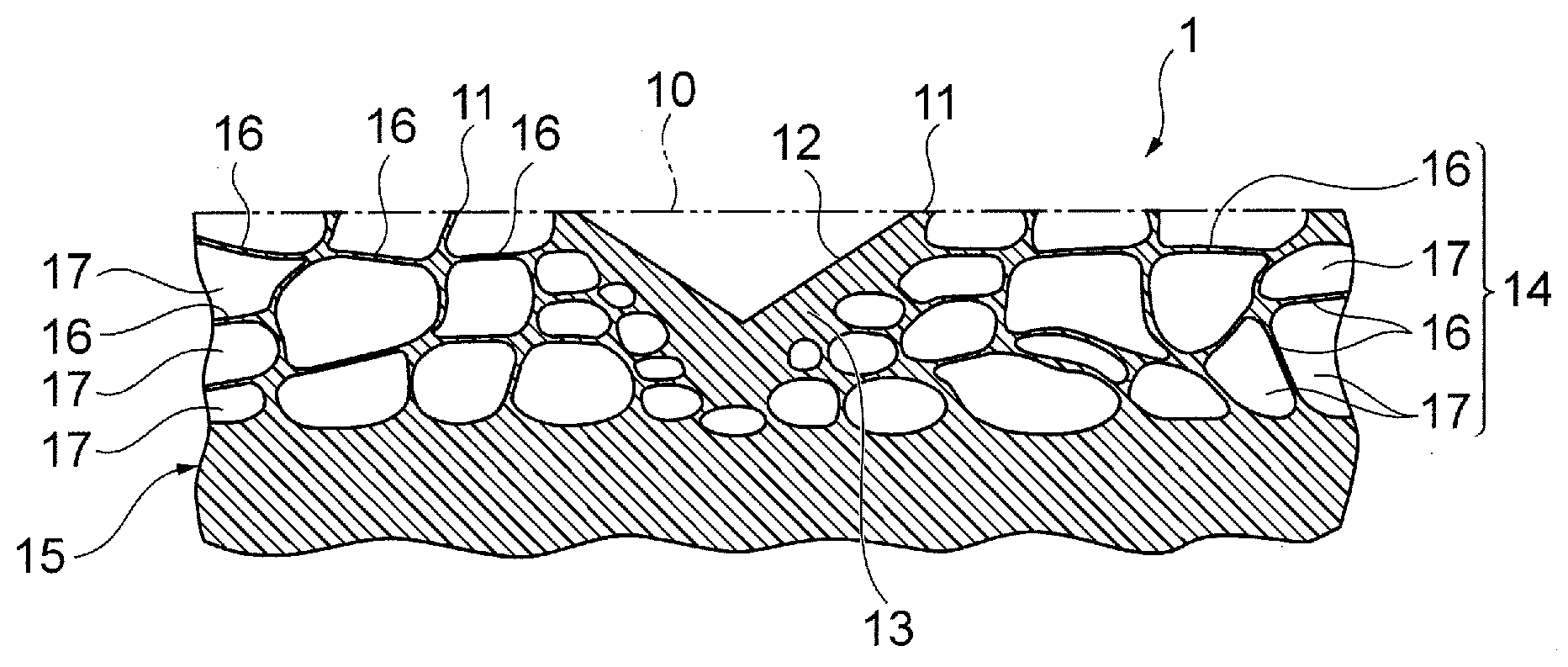
||||||||||
|---|---|---|---|---|---|---|---|---|---|---|---|
| Assignee: | FURUKAWA ELECTRIC CO., LTD. Tokyo JP |
||||||||||
| Family ID: | 63676386 | ||||||||||
| Appl. No.: | 16/586545 | ||||||||||
| Filed: | September 27, 2019 |
Related U.S. Patent Documents
| Application Number | Filing Date | Patent Number | ||
|---|---|---|---|---|
| PCT/JP2018/012483 | Mar 27, 2018 | |||
| 16586545 | ||||
| Current U.S. Class: | 1/1 |
| Current CPC Class: | B24B 37/26 20130101; B24B 37/24 20130101; C08L 67/02 20130101; C08L 69/00 20130101; C08L 81/02 20130101; H01L 21/304 20130101 |
| International Class: | B24B 37/26 20060101 B24B037/26; B24B 37/24 20060101 B24B037/24 |
Foreign Application Data
| Date | Code | Application Number |
|---|---|---|
| Mar 31, 2017 | JP | 2017-070780 |
Claims
1. An abrasive pad comprising an abrading part and a groove part on an abrasive surface, wherein a surface of the groove part comprises a non-foamed part, and a foamed part is exposed on a surface of the abrading part.
2. The abrasive pad according to claim 1, wherein a maximum height roughness (Rz) of the surface of the groove part is 10 .mu.m to 30 .mu.m, and a maximum height roughness (Rz) of the surface of the abrading part is 30 .mu.m to 100 .mu.m.
3. The abrasive pad according to claim 1, wherein an arithmetic mean roughness (Ra) of the surface of the groove part is 0.1 .mu.m to 10 .mu.m, and an arithmetic mean roughness (Ra) of the surface of the abrading part is 10 .mu.m to 45 .mu.m.
4. The abrasive pad according to claims 1, wherein a value of (the maximum height roughness (Rz) of the surface of the abrading part)-(the maximum height roughness (Rz) of the surface of the groove part) is 20 .mu.m to 70 .mu.m.
5. The abrasive pad according to claims 1, wherein a value of (the arithmetic mean roughness (Ra) of the surface of the abrading part)-(the arithmetic mean roughness (Ra) of the surface of the groove part) is 5 .mu.m to 35 .mu.m.
6. The abrasive pad according to claims 1, comprising a resin foam formed from a thermoplastic resin that has a three-dimensional bubble structure, wherein the thermoplastic resin is at least one type of resin selected from a group of polyphenylene sulfide resin, polyethylene terephthalate resin, and polycarbonate resin.
Description
CROSS REFERENCE TO RELATED APPLICATIONS
[0001] The present application is a continuation application of International Patent Application No. PCT/JP2018/012483 filed on Mar. 27, 2018, which claims the benefit of Japanese Patent Application No. 2017-070780, filed on Mar. 31, 2017. The contents of these applications are incorporated herein by reference in their entirety.
BACKGROUND
Technical Field
[0002] The present disclosure relates to an abrasive pad having a superior abrading performance and superior abrasive slurry discharging properties.
Background
[0003] Conventionally, in an abrasion process of a thin plate member such as a magnetic disc that is installed in a hard disc drive (HDD) or a semiconductor wafer, since work generating neither a minute flaw nor a latent flaw on a surface of a processing target object is required, smoothing mirror surface work is performed by use of a non-woven fabric system or foam system abrasive pad while supplying an abrasive slurry containing minute abrasive grains.
[0004] Not only the abradability but also the abrasive slurry discharging properties are required on an abrasive pad for such smoothing mirror surface work. Then, in order to improve the balance between supplying and discharging the abrasive slurry (the abrasive slurry discharging properties), an abrasive pad has been proposed which has an abrasive layer with a groove on an abrasive surface and in which a mean roughness (Ra) on an inner surface of the groove is in a range of 1.0 to 5.0 .mu.m (Japanese Patent Application Laid-Open No. 2006-186239).
[0005] In the abrasive pad of Japanese Patent Application Laid-Open No. 2006-186239, however, since the groove is formed on a porous material through cutting, and the inner surface of the groove is formed into a non-porous surface by after-working such as laser melting, the work becomes complex. In addition, nothing is specified about the state (in particular, roughness) of the abrasive surface of the abrasive layer, and thus, the abrasive pad causes a problem in that the abradability may not be compatible with the abrasive slurry discharging properties, resulting in a problem in that superior smoothing mirror surface work cannot be performed.
SUMMARY
[0006] The present disclosure is related to providing an abrasive pad having a superior abrading performance and superior abrasive slurry discharging properties.
[0007] According to a first aspect of the present disclosure, an abrasive pad is provided which has an abrading part and a groove part on an abrasive surface, and a surface of the groove part has a non-foamed part, and a foamed part is exposed on a surface of the abrading part.
[0008] In the abrasive pad according to the first aspect, the abrasive surface has the abrading part configured to abrade a processing target object which is an abrasion target and the groove part configured to discharge an abrasive slurry supplied to the abrasive pad when the processing target object is abraded from the abrasive pad to an exterior of the abrasive pad. Since the foamed part of the foam is exposed on the surface of the abrading part and the surface of the groove part has the non-foamed part, a form results in which a maximum height roughness (Rz) of the surface of the abrading part is greater than a maximum height roughness (Rz) of the surface of the groove part, and an arithmetic mean roughness (Ra) of the surface of the abrading part is greater than an arithmetic mean roughness (Ra) of the surface of the groove part.
[0009] According to a second aspect of the present disclosure, in the abrasive pad, the maximum height roughness (Rz) of the surface of the groove part is 10 .mu.m to 30 .mu.m, and the maximum height roughness (Rz) of the surface of the abrading part is 30 .mu.m to 100 .mu.m.
[0010] According to a third aspect of the present disclosure, in the abrasive pad, the arithmetic mean roughness (Ra) of the surface of the groove part is 0.1 .mu.m to 10 .mu.m, and the arithmetic mean roughness (Ra) of the surface of the abrading part is 10 .mu.m to 45 .mu.m.
[0011] According to a fourth aspect of the present disclosure, in the abrasive pad, a value of (the maximum height roughness (Rz) of the surface of the abrading part)-(the maximum height roughness (Rz) of the surface of the groove part) is 20 .mu.m to 70 .mu.m.
[0012] According to a fifth aspect of the present disclosure, in the abrasive pad, a value of (the arithmetic mean roughness (Ra) of the surface of the abrading part)-(the arithmetic mean roughness (Ra) of the surface of the groove part) is 5 .mu.m to 35 .mu.m.
[0013] According to a sixth aspect of the present disclosure, the abrasive pad has a resin foam formed from a thermoplastic resin that has a three-dimensional bubble structure, wherein
[0014] the thermoplastic resin is at least one type of resin selected from a group of polyphenylene sulfide resin, polyethylene terephthalate resin, and polycarbonate resin.
[0015] According to the aspects of the present disclosure, the abrasive slurry can be discharged smoothly from the abrasive pad due to the surface of the groove part having the non-foamed part. Consequently, abrasion dust (abrasion residue) that is mixed with the abrasive slurry through the abrasion process can be prevented from staying on the abrasive pad. Additionally, since the abrasive slurry can be discharged smoothly from the abrasive pad, an increase in the temperature of the abrasive pad can be prevented. On the other hand, since the foamed part is exposed on the surface of the abrading part, that is, the surface of the abrading part is rough, the abrading performance of the abrading part is improved, and the abrading performance of the abrading part is also increased by the abrasive slurry being captured by the exposed foamed part.
BRIEF DESCRIPTION OF THE DRAWINGS
[0016] FIG. 1 is a partial side sectional view of an abrasive pad according to an embodiment of the present disclosure.
[0017] FIG. 2 is a partial side sectional view of a resin member for use for an example of an abrasive pad production method according to the embodiment of the present disclosure.
[0018] FIG. 3A is an overall explanatory drawing of a groove part forming die member for use for the example of the abrasive pad production method according to the embodiment of the present disclosure, and FIG. 3B is a cross-sectional view of the groove part forming die member taken along a line A-A.
[0019] FIG. 4 is an explanatory drawing of the example of the abrasive pad production method according to the embodiment of the present disclosure using the groove part forming die member.
DETAILED DESCRIPTION
[0020] Hereinafter, an abrasive pad according to an embodiment of the present disclosure will be described with reference to the accompanying drawings.
[0021] As illustrated in FIG. 1, in an abrasive pad 1 according to the embodiment of the present disclosure, an abrasive surface 10, which is a surface on an abrading side, has an abrading part 11 and a groove part 12. The abrading part 11 is a part configured to abrade a processing target object (not shown), which is an abrasion target. The groove part 12 is a part configured to discharge abrasive slurry that is supplied to the abrasive pad when abrading the processing target object and abrasion dusts from the abrasive surface 10 to an exterior.
[0022] The abrasive pad 1 includes a resin foam 15 having a surface non-foamed layer 13, whose surface constitutes a non-foamed part, and a foamed part 14 provided in an interior of the surface non-foamed layer 13. In the abrasive pad 1, the foamed part 14 of the resin foam 15 is exposed over substantially an overall surface of the abrading part 11. Consequently, in the abrasive pad 1, a surface of the abrading part 11 does not have the surface non-foamed layer 13.
[0023] The foamed part 14 of the resin foam 15 constitutes a three-dimensional bubble structure in which a plurality of bubbles 17 divided by bubble walls 16 are formed densely. Since the three-dimensional bubble structure is exposed from the surface at the abrading part 11, a form results in which inner surfaces of the bubbles 17 are exposed on the surface of the abrading part 11. Consequently, the surface of the abrading part 11 is of a porous structure. At the abrading part 11, the foamed part 14 can be exposed by removing the surface non-foamed layer 13 in advance through an abrasion process or the like.
[0024] On the other hand, a surface of the groove part 12 has a non-foamed part of the resin foam 15. That is, the surface of the groove part 12 constitutes the surface non-foamed layer 13. Bubbles, which are to be formed through a foaming process, are not formed in the surface non-foamed layer 13. In the abrasive pad, substantially an overall area of the surface of the groove part 12 constitutes the surface non-foamed layer 13, which is the non-foamed part. Consequently, interiors of the bubbles 17, that is, inner surfaces of the bubble walls 16 are not exposed from the surface of the groove part 12, and hence, a porous structure is not exposed.
[0025] From what has been described above, the surface of the groove part 12, which constitutes the surface non-foamed layer 13, is smooth, and the surface of the abrading part 11, from which the foamed part 14 is exposed, is rougher than the surface of the groove part 12. That is, the surface of the abrading part 11 takes greater values for both a maximum height roughness (Rz) and an arithmetic mean roughness (Ra) than those of the surface of the groove part 12. In the present description, the "maximum height roughness (Rz)" and the "arithmetic mean roughness (Ra)" mean values measured with a laser microscope (VX-X150, made by KEYENCE CORPORATION).
[0026] Although the maximum height roughness (Rz) of the surface of the abrading part 11 is not particularly limited, it is preferable that a lower limit value of the maximum height roughness (Rz) is, for example, 20 .mu.m or greater from the viewpoint of improving the abrading performance of the abrading part 11 due to the roughness of the surface, is more preferable that the lower limit value is 25 .mu.m or greater from the viewpoint of further improving the abrading performance of the abrading part 11 as a result of the abrasive slurry being captured on the inner surface of the bubble walls 16 of the foamed part 14 that is exposed, and is most preferable that the lower limit value is 30 .mu.m or greater. On the other hand, it is preferable that an upper limit value of the maximum height roughness (Rz) of the surface of the abrading part 11 is, for example, 100 .mu.m or smaller from the viewpoint of facilitating the production of the resin foam 15, is more preferable that the upper limit value is 65 .mu.m or smaller, and is most preferable that the upper limit value is 55 .mu.m or smaller.
[0027] Although the arithmetic mean roughness (Ra) of the surface of the abrading part 11 is not particularly limited, it is preferable that a lower limit value of the arithmetic mean roughness (Ra) is, for example, 10 .mu.m or greater from the viewpoint of improving the abrading performance of the abrading part 11 due to the roughness of the surface, is more preferable that the lower limit value is 15 .mu.m or greater from the viewpoint of further improving the abrading performance of the abrading part 11 as a result of the abrasive slurry being captured on the inner surface of the bubble walls 16 of the foamed part 14 that is exposed, and is most preferable that the lower limit value is 25 .mu.m or greater. On the other hand, it is preferable that an upper limit value of the arithmetic mean roughness (Ra) of the surface of the abrading part 11 is, for example, 45 .mu.m or smaller from the viewpoint of facilitating the production of the resin foam 15, and is particularly preferable that the upper limit value is 35 .mu.m or smaller.
[0028] Although the maximum height roughness (Rz) of the surface of the groove part 12 is not particularly limited, it is preferable that a lower limit value of the maximum height roughness (Rz) is, for example, 10 .mu.m or greater from the viewpoint of facilitating the production of the resin foam 15, and is particularly preferable that the lower limit value is 15 .mu.m or greater. On the other hand, it is preferable that an upper limit value of the maximum height roughness (Rz) is, for example, 30 .mu.m or smaller from the viewpoint of discharging the abrasive slurry from the abrasive pad smoothly to prevent abrasion dust that is mixed into the abrasive slurry through an abrasion process performed on the processing target object from staying on the abrasive pad in an ensured fashion, is more preferable that the upper limit value is 25 .mu.m or smaller from the viewpoint of discharging the abrasive slurry from the abrasive pad smoothly to thereby prevent the temperature of the abrasive pad from increasing in an ensured fashion, and is most preferable that the upper limit value is 20 .mu.m or smaller.
[0029] Although the arithmetic mean roughness (Ra) of the surface of the groove part 12 is not particularly limited, it is preferable that a lower limit value of the arithmetic mean roughness (Ra) is, for example, 0.1 .mu.m or greater from the viewpoint of facilitating the production of the resin foam 15, and is particularly preferable that the lower limit value is 0.5 .mu.m or greater. On the other hand, it is preferable that an upper limit value of the arithmetic mean roughness (Ra) is, for example, 10 .mu.m or smaller from the viewpoint of discharging the abrasive slurry from the abrasive pad smoothly to prevent abrasion dust that is mixed into the abrasive slurry through an abrasion process performed on the processing target object from staying on the abrasive pad in an ensured fashion, is more preferable that the upper limit value is 5 .mu.m or smaller from the viewpoint of discharging the abrasive slurry from the abrasive pad smoothly to thereby prevent the temperature of the abrasive pad from increasing in an ensured fashion, and is most preferable that the upper limit value is 3 .mu.m or smaller.
[0030] Although a value of (the maximum height roughness (Rz) of the surface of the abrading part 11)-(the maximum height roughness (Rz) of the surface of the groove part 12), that is, a difference between the maximum height roughness (Rz) of the surface of the abrading part 11 and the maximum height roughness (Rz) of the surface of the groove part 12 is not particularly limited, it is preferable that a lower limit value of the difference between the maximum height roughness (Rz) of the surface of the abrading part 11 and the maximum height roughness (Rz) of the surface of the groove part 12 is, for example, 20 .mu.m or greater from the viewpoint of improving the balance between the abrading performance and the discharging properties of the abrasive slurry, and is particularly preferable that the lower limit value is 30 .mu.m or greater. On the other hand, although an upper limit value of the difference between the maximum height roughness (Rz) of the surface of the abrading part 11 and the maximum height roughness (Rz) of the surface of the groove part 12 is not particularly limited to any value, it is preferable that the upper limit value is 70 .mu.m or smaller from the viewpoint of facilitating the production of the resin foam 15, and is particularly preferable that the upper limit value is 60 .mu.m or smaller.
[0031] Although a value of (the arithmetic mean roughness (Ra) of the surface of the abrading part 11)-(the arithmetic mean roughness (Ra) of the surface of the groove part 12), that is, a difference between the arithmetic mean roughness (Ra) of the surface of the abrading part 11 and the arithmetic mean roughness (Ra) of the surface of the groove part 12 is not particularly limited, it is preferable that a lower limit value of the difference between the arithmetic mean roughness (Ra) of the surface of the abrading part 11 and the arithmetic mean roughness (Ra) of the surface of the groove part 12 is, for example, 5 .mu.m or greater from the viewpoint of improving the balance between the abrading performance and the discharging properties of the abrasive slurry, and is particularly preferable that the lower limit value is 10 .mu.m or greater. On the other hand, although an upper limit value of the difference between the arithmetic mean roughness (Ra) of the surface of the abrading part 11 and the arithmetic mean roughness (Ra) of the surface of the groove part 12 is not particularly limited to any value, it is preferable that the upper limit value is 35 .mu.m or smaller from the viewpoint of facilitating the production of the resin foam 15, and is particularly preferable that the upper limit value is 30 .mu.m or smaller.
[0032] Although the material of the resin foam 15 is not particularly limited, the material may be hard resin such as polyphenylene sulfide resin (PPS resin), polyethylene terephthalate (PET rein), and polycarbonate resin (PC resin) for example.
[0033] Although the thickness of the resin foam 15 provided on the abrasive pad 1 is not particularly limited, the thickness may be in a range of about 0.5 to 2.0 mm for example, and in the abrasive pad 1, the thickness of the resin foam 15 may be about 1.0 mm, for example. Additionally, although the depth of the groove part 12 is not particularly limited, the depth may be in a range of about 0.2 to 1.0 mm for example, and in the abrasive pad 1, the depth of the groove part 12 may be about 0.5 mm, for example.
[0034] The resin foam 15 has a three-dimensional cell structure that is made up of a plurality of bubbles (cells) that are divided by bubble walls so that the cells are divided independently of one another. Although an average bubble diameter is not particularly limited, it is preferable that the average bubble diameter is, for example, 4 to 50 .mu.m, and although an average bubble wall thickness is not particularly limited, it is preferable that the average bubble wall thickness is, for example, 1 to 5 .mu.m. Here, the bubble diameter is a diameter when a bubble in an arbitrary cross section is converted to a circle of the same area, and the average bubble diameter is an average diameter of 10 bubbles that are selected arbitrarily. In addition, the bubble wall thickness is a minimum thickness of a bubble wall between bubbles that lie adjacent to each other in an arbitrary cross section, and the average bubble wall thickness is an average of bubble wall thicknesses at 10 locations that are selected arbitrarily. The average bubble diameter and the average bubble wall thickness can be obtained by image processing a photograph of the structure of the resin foam 15 observed with a scanning electronic microscope (SEM, made by JEOL Ltd.).
[0035] When the average bubble diameter is smaller than 4 .mu.m, the number of abrasive grains held in the interior of a bubble is reduced, and the abrading speed is reduced, whereby a stable abrasive surface cannot be obtained, whereas when the average bubble diameter exceeds 50 .mu.m, the strength of the bubble wall becomes insufficient, and a stable abrading condition cannot be obtained, which reduces the surface quality and at the same time causes a large number of abrasive particles to be accumulated within the bubble, producing secondary particles to facilitate the generation of a surface defect such as a scratch. The bubble structure is optimized, and the abrading speed becomes superior by causing the average bubble diameter to stay within the range defined therebetween.
[0036] In addition, it is preferable that a ratio of the average bubble diameter to the average bubble wall thickness is 4 or greater and 10 or smaller. When the ratio of the average bubble diameter and the average bubble wall thickness is smaller than 4, the number of abrasive grains as abrasive particles held in the interior of the bubble is reduced, whereby the abrading speed is reduced, and a stable abrasive surface cannot be obtained, whereas when the ratio of the average bubble diameter and the average bubble wall thickness exceeds 10, the strength of the bubble wall becomes insufficient, whereby the stable abrading condition cannot be obtained, and the abrading speed is reduced.
[0037] Next, an example of a production method of the abrasive pad 1 according to the embodiment of the present disclosure will be described by reference to the accompanying drawings.
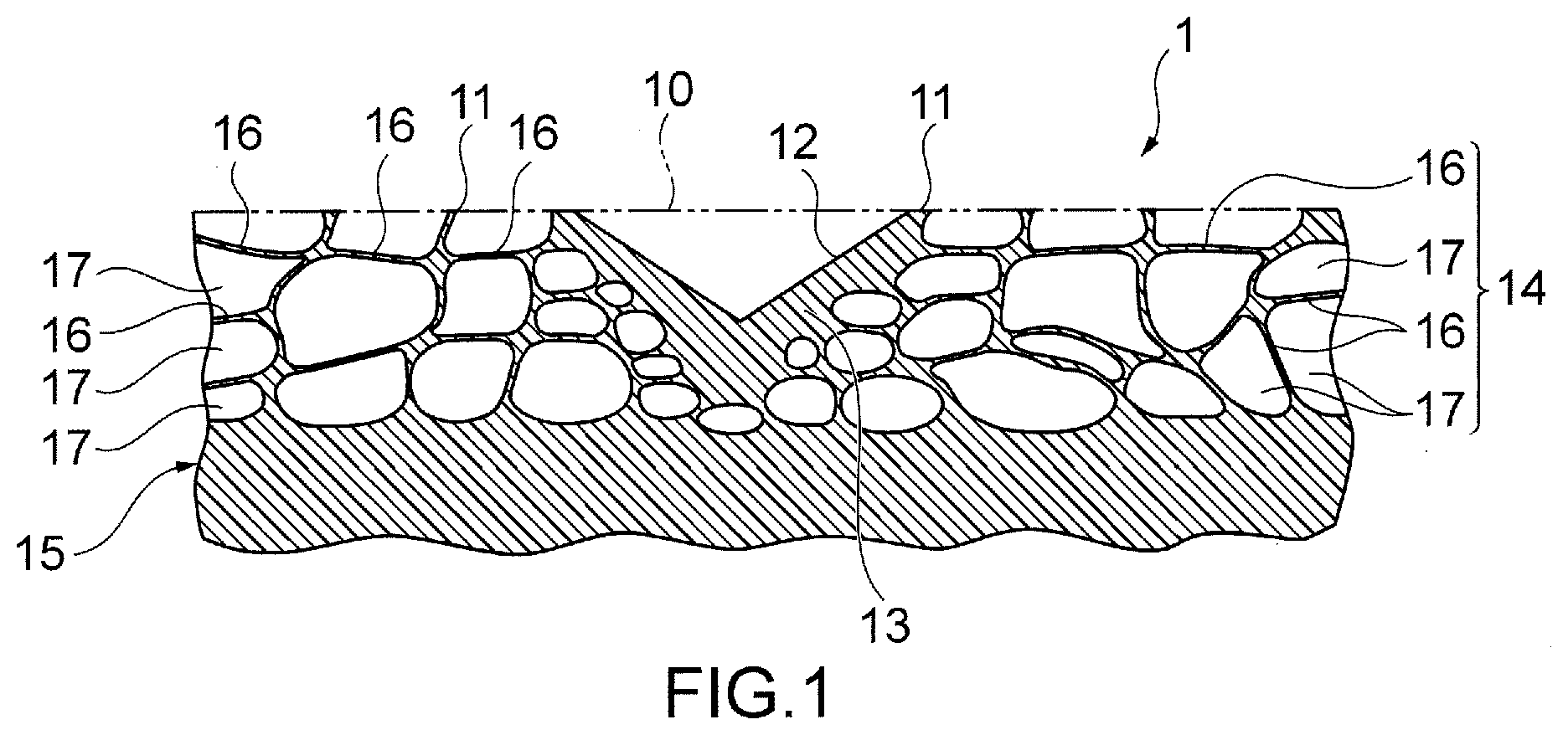
[0038] As illustrated in FIG. 2, in producing the abrasive pad 1, a resin member 20 having a flat plate-like shape that includes a surface non-foamed layer 13 in which a surface layer is made up of a non-foamed part and a foamed part 14 provided in an interior of the surface non-foamed layer 13 is used. One of flat surfaces where the surface non-foamed layer 13 is provided constitutes a surface on an abrading side of the abrasive pad 1. Consequently, an outer surface of the surface non-foamed layer 13 of the resin member 20 becomes substantially flat. The thickness of the resin member 20 is the thickness of the resin foam 15 described above, and although the thickness of the surface non-foamed layer 13 of the resin member 20 is not particularly limited, the thickness may be in a range of about 25 to 100 .mu.m for example, and in the resin member 20, the thickness of the surface non-foamed layer 13 may be about 50 .mu.m, for example. The thickness of the foamed part 14 of the resin member 20 is a thickness resulting from subtracting the thickness of the surface non-foamed layer 13 on a front surface and a rear surface of the resin member 20 from the thickness of the resin member 20.
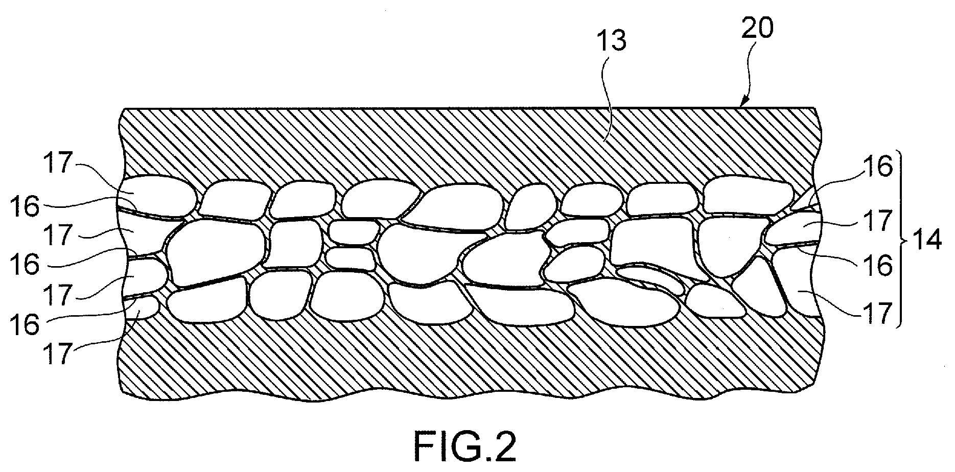
[0039] Firstly, groove parts 12 are formed on the surface non-foamed layer 13 of the resin member 20 described above. As a forming method of the groove part 12, for example, as illustrated in FIGS. 3A and 3B, a method using a groove part forming die member 21 having blade-like projecting parts 22 may be selected. The groove part forming die member 21 has a thin plate-like shape. Although an arrangement of the projecting parts 22 of the groove part forming die member 21 is not particularly limited, in FIG. 3A, a plurality of projecting parts 22 are formed concentrically and at substantially equal intervals. In addition, although a cross-sectional shape of the projecting part 22 is not particularly limited, as illustrated in FIG. 3B, in the groove part forming die member 21, the cross-sectional shape of the projecting part 22 has a substantially triangular shape.
[0040] The groove part forming die member 21 is pressed against the resin member 20 in FIG. 2, and apex portions of the projecting parts 22 of the groove part forming die member 21 are pressed against the surface non-foamed layer 13 of the resin member 20 at a predetermined pressure, this allowing the surface non-foamed layer 13 to be pushed towards the foamed part 14, whereby groove parts 12 can be formed on the abrasive pad 1. Consequently, the groove parts 12 are formed on the surface non-foamed layer 13 of the resin member 20 in positions corresponding to positions of the projecting parts 22 on the groove part forming die member 21 in FIGS. 3A and 3B. A depth of the groove part 12 is defined according to a height of the projecting part 22. Consequently, the height of the projecting part 22 can be selected as required according to a desired depth of the groove part 12. For example, a range of about 0.2 to 1.0 mm may be selected, and in the groove part forming die member 21 for producing the abrasive pad 1, the height of the projecting part 22 may be about 0.5 mm, for example. As a material for the groove part forming die member 21, the material may be metal or hard resin, for example.
[0041] As a method for pressing the groove part forming die member 21 against the resin member 20, for example, as illustrated in FIG. 4, the groove part forming die member 21 is given a roller-like shape, and the projecting parts 22 are pressed against the surface non-foamed layer 13 of the resin member 20 at the predetermined pressure while the groove part forming die member 21 having the roller-like shape is being rotated, whereby the groove parts 12 can be formed on the resin member 20.
[0042] On the surface on the abrading side of the resin member 20 where the groove parts 12 are formed, locations other than the groove parts 12 function as the abrading part 11. The foamed parts 14 of the resin member 20 are exposed to function as the abrading part 11 by removing the surface non-foamed layer 13 at the other locations than the groove parts 12 through an abrasion process such as a buff abrasion, whereby the resin member 20 can be formed as the abrasive pad 1.
[0043] Although a thickness of the resin foam 15 including the surface non-foamed layer 13 that is removed by the buff abrasion or the like is not particularly limited, for example, a thickness in the range of about 50 to 200 .mu.m may be removed, and in the abrasive pad 1 according to the embodiment, since the thickness of the surface non-foamed layer 13 of the resin member 20 is about 50 .mu.m, a form results in which about 100 .mu.m is removed from the resin member 20.
[0044] In the example of the production method of the abrasive pad 1 described above, since the groove parts 12 whose surfaces are smooth can be formed by pressing the projecting parts 22 having the blade-like shape against the resin member 20 having the surface non-foamed layer 13 and the foamed parts 14, the production of the abrasive pad 1 is easy. In addition, since the groove parts 12 can be formed by pressing the projecting parts 22 against the resin member 20, the shape and arrangement of the groove parts 12 can be changed by changing the shape and arrangement of the projecting parts 22, thereby making it possible to improve the degree of freedom in designing the groove parts 12.
[0045] The production method of the resin member 20 having the surface non-foamed layer 13 and the foamed parts 14 is not particularly limited, and hence, the known methods can be used. For example, a method for producing the resin member 20 having the surface non-foamed layer 13 and the foamed parts 14 may be a method in which a formed product of predetermined non-foamed resin is sealed in a high pressure container, and inactive gas is injected into this high pressure container, whereby the inactive gas is penetrated into the formed product under pressure. In the method, after the penetration of the inactive gas into the formed product, the pressure in the pressure container is released, and then, the formed product is heated to be foamed, after which the formed product is cooled, whereby the resin member 20 having the surface non-foamed layer 13 and the foamed parts 14 is produced. Alternatively, the foaming characteristics of the individual resin layers can be controlled to some extent by adding a foaming nucleating agent to a thermoplastic resin layer for forming a foamed layer or adding in advance a crystallization nucleating agent and a crystallization promoting agent to a thermoplastic resin layer for forming a non-foamed layer. Additionally, the foaming characteristics can be controlled further strictly by adopting a specific resin as a thermoplastic resin for use in forming each layer. The dimension of the bubble 17, the dimension of the bubble wall 16, and the density at which the bubbles 17 are provided are controlled by appropriately controlling the foaming conditions described above, whereby the maximum height roughness (Rz) and the arithmetic mean roughness (Ra) of the abrading part 11 can be controlled.
[0046] The abrasive pad according to the embodiment of the present disclosure can be applied, for example, to an abrading device for abrading a magnetic disc, a semiconductor wafer, various types of substrates, and electronic materials. As the abrading device, for example, the abrading device may be one which includes a lower surface plate on an inner surface of which an abrasive pad is disposed, a support member for supporting a processing target object such as a semiconductor wafer on the abrasive pad on the lower surface plate, an upper surface plate on an inner surface of which an abrasive pad is disposed for applying a predetermined pressure to the processing target object such as the semiconductor wafer, and an abrasive slurry supply unit.
[0047] Next, another embodiment of an abrasive pad of the present disclosure will be described. In the abrasive pad 1 according to the embodiment described above, while the foamed parts 14 are exposed on the overall surface of the abrading part 11 and the abrading part 11 does not have the surface non-foamed layer 13, in place of this form, a form may be adopted in which in an abrading part 11, foamed parts 14 are exposed on a partial surface, and the other surfaces constitute a surface non-foamed layer 13.
[0048] In the groove part forming die member described above, while the cross section of the projecting part has the substantially triangular shape, the cross-sectional shape of the projecting part is not limited to the shape described as long as the projecting parts project, and hence, in place of the triangular shape, for example, a polygonal shape may be used which includes a quadrangular shape such as a trapezoid, or a pentagonal shape, a substantially semi-oval shape, a substantially semicircular shape, and the like.
[0049] Since the abrasive pad of the present disclosure is superior in the abrading performance and the abrasive slurry discharging properties, the abrasive pad can be made use of in a variety of fields, and the abrasive pad of the present disclosure has a high utilization quality in the field of abrading a magnetic disc and a semiconductor wafer where a high-degree smoothing mirror surface work is required.
* * * * *
D00000
D00001
D00002
D00003
D00004
XML
uspto.report is an independent third-party trademark research tool that is not affiliated, endorsed, or sponsored by the United States Patent and Trademark Office (USPTO) or any other governmental organization. The information provided by uspto.report is based on publicly available data at the time of writing and is intended for informational purposes only.
While we strive to provide accurate and up-to-date information, we do not guarantee the accuracy, completeness, reliability, or suitability of the information displayed on this site. The use of this site is at your own risk. Any reliance you place on such information is therefore strictly at your own risk.
All official trademark data, including owner information, should be verified by visiting the official USPTO website at www.uspto.gov. This site is not intended to replace professional legal advice and should not be used as a substitute for consulting with a legal professional who is knowledgeable about trademark law.