Bar Press With Hydraulic Drive
Wershofen-Crombach; Andreas ; et al.
U.S. patent application number 16/598590 was filed with the patent office on 2020-02-06 for bar press with hydraulic drive. The applicant listed for this patent is SMS Group GmbH. Invention is credited to Stephan Frehe, Ewald Hagen, Andreas Wershofen-Crombach.
| Application Number | 20200038928 16/598590 |
| Document ID | / |
| Family ID | 69229518 |
| Filed Date | 2020-02-06 |


View All Diagrams
| United States Patent Application | 20200038928 |
| Kind Code | A1 |
| Wershofen-Crombach; Andreas ; et al. | February 6, 2020 |
BAR PRESS WITH HYDRAULIC DRIVE
Abstract
A bar and tube extruding press for thrilling metal ingots into profiles, tubes, bars or the like includes a male die and a female die, through which a metal ingot can be pressed by the male die a container, and a driving device, in which the driving device has at least one main cylinder tor applying the main pressing force of the male die to the metal ingots, characterized in that on the one hand the driving device having at least one speed-controlled internal gear pump for providing the hydraulic oil to the at least one main cylinder, with which the at least one main cylinder can be driven, and at least one hydraulic advance and/or return cylinder for moving the male die in relation to the female die or at least one electrical drive for moving the male die in relation to the female die and with which the male die can be moved into a position in which the speed-controlled internal gear pump only then interacts with the at least one main cylinder in such a way that the main pressing force is applied to the male die by the at least one main cylinder.
| Inventors: | Wershofen-Crombach; Andreas; (Monchengladbach, DE) ; Hagen; Ewald; (Vreden, DE) ; Frehe; Stephan; (Erkrath, DE) | ||||||||||
| Applicant: |
|
||||||||||
|---|---|---|---|---|---|---|---|---|---|---|---|
| Family ID: | 69229518 | ||||||||||
| Appl. No.: | 16/598590 | ||||||||||
| Filed: | October 10, 2019 |
Related U.S. Patent Documents
| Application Number | Filing Date | Patent Number | ||
|---|---|---|---|---|
| 16559178 | Sep 3, 2019 | |||
| 16598590 | ||||
| 15311894 | Jan 10, 2017 | |||
| PCT/EP2015/061270 | May 21, 2015 | |||
| 16559178 | ||||
| Current U.S. Class: | 1/1 |
| Current CPC Class: | B21C 23/211 20130101; B21C 23/08 20130101 |
| International Class: | B21C 23/21 20060101 B21C023/21 |
Foreign Application Data
| Date | Code | Application Number |
|---|---|---|
| May 21, 2014 | DE | 102014209685.5 |
Claims
1. A bar and tube extruding press for forming metal ingots into profiles, tubes, billets, or the like, comprising a male die and a female die, through which a metal ingot can be pressed by means of the male die, comprising a ingot container, and comprising a driving device, in which the driving device comprises at least one main cylinder for applying the main pressing force of the male die to the metal ingots, characterized in that the driving device on the one hand includes at least one speed-controlled internal gear pump for supplying hydraulic oil to the at least one main cylinder with which the at least one cylinder can be driven, and on the other hand the driving device additionally comprises at least one hydraulic advance and/or return cylinder for moving the male die in relation to the female die or at least one electrical drive for moving the male die in relation to the female die, by means of which the male die can be moved into a position in which the speed-controlled internal gear pump only then interacts with the at least one main cylinder in such a way that the main pressing three is applied to the male die by means of the at least one main cylinder.
2. The bar and tube extruding press according to claim 1, characterized in that the driving device includes means for moving the male die and/or the ingot container and/or the female die and means for applying a pressing three between the female die and the male die.
3. The bar and tube extruding press according to claim 1, characterized in that the at least one electric drive preferably is an electric servo drive for moving the male die in relation to the female die.
4. The bar and tube extruding press according to claim 1, characterized in that the internal gear pump can be driven using mixed friction from startup until the desired system pressure is reached.
5. The bar and tube extruding press according to claim 1, characterized in that the driving device is connected to a control unit in which a characteristic curve or a plurality of characteristic curves for the internal gear pump and/or its drive motor(s) is/are stored.
6. The bar and tube extruding press according to claim 1, characterized in that the pulsation of the internal gear pump, particularly the preferred internal gear pump, is lower than in axial piston pumps, preferably by at least 20%, preferably by at least 30%, compared to the pulsation of conventional axial piston pumps.
7. A method of forming metal ingots into profiles, tubes, billets, and the like on a bar and tube extruding press having an ingot container, a male die and female die through which a metal ingot is pressed by the male die, a driving device including at least one main cylinder, at least one speed-controlled internal gear pump for supplying oil to the at least one main cylinder, at least one speed-controlled internal gear pump for supplying oil to the at least one main cylinder, and one of the at least one hydraulic advance/return cylinder and at least one electrical drive tor moving the male die relative the female die, the method comprising the steps of: actuating the one of the at least one hydraulic advance/return cylinder and the at least one electrical drive for moving the male die is a predetermined position relative to the female die; and thereafter, actuating the at least one speed-controlled internal gear pump for supplying oil to the at least one main cylinder that applies a main pressing force to the mail die for pressing the ingot through the male and female dies.
8. The method of claim 7, wherein the at least one electrical drive is used for moving the mail die, and the method further comprising the step of forming the electrical drive as an electric servo drive.
9. The method of claim 7, comprising the step of driving the speed-controlled internal gear pump using mixed friction from startup until a desired system pressure is reached.
10. The method of claim 7, comprising the step of selecting pulsation of the speed-controlled internal gear pump so that it is lower than pulsation of a conventional axial piston pump by at least 20%.
11. The method of claim 10, wherein the pulsation selecting step includes selection of the pulsation of the speed-controlled internal gear pump which is lower than the pulsation of the conventional gear pump by at least 30%.
Description
RELATED APPLICATIONS
[0001] This application is a continuation-in-part application of U.S. application Ser. No. 16/559,178 filed Sep. 3, 2019 which is a continuation application of U.S. application Ser. No. 15/311,894 filed Nov. 17, 2016 which is a National Stage application of International Application PCT/EP2015/061270 filed May 21, 2015 and which claims priority of German application DE 10 2014 209 685.5 filed May 21, 2014, all of the applications are incorporated herein by reference thereto.
BACKGROUND OF THE INVENTION
1. Field of the Invention
[0002] The invention relates to a bar and tube extruding press for forming metal ingots into profiles, tubes, billets, or the like, comprising a male die and a female die, through which a metal ingot can be pressed by means of the male die, comprising a ingot container, and comprising a driving device, in which the driving device comprises at least one main cylinder for applying the main pressing force of the male die to the metal ingots.
2. Prior Art
[0003] Such bar and tube extruding presses have been known for decades in prior art and are used for producing the most varied components from typically metallic materials, which are pressed through a female die and subjected to forming at a high degree of deformation.
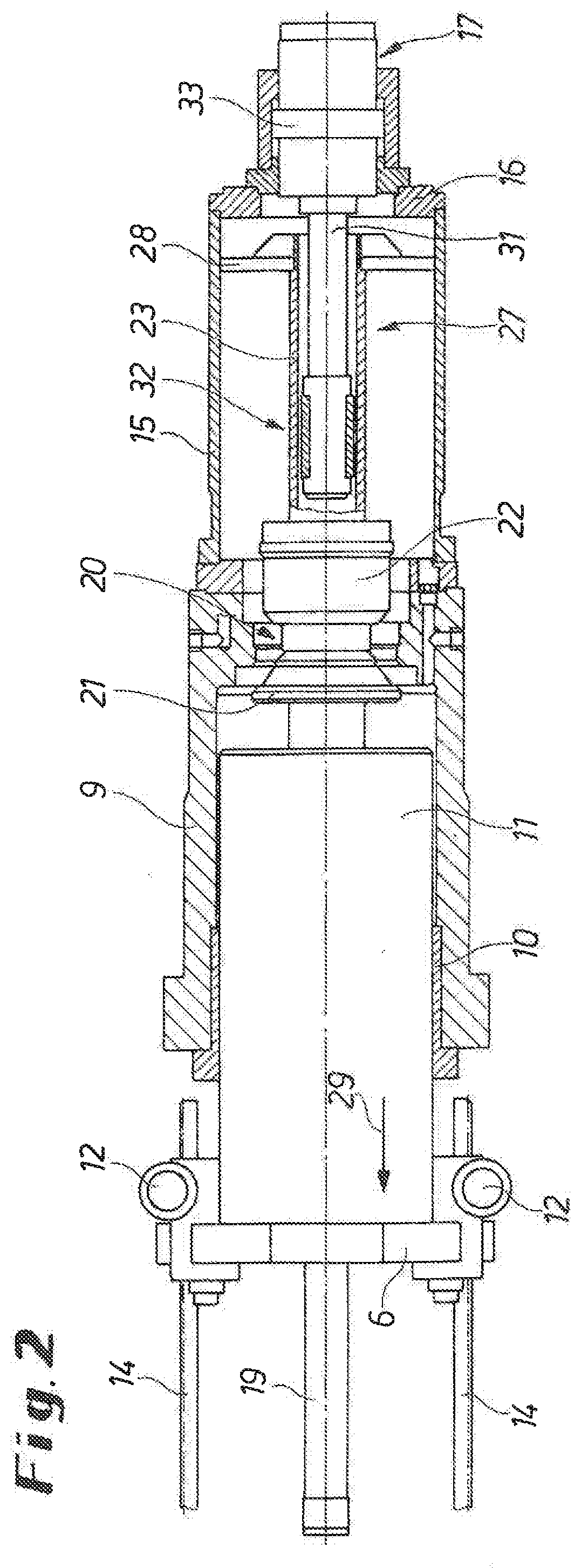
[0004] Main features of conventional bar extruding presses are an ingot loader between the male die and the ingot container and the generation of pressing force using a main cylinder and an advance and/or return cylinder, wherein all auxiliary movements, including the adjustment of the bar extruding press to various ingot formats and feeding the metal ingots to the female die, are performed by hydraulic cylinders. The size of the hydraulic drive is determined by the pressing force to be applied by the bar and tube extruding press and optionally by the pressing speed required for the desired forming process.
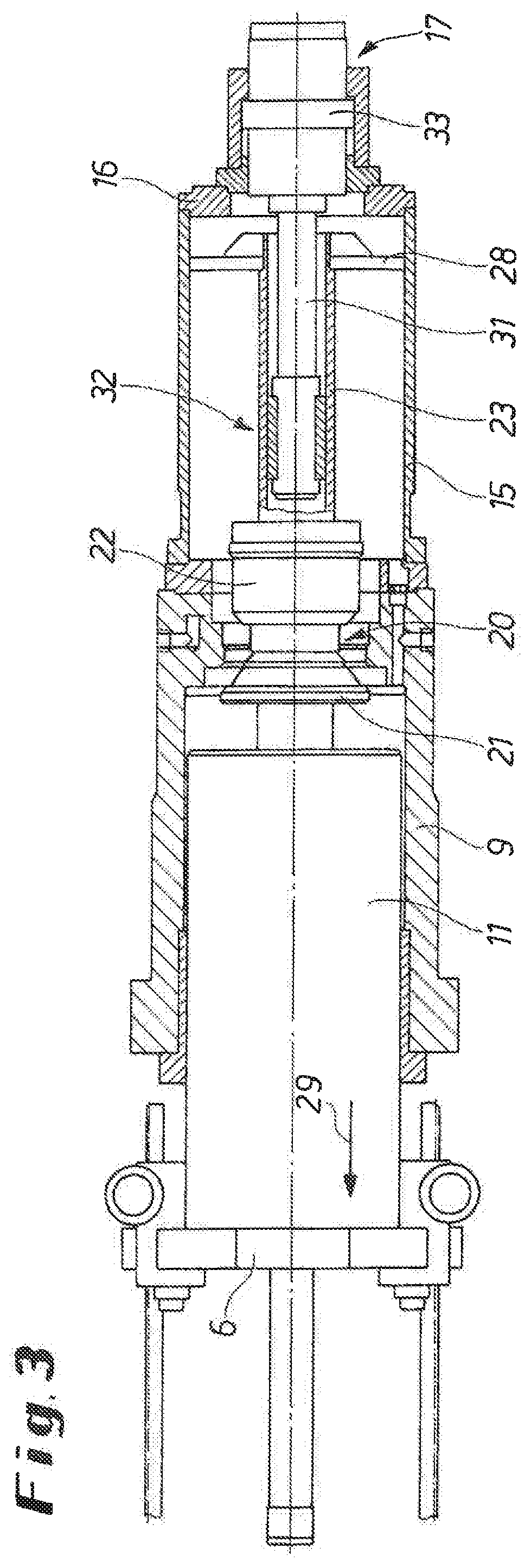
[0005] In the past decades, the known bar and tube extruding presses were further developed into so-called short stroke extruding presses in which ingot length increased and the main cylinder stroke was designed for a specific ingot length, particularly by providing a compact press frame. The ingot loader was disposed between the female die and male die in a so-called front loader design, and symmetrical ingot upsetting was performed. The hydraulic drives and reservoirs required for moving the individual components of the bar and tube extruding press and for applying the pressing force were disposed at the periphery of the moving components.
[0006] Such bar extruding presses typically apply pressing forces of about 10 to more than 160 MN. Large bar extruding presses with pressing forces of 100 MN can form ingot lengths of more than 2,000 mm at an ingot diameter of more than 1,000 mm. Such extruding presses are known, for example, from patent specifications DE 10 227 488 B3 or EP 1 526 930 B1.
[0007] In prior art, the hydraulic oil is delivered to the hydraulic drive and/or the means for applying the pressing force between the female die and the male die using axial piston pumps. But such axial piston pumps are relatively expensive. Furthermore, they have the disadvantage that they are characterized by high pulsation rates, particularly at low speeds, which eventually does not only result in undesirable vibrations but in a relatively high noise level. For industrial safety reasons, such bar and tube extruding presses typically comprise fairly sophisticated noise protection measures. In addition, the known bar and tube extruding presses have a relatively high power consumption.
[0008] It was therefore the problem of the invention to provide a bar and tube extruding press for forming metal ingots that can overcome the disadvantages known from prior art.
[0009] This problem is solved according to the invention by a bar and tube extruding press including the features of claim 1. Advantageous embodiments of the invention are described in the dependent claims.
SUMMARY OF THE INVENTION
[0010] According to the invention, the driving device comprises on the one hand at least one speed-controlled internal gear pump for providing the hydraulic oil to the at least one main cylinder, by means of which the at least one main cylinder can be driven, and on the other hand the driving device additionally comprises at least one hydraulic advance and/or return cylinder for moving the male die in relation to the female die or at least one electrical drive for moving the male die in relation to the female die, by means of which the male die can be moved into a position in which the speed-controlled internal gear pump only then interacts with the at least one main cylinder in such a way that the main pressing force is applied to the male die by means of the at least one main cylinder.
[0011] Such a design of the driving device of the bar and tube extruding press makes it possible to use standard electrical motors with higher mass moments of inertia in combination with smaller dimensioned frequency converters for operating the speed-controlled internal gear pump(s).
[0012] This has the advantage that the driving device can be provided at an even lower cost to the bar and tube extruding press.
[0013] According to the invention, the expression "smaller dimensioned frequency converters" means such frequency converters which normally would not be properly dimensioned for the selected size of standard electrical motors.
[0014] This particular interaction of a standard electrical motor that is oversized with respect to a frequency converter and such a frequency converter, or vice versa, becomes possible because the speed-controlled internal gear pump is substantially exclusively used for applying the main pressing force, wherein the main pressing force is only transmitted to the male die by means of the at least one main cylinder after the male die has been moved into a specific position. This movement of the male die into this specific position is performed using the at least one hydraulic advance and/or return cylinder or the at least one electric drive.
[0015] The at least one hydraulic advance and/or return cylinder or the at least one electric drive are a simple design for bringing about very fast movements of the male die in the auxiliary process time relative to the transmission of the main pressing force.
[0016] This design is in contrast to the previously common procedures in which special servo drives with a low mass inertia are used.
[0017] In general, simple and already commercially available devices are used here to effect smaller losses when switching off the pumps than could be achieved using a drive without variable speed and axial piston pumps, This allows extremely energy-efficient operation of the bar and tube extruding press.
[0018] In addition, frequent switching on and off is no problem, and volume flow can easily be adjusted by changing the speed.
[0019] Finally, such internal gear pumps are much more silent than axial piston pumps, which is why the typical noise protection equipment used with bar and tube extruding presses can be eliminated or implemented in a much simpler and space-saving manner.
[0020] The use of speed-controlled internal gear pumps also allows a simple and robust design of all components and provides a drive system that is easy to service and comprehend.
[0021] Such internal gear pumps, which are known in many designs from prior art, are particularly suitable for use with variable-speed drives and have proven their special fitness with respect to load cycles and power consumption.
[0022] It is further very advantageous that the present bar and tube extruding press can also do without additional hydraulic control blocks or the like, which otherwise are imperative for switching the at least one internal gear pump between the at least one main cylinder and at least one side cylinder or container moving cylinder or the like.
[0023] In this respect, this is particularly an improvement of hydraulic efficiency.
[0024] According to the invention, minimization of purchasing costs, low noise operation of the systems, good efficiency in combination with energy-efficient operation, and minimization of pulsation at low speeds can be achieved.
[0025] The device according to the invention particularly allows a complete standstill of the pump drives when no pressurized hydraulic oil has to be supplied.
[0026] This results in a power saving potential of about 33% to 55% compared to conventional bar presses.
[0027] We would like to point out here once again that the at least one speed-controlled internal gear pump is preferably just used for the forming process proper and, if required, for an extrusion butt shearing process.
[0028] It is preferred that the at least one frequency-controlled internal gear pump can be controlled, using a suitably designed controller of the bar and tube extruding press, such that the combination of the number of internal gear pumps used and frequency selected ensures the best possible efficiency.
[0029] For this purpose, the associated characteristics of the internal gear pumps were previously calibrated using a suitable test rig device or the like, as a function of pressure and rotational speed.
[0030] The resulting array of characteristic curves is stored in a suitable manner in the controller of the bar and tube extruding press.
[0031] It is therefore particularly advantageous that a theoretical value of the delivery quantity and the number of internal gear pumps is first calculated in real time by linear interpolation in a two-dimensional field. This can later be fine-tuned using a control device designed for this purpose.
[0032] This pilot control provides very accurate and fast speed control in the actual pressing process.
[0033] It should be noted here once again that it is particularly advantageous that at least one hydraulic advance and/or return cylinder is provided to move the male die relative to the female die.
[0034] The result is particularly that the main pressing force is transmitted using one or several main cylinders, but the male die is advanced and returned relative to the female die into and out of a position in which transmission of the pressing force is to start using preferably smaller advance and return cylinders.
[0035] In other words, the driving device includes at least one speed-controlled internal gear pump for supplying hydraulic oil to the at least one main cylinder with which the main pressing force is transmitted, and at least one hydraulic advance and/or return cylinder for moving the male die relative to the female die or at least one electric drive for moving the male die relative to the female die, to move the male die into a position at which the transmission of the main pressing force starts.
[0036] In this way, the quantity of hydraulic oil to be delivered over the entire operation of the bar and tube extruding press is limited to the minimum required for such driving concepts.
[0037] Furthermore, the internal gear pump only has to be driven at a higher drive performance when main pressing forces actually have to be applied at the bar and tube extruding press, that is, when a main pressing force must be transmitted to the male die using the at least one main cylinder. Otherwise the internal gear pump can be driven at a significantly reduced drive performance. Or the internal gear pump is completely out of service, This makes the operation of the driving device or the entire bar and tube extruding press much more efficient.
[0038] In a preferred embodiment of the invention, the driving device includes means tor moving the male die and/or the ingot container and/or the female die and means for applying a pressing force between the female die and the male die.
[0039] More accurately, the driving device includes means for moving the male die and/or the ingot container and/or a tool slide including the female die, and means for applying a pressing force between the tool slide and the male die.
[0040] As a rule, the female die is a part of the tool slide and is moved together with said tool slide. This generally applies to the present invention.
[0041] The driving device preferably also includes means for moving the extrusion butt shear.
[0042] It is understood that the at least one hydraulic advance and/or return cylinder for moving the male die relative to the female die, but particularly the at least one electric drive for moving the male die relative to the female die can have the most varied designs.
[0043] It is particularly advantageous with respect to the electric drive that it includes a standard asynchronous motor, since the electric drive can be designed particularly simply in this way.
[0044] In an alternative and likewise preferred embodiment of the invention, the at least one electric drive is an electric servo drive for moving the male die relative to the female die.
[0045] This implements a system concept in which advanced hybrid technology is used to apply the pressing force substantially hydraulically but all other movements of the components of the bar and tube extruding press are operated electrically, such as the adjustment of the male die into a force initiating position, the movement of the ingot loader, if required, the movement of the extrusion butt shear and the like.
[0046] Finally, the electrohydraulic hybrid drive concept improves energy efficiency compared to the conventional hydraulic drive in that it allows savings on the hydraulic side, preferably through a lower pump capacity, a smaller reservoir volume for hydraulic fluid, shorter piping, and smaller valve sizes. Energy savings can preferably achieve in the electric servo drives by suitable means of energy recovery.
[0047] Such a hybrid technology in bar and tube extruding presses has been disclosed, fir example, in the international patent specification WO 2013/064250 A1.
[0048] It is also preferred in this context that the internal gear pump can be driven using mixed friction from startup until the desired system pressure is reached. This significantly reduces pulsations generated by the pump compared to axial piston pumps, particularly in the low speed ranges, to the inevitable minimum.
[0049] In addition to mixed friction, the at least one internal gear pump can be cumulatively or alternatively be driven using external hydrostatic lubrication.
[0050] It is preferred even without the other features of the invention that a mineral oil with a high shear strength is used as hydraulic oil to start the at least one internal gear pump at the bar and tube extruding press without damage, particularly in mixed operation.
[0051] It is also preferred that the driving device is connected to a control unit in which a characteristic curve or a plurality of characteristic curves for the internal gear pump and/or its drive motor(s) is/are stored. This ensures with simple means that the motors and pumps used can be run at their optimum operating point in terms of energy use. Storing the characteristic curves in the software of the control unit allows pressure-dependent direct control of the pumps and/or drive motors to maintain the desired delivery quantity of hydraulic oil.
[0052] It is particularly preferred that the pulsation of the internal gear pump, particularly the preferred internal gear pump, is lower than in axial piston pumps, preferably by a measure of at least 20%, particularly preferably by at least 30% compared to the pulsation of conventional axial piston pumps.
[0053] It should be noted here once again that the drive concept can be implemented at significantly lower noise in the present bar and tube extruding press by using an internal gear pump rather than an external gear pump.
[0054] It is particularly useful with respect to the present driving device that the internal gear pump only includes three essential moving components.
DESCRIPTION OF THE DRAWINGS
[0055] Further details and characteristics of the invention derive from the claims and the following description of exemplary embodiments,
[0056] FIG. 1 shows in perspectival view, as a detail of a bar and tube extruding press or of a metal extrusion press, its press frame with a male die traverse and an ingot container holder arranged in it;
[0057] FIG. 2 shows the rearward part of the press from FIG. 1, including the cylinder housing of the main or press cylinder and the male die traverse with electric motors and toothed racks, in a partially sectioned top view;
[0058] FIG. 3 shows a top view according to FIG. 2, but contrastingly, for ingot upsetting, with activated clamping device;
[0059] FIG. 4 shows a top view according to FIG. 2, but contrastingly, shown with a filler valve closed for pressing;
[0060] FIG. 5 shows as a detail of FIGS. 2 through 4, a cross section of the filler valve adjustable by a cylindrical ring, integrated in the cylinder housing;
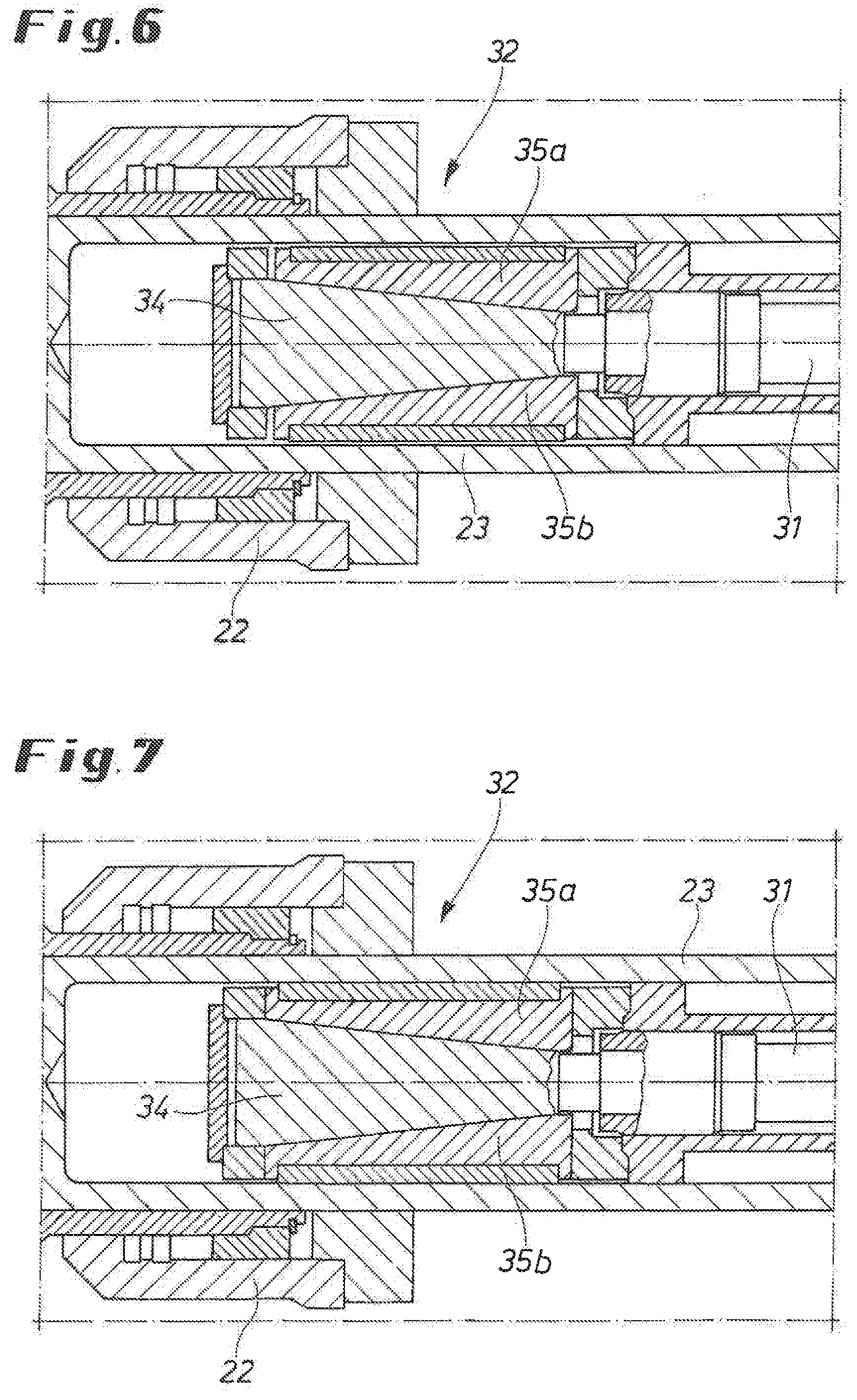
[0061] FIG. 6 shows as a detail of FIGS. 2 through 4, as a cross section, an embodiment of a clamping device in a non-activated position;
[0062] FIG. 7 shows the clamping device from FIG. 6 in an activated position;
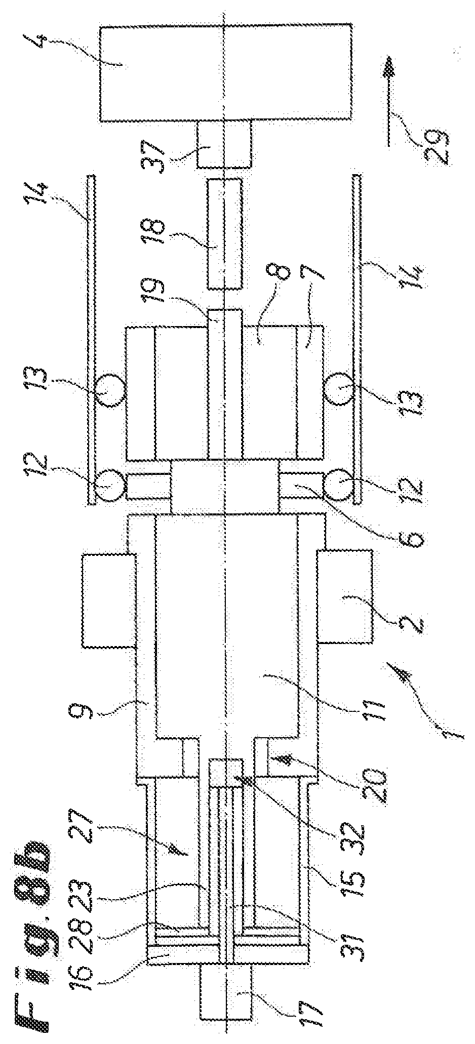
[0063] FIG. 8a, b show in a schematic side view (FIG. 8a) and top view (FIG. 8b) the press from FIG. 1 in its ingot loading position;
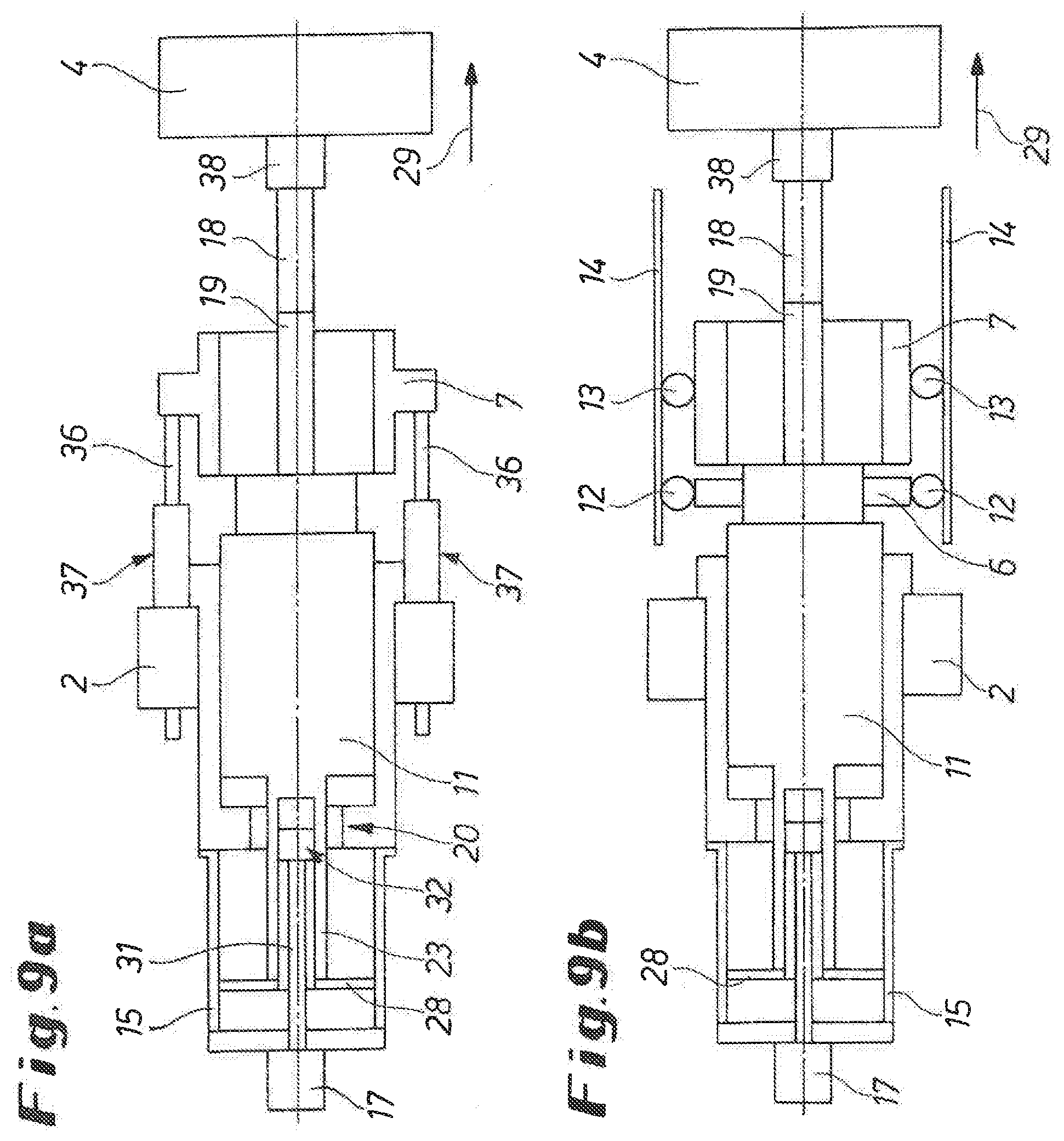
[0064] FIG. 9a, b show in a schematic side view (FIG. 9a) and top view (FIG. 9b) the press in its operating position for clamping a loaded ingot to be pressed;
[0065] FIG. 10a, b show in a schematic side view (FIG. 10a) and top view (FIG. 10b) the press in its operating position with an ingot container holder moved forward above the ingot to be pressed;
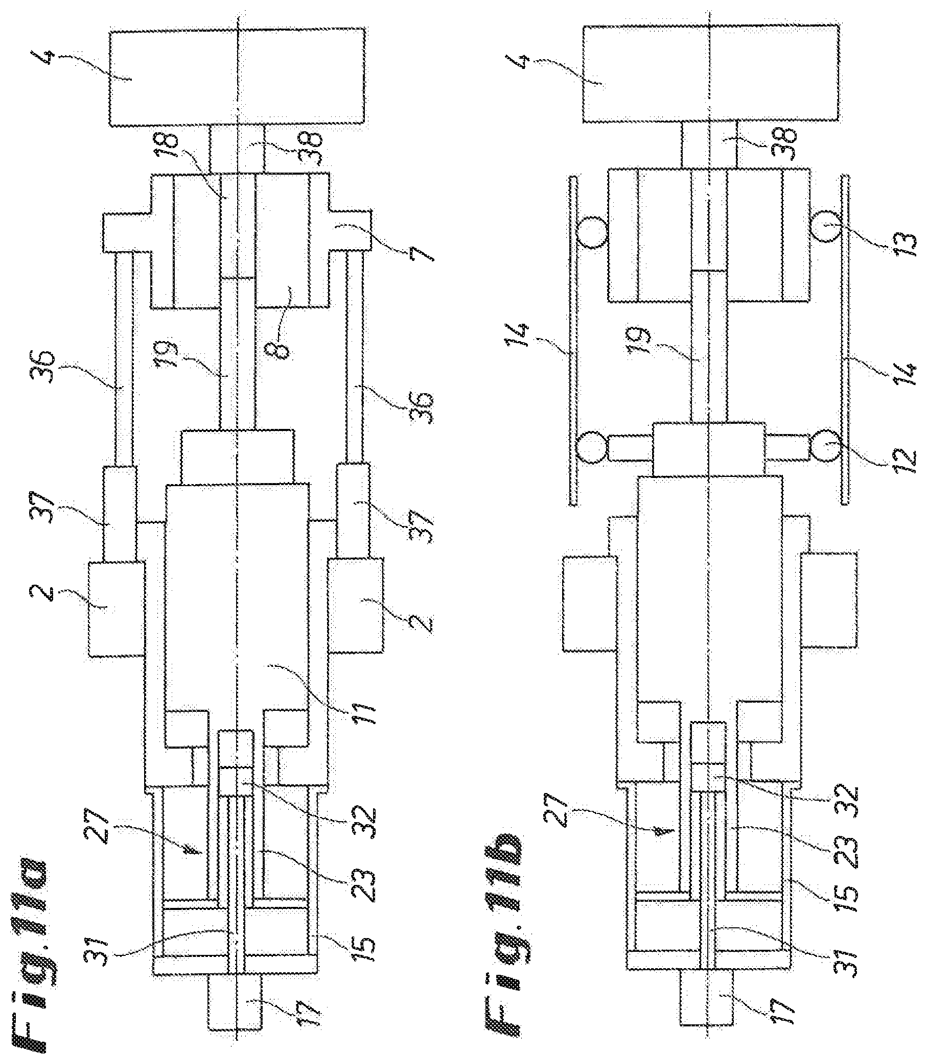
[0066] FIG. 11a, b show in a schematic side view (FIG. 11a) and top view (FIG. 11b) the press in its operating position for pre-compressing the ingot;
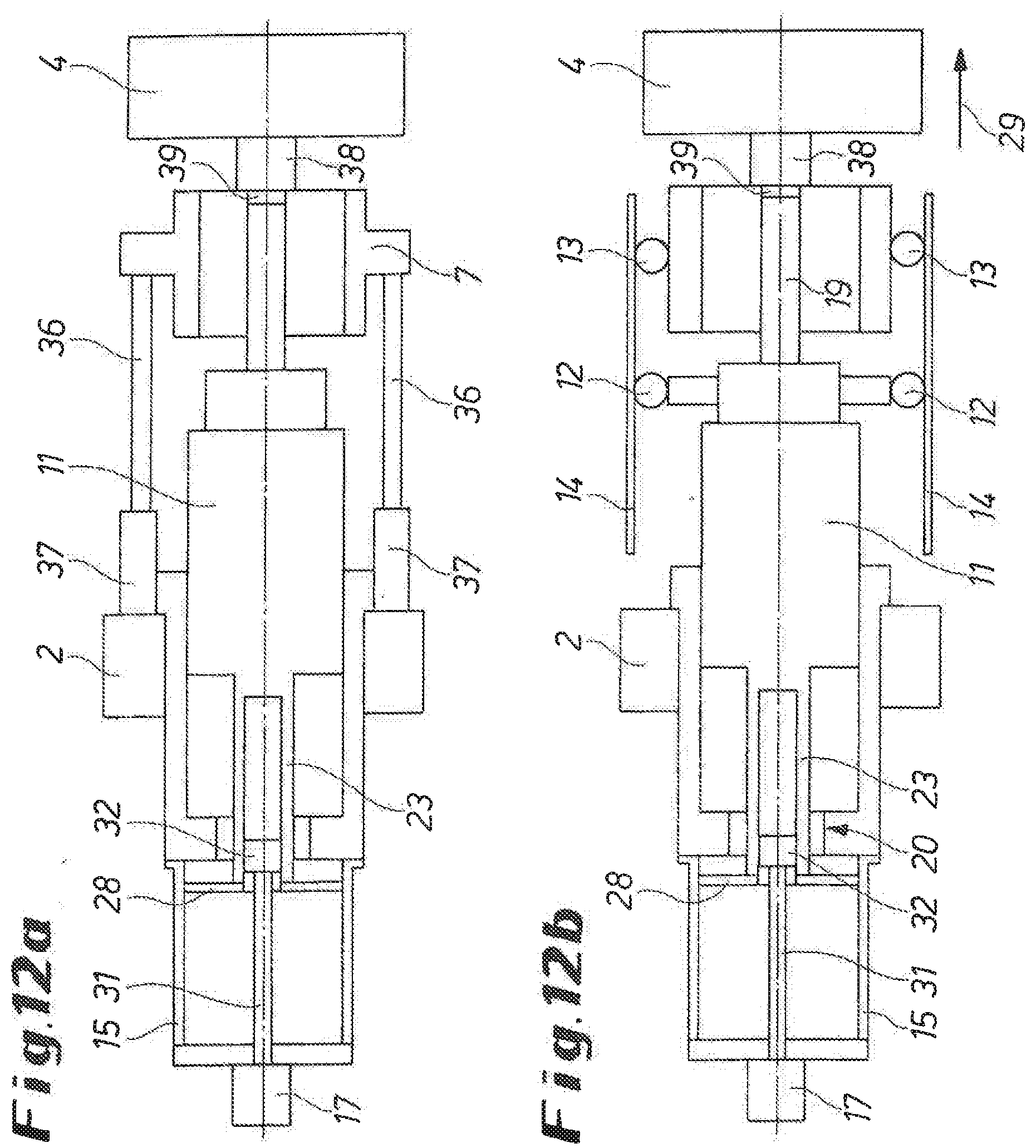
[0067] FIG. 12a, b show in a schematic side view (FIG. 12a) and top view (FIG. 12b) the operating position for pressing the ingot until a certain remaining extrusion butt length;
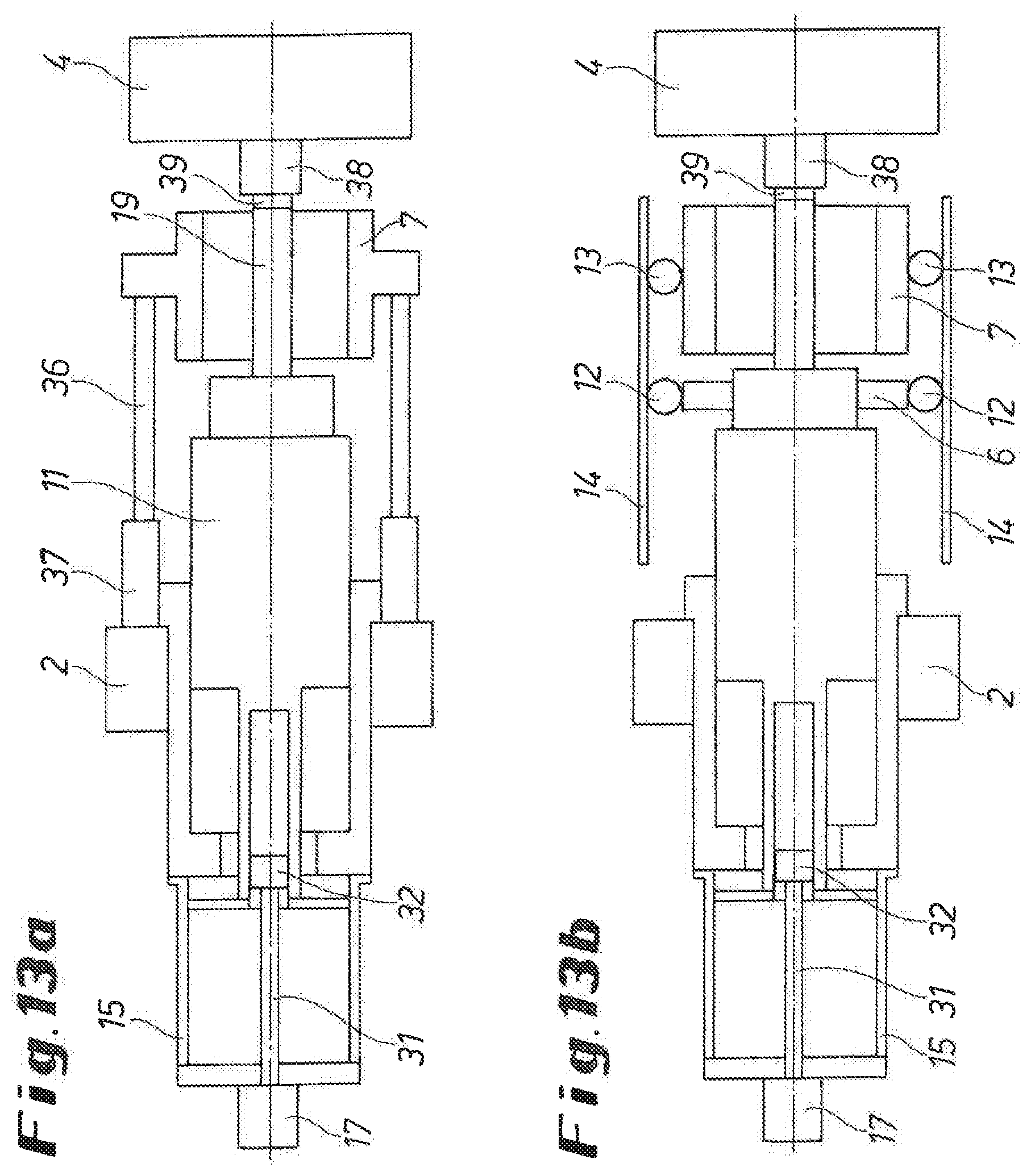
[0068] FIG. 13a, b show in a schematic side view (FIG. 13a) and top view (FIG. 13b) the operating position after the stripping of the remaining extrusion butt; and
[0069] FIG. 14a, b show in a schematic side view (FIG. 14a) and top view (FIG. 14b) the press having moved back into its ingot loading position.
DETAILED DESCRIPTION OF THE PREFERRED EMBODIMENT
[0070] Of a bar and tube extruding press or a metal extrusion press 1, FIG. 1 essentially shows a base frame. This consists of a cylinder bar 2 and a counter bar 4, not displayed here, which is braced to it by way of traction sipes 3 (cf. for instance, FIG. 8a). Further contributing to the frictional connection between these components are pressure columns 5, which envelop the traction sipes 3 between the cylinder bar 2 and the counter bar 4. The pressure columns 5 also serve as guide supports of a male die traverse 6 which is movable in the base frame, and of a movable ingot container holder 7. The ingot container holder 7, which holds an ingot container or recipient 8, is moved by way of electric motors 12 or 13, specifically of servo drives, like the male die traverse 6, which supports the advance end of a press piston 11 guided with hydrostatic bearings in its cylinder housing 9 in the counter bar 4 (cf. FIGS. 2 through 4). Such an electric motor 12 or 13 is provided on each longitudinal side of the ingot container holder 7 and the male die traverse 6. For the transmission or initiation of the movement, pinions of the electric motors 12 or 13 comb with toothed racks 14. Screwed onto the rear end of the cylinder housing 9 of the cylinder bar 2 is a compensation tank 15, and screwed onto the rear wall 16 of the compensation tank 15 is a cylinder unit 17. In order to upset and press an ingot 18 loaded into the ingot container 8, the press piston 11 has an extrusion die 19.
[0071] As shown in FIGS. 2 through 4, integrated into the cylinder housing 9 of the main or press cylinder is embodied a central filler valve 20, which consists of a large-scale valve cover 21 and a cylindrical ring 22 for operating the filler valve. In the exemplary embodiment, the tiller valve 20, which is shown more closely in FIG. 5, is positioned on an outer tube 23 connected to the rearward end of the press piston 11, interposed by a collar-shaped displacement sleeve 24, on which the cylindrical ring 22 is positioned as well. When applying hydraulic oil to the rearward end of the cylinder piston 25 of the cylindrical ring 22 in FIG. 5, the displacement sleeve 24, and therefore the filler valve cover 21, is moved out of its closing position, indicated by solid lines, and into the opening position, indicated by dashed lines, in which the filler valve cover 21 enters into a contour adjusted [sic] recess 26 of the press piston 11. In the opening position, a large and free flow cross-section or ring area is available, through which the hydraulic oil can flow from the compensation tank 15 to the pressure chamber of the cylinder housing 9 behind the press piston 11--and vice versa--without much resistance. In order to draw back the filler valve cover 21 into the closing position, the cylindrical ring 22 is switched over, so that hydraulic oil is brought before the cylinder piston 25 via the pressure oil lines, upon which the displacement sleeve 24 with the filler valve cover 21 is withdrawn correspondingly.
[0072] In this case, the outer tube 23 carrying the cylindrical ring 22 with the filler valve cover 21 is part of a rod assembly 27, which reaches into the compensation tank 15 and which features a slide plate 28 at that end, which, when the press piston 11 is charged, moves the hydraulic oil via the open filler valve cover 28, of which FIGS. 2 and 3 show the opening position, in the direction of the pressure according to arrow 29 into the pressure chamber behind the press piston 11, or when the filler valve cover 21 is closed for pressurizing as shown in FIG. 4, into a tank provided adjacent to the press, as shown by the downward arrow. The rod assembly 27 comprises a pressure bar 31 reaching into the outer tube 23, which is in an operative connection with the cylinder unit 17 which is flange-mounted onto the rearward end or onto the rear wall 16 of the compensation tank 15. The free end of the pressure bar 31 features a clamping device 32, via which the pressure bar 31 can be pressed from the inside against the outer tube 23 to [form] a rigid motion unit with it, when necessary, as in the mode of operation of the bar extruding press 1 for ingot upsetting shown in FIG. 3. The clamping device 32 is activated by the combined cylinder unit 17 due to the corresponding charge of its first coolant path 33.
[0073] In an embodiment of the clamping device 32 shown in FIGS. 6 and 7, it features a central spline 34 screwed onto the pressure bar 31, and its associated complementary keys 35a, 35b. When the clamping device 32 is not activated (cf. FIG. 6), the central spline 34 in the drawing left is moved out forward. When the clamping device 32 is then activated via the cylinder unit 17 (cf. FIG. 7), the spline 34 is pulled by the cylinder unit 17 to the right in the drawing, such that the complementary keys 35a, 35b press against the inner walls of the outer tube 23.
[0074] The combined electromotive and hydraulic operation of the bar and tube extruding press 1 will be described in further detail below with reference to FIGS. 8a, 8b through 14a, 14b. FIGS. 8a, and 8b show the ingot loading position, in which the ingot 18 to be pressed is brought into the center of the bar and tube extruding press 1 with a typical ingot loading device. As can be more clearly seen there, the bar and tube extruding press 1, apart from the previously described components, also comprises tow rods 36 on each side of ingot container holder 7, preferably on each side at the top and at the bottom, of which the free ends are guided through the cylinder bar 2 with freedom of movement (cf. also FIG. 1). The tow rods 36 are assigned to combined cylindrical ring and clamping units 37 that are attached the cylinder bar 2, in the ingot loading position, all moving parts are in the starting position, away from the counter bar 4.
[0075] The ingot container holder 7 and the male die traverse 6 with the press piston 11 and the extrusion die 19 are moved forward in the pressure direction 29 with an opened filler valve 20 (cf. FIG. 2) by means of the electric motors 12, 13 to the clamps shown in FIGS. 9a and 9b of the loaded ingot 18 between the extrusion die 19 and the tool or tool set 38 of the counter bar 4, with a first quantity of hydraulic oil being moved out of the compensation tank 15 into the pressure chamber behind the press piston 11. The ingot 18, which is now clamped, is moved into the ingot container 8 by moving forward the ingot container holder 7 by means of the electric motors 13, as shown in FIGS. 10a, 10b, with the tow rods 36 pulled along when the cylindrical rings and clamping units 37 are not activated, In order to seal the ingot container 8 against the tool set 37 [sic], the cylindrical rings and clamping units 37 are now activated, and the ingot container holder 7 or the ingot container 8 are moved by it against the tool 37.
[0076] FIGS. 11a, 11b show the resulting pressing or pre-compressing of the ingot 18, With the electric motors 12, 13 switched off, the combined cylinder unit 17 is loaded and the clamping device 32 is activated, so that the pressure bar 31 is pressed against the outer tube 23. Subsequently, the cylinder unit 17 transfers the pressure force onto the press piston 11 via the rigid rod assembly 27, consisting of the pressure bar 31 and the outer tube 23. A second partial quantity of hydraulic oil is moved out into the pressure chamber behind the press piston 11, as the filler valve is open in this pressure position as well (cf. FIG. 3). The subsequent pressing of the ingot to a remaining extrusion butt 39 is shown in FIGS. 12a and 12b. The clamping device 32 is deactivated for pressing, and the filler valve cover 21 of the integrated filler valve 20 is withdrawn into its closing position shown in FIG. 4 by means of the cylindrical ring 22, sealing the cylinder housing 9. The pressure force is applied through the feeding of hydraulic oil from the tank 30 into the pressure chamber behind the press piston 11, as indicated by the upward arrow show in FIG. 4. Since the filler valve 20 is closed and the clamping device 32 is deactivated, a third quantity of hydraulic oil is moved out of the compensation tank 15 with the press piston 11, which is moving from the filler valve cover 28 of the outer tube 23 in the pressure direction 29. This this quantity of hydraulic oil flows into the tank 30 (cf. FIG. 4).
[0077] In order to expose the extrusion butt 39 so that it can be sheared off before the ingot container 8, the combined cylindrical rings and clamping units 37 are switched over. The ingot container holder 7 is withdrawn via the clamped tow rods 36 by the length of the extrusion butt 39. This operating position after the stripping of the remaining extrusion butt 39 is shown in FIGS. 13a and 13b.
[0078] For the preparation of a new loading and pressing process, the ingot container holder 7 and the male die traverse 6 are moved back by the electric motors 12 and 13 as shown in FIGS. 14a, 14b, with the filler valve 20 being open to allow the hydraulic oil to flow out of the pressure chamber behind the press piston into the compensation tank 15, and with the clamping device 32 deactivated, and the cylindrical rings and clamping units 37 deactivated as well, whereupon the bar and tube extruding press 1 is ready for a new operating cycle.
* * * * *
D00001
D00002
D00003
D00004
D00005
D00006
D00007
D00008
D00009
D00010
D00011
D00012
D00013
D00014

XML
uspto.report is an independent third-party trademark research tool that is not affiliated, endorsed, or sponsored by the United States Patent and Trademark Office (USPTO) or any other governmental organization. The information provided by uspto.report is based on publicly available data at the time of writing and is intended for informational purposes only.
While we strive to provide accurate and up-to-date information, we do not guarantee the accuracy, completeness, reliability, or suitability of the information displayed on this site. The use of this site is at your own risk. Any reliance you place on such information is therefore strictly at your own risk.
All official trademark data, including owner information, should be verified by visiting the official USPTO website at www.uspto.gov. This site is not intended to replace professional legal advice and should not be used as a substitute for consulting with a legal professional who is knowledgeable about trademark law.