Implant Delivery Devices, Systems, And Methods
Kuzma; Janusz ; et al.
U.S. patent application number 16/595841 was filed with the patent office on 2020-02-06 for implant delivery devices, systems, and methods. The applicant listed for this patent is Oculeve, Inc.. Invention is credited to Douglas Michael Ackermann, Janusz Kuzma, Christopher William Stivers.
| Application Number | 20200038238 16/595841 |
| Document ID | / |
| Family ID | 51531281 |
| Filed Date | 2020-02-06 |


View All Diagrams
| United States Patent Application | 20200038238 |
| Kind Code | A1 |
| Kuzma; Janusz ; et al. | February 6, 2020 |
IMPLANT DELIVERY DEVICES, SYSTEMS, AND METHODS
Abstract
Described here are systems, devices, and methods for delivering an implant to the orbit. In some instances, the systems may comprise a delivery device having a tongue member and a handle. The delivery device may further include an ejector configured to deliver an implant from the tongue member. The delivery device may also include a piercing member configured to create an opening in tissue. The systems may further comprise a piercing member for creating an opening in tissue. In some instances, the piercing member may have a first blade member rotatably connected to a second blade member.
| Inventors: | Kuzma; Janusz; (Bayview, AU) ; Ackermann; Douglas Michael; (Reno, NV) ; Stivers; Christopher William; (San Francisco, CA) | ||||||||||
| Applicant: |
|
||||||||||
|---|---|---|---|---|---|---|---|---|---|---|---|
| Family ID: | 51531281 | ||||||||||
| Appl. No.: | 16/595841 | ||||||||||
| Filed: | October 8, 2019 |
Related U.S. Patent Documents
| Application Number | Filing Date | Patent Number | ||
|---|---|---|---|---|
| 15649364 | Jul 13, 2017 | |||
| 16595841 | ||||
| 14207072 | Mar 12, 2014 | 9717627 | ||
| 15649364 | ||||
| 61943921 | Feb 24, 2014 | |||
| 61778230 | Mar 12, 2013 | |||
| Current U.S. Class: | 1/1 |
| Current CPC Class: | A61F 9/0017 20130101; A61F 2/141 20130101; A61F 2/14 20130101; A61M 31/007 20130101; A61F 2/1662 20130101; A61M 2210/0612 20130101; A61F 9/007 20130101; A61F 2/148 20130101 |
| International Class: | A61F 9/007 20060101 A61F009/007; A61F 9/00 20060101 A61F009/00 |
Claims
1-31. (canceled)
32. A method for delivering an implant to an orbit, comprising: piercing, by a piercing member of a delivery device, the conjunctiva of the orbit to form an opening therein; advancing a tongue member of the delivery device through the opening to form a pocket beyond the conjunctiva; and delivering, from the tongue member, the implant into the pocket.
33. The method of claim 32, wherein the piercing member comprises a piercing tip and the tongue member comprises a tongue member tip.
34. The method of claim 33, wherein the piercing further comprises: retracting a control slider of the delivery device, thereby causing the piercing member to move between a retracted configuration in which the piercing tip does not extend beyond the tongue member tip and a piercing configuration in which the piercing tip extends beyond the tongue member tip.
35. The method of claim 33, wherein the method further comprises: moving the piercing member between a piercing configuration in which the piercing tip extends beyond the tongue member tip and a retracted configuration in which the piercing tip does not extend beyond the tongue member tip.
36. The method of claim 33, wherein the advancing comprises: advancing the tongue member with the piercing member in a retracted configuration in which the piercing tip does not extend beyond the tip of the tongue member.
37. The method of claim 32, wherein the delivery device further comprises: a handle; a control slider; and a pusher slidably attached to the tongue member.
38. The method of claim 37, wherein the delivering further comprises: advancing the control slider relative to the handle to thereby advance the pusher relative to the tongue member and deliver the implant into the pocket.
39. The method of claim 38, further comprising: withdrawing the control slider relative to the handle to thereby withdraw the pusher relative to the tongue member.
40. The method of claim 32, further comprising: dilating the opening.
41. The method of claim 40, wherein dilating the opening comprises dilating the opening with the delivery device.
42. A method for delivering an implant to the conjunctiva of a patient, comprising: forming, by a piercing member of a delivery device, an opening in the conjunctiva of the patient; forming, by a tongue member of the delivery device, a pocket beyond the conjunctiva; and delivering, from the tongue member of the delivery device, the implant into the pocket.
43. The method of claim 42, wherein the piercing member comprises a piercing tip and the tongue member comprises a tongue member tip.
44. The method of claim 43, wherein the method further comprises: retracting a control slider of the delivery device, thereby causing the piercing member to move between a retracted configuration in which the piercing tip does not extend beyond the tongue member tip and a piercing configuration in which the piercing tip extends beyond the tongue member tip.
45. The method of claim 43, wherein the method further comprises: moving the piercing member between a piercing configuration in which the piercing tip extends beyond the tongue member tip and a retracted configuration in which the piercing tip does not extend beyond the tongue member tip.
46. The method of claim 43, wherein the delivering comprises: advancing the tongue member with the piercing member in a retracted configuration in which the piercing tip does not extend beyond the tip of the tongue member.
47. The method of claim 42, wherein the delivery device further comprises: a handle; a control slider; and a pusher slidably attached to the tongue member.
48. The method of claim 47, wherein the delivering further comprises: advancing the control slider relative to the handle to thereby advance the pusher relative to the tongue member and deliver the implant into the pocket.
49. The method of claim 48, further comprising: withdrawing the control slider relative to the handle to thereby withdraw the pusher relative to the tongue member.
50. The method of claim 42, further comprising dilating the opening.
51. The method of claim 50, wherein dilating the opening comprises dilating the opening with the delivery device.
Description
CROSS-REFERENCE TO RELATED APPLICATIONS
[0001] This application is a divisional of U.S. patent application Ser. No. 15/649,364, filed Jul. 13, 2017, and titled "IMPLANT DELIVERY DEVICES, SYSTEMS, AND METHODS," which is a divisional of U.S. patent application Ser. No. 14/207,072, filed Mar. 12, 2014, issued as U.S. Pat. No. 9,717,627, and titled "IMPLANT DELIVERY DEVICES, SYSTEMS, AND METHODS," which claims priority to U.S. Provisional Patent Application Ser. No. 61/778,230, filed Mar. 12, 2013 and titled "IMPLANT DELIVERY DEVICES, SYSTEMS, AND METHODS" and to U.S. Provisional Patent Application Ser. No. 61/943,921, filed Feb. 24, 2014 and titled "IMPLANT DELIVERY DEVICES, SYSTEMS, AND METHODS," the contents of each of which are hereby incorporated in their entirety.
FIELD
[0002] The present invention relates generally to systems, devices, and methods for delivering an implant to a portion of the anatomy such as the orbit.
BACKGROUND
[0003] Treatment methods for ocular conditions such as dry eye may require delivery of an implant or other device to the orbit of a patient. The orbit is a cavity of the skull that houses the eyeball and its nerves, muscles, and other appendages. The presence of these anatomical structures within the orbit, which in some instances may be easily damaged, can provide a limited working space for delivery of implants. Accordingly, it may be desirable to provide one or more devices which may facilitate delivery of one or more implants to the orbit.
BRIEF SUMMARY
[0004] Described here are systems, devices, and methods for delivering an implant to the orbit. In some variations, the devices described here may comprise a handle and a tongue member extending from a distal portion of the handle. In some variations, the devices may further comprise an ejector. In some of these variations, the ejector may comprise a control slider slidably attached to the handle, a pusher slidably attached to the tongue member, and a linkage connecting the control slider and the pusher. In these variations, advancement of the control slider relative to the handle may advance the pusher relative to the tongue member, and withdrawal of the control slider relative to the handle may withdraw the pusher relative to the tongue member. In some of these variations, the tongue member may be curved, and in some variations may comprise a tapered tip. Additionally or alternatively, the tongue member may comprise one or more depth stops positioned along a length of the tongue member. In some of these variations, the one or more depth stops comprises one or more projections or protrusions. In others of these variations, the one or more depth stops comprises one or more notches. In still other variations, the one or more depth stops comprises one or more markers.
[0005] In some variations, the devices described here may comprise a piercing member having a piercing tip. In some variations, the piercing member may be moveable between a piercing configuration in which the piercing tip extends beyond a tip of the tongue member and a retracted configuration in which the piercing tip does not extend beyond a tip of the tongue member. In some variations, the piercing member may be biased toward the retracted configuration. Additionally or alternatively, in variations of the devices described here comprising a control slider, the control slider may be configured to move the piercing member from the retracted configuration to the piercing configuration. In some of these variations, control slider may be configured to move the piercing member from the retracted configuration to the piercing configuration during withdrawal of the control slider.
[0006] In some variations, the devices described here may further comprise a rocker, wherein the rocker is rotatably connected to the handle, wherein the device is configured such that rotation of the rocker in a first direction to a first position moves the piercing member to the piercing configuration, and wherein rotation of the rocker in a second direction opposite the first direction to a second position moves the piercing member to the retracted configuration. In some of these variations, the rocker may be biased toward the second position. In variations where the device comprises a control slider, the control slider may be configured to rotate the rocker in the first direction. In some of these variations, the control slider may comprise a button, wherein depression of the button rotates the rocker in the first direction. In some of these variations, the control slider may be slidable along the handle between a retracted position and an advanced position, and the handle may configured to allow depression of the button when the control slider is in the retracted position and to prevent depression of the button when the control slider is in the advanced position.
[0007] In some variations of the systems described here, the system may comprise an implant, and a delivery device comprising a handle, a tongue member extending from the handle, and an ejector. In these variations, the implant may be releasably and slidably connected to the tongue member, and the ejector may advance the implant relative to the tongue member to release the implant from the tongue member. In some of these variations, the system further comprises a piercing device, wherein the piercing device comprises a first blade member pivotally attached to a second blade member. In other variations, the delivery device may further comprises a piercing member moveable between a piercing configuration in which the piercing tip extends beyond a tip of the tongue member and a retracted configuration in which the piercing tip does not extend beyond a tip of the tongue member.
[0008] In other variations of the devices described here, the devices may comprise a first blade member and a second blade member pivotally connected to the first blade member, each comprising a tip, an inner edge, an outer edge, and a notch positioned along the outer edge. The device may further comprise a first grip connected to the first blade member and a second grip connected to the second blade member. Rotation of the first and second grip may rotate the first and second blade members between a first configuration in which the tip of the first blade member coincides with the tip of the second blade member to form a point, and a second configuration in which the tip of the first blade member is spaced apart from the tip of the second blade. In some of these variations, a distance between the notch of the first blade member and the notch of the second blade member in the first configuration is less than a distance between the notch of the first blade member and the notch of the second blade member in the second configuration. In some variations, the device may further comprise a spring member biasing the first grip away from the second grip. Additionally or alternatively, the device may further comprise a range-limiting element configured to limit the amount that the first grip may rotate away from the second grip. Additionally or alternatively, the device may further comprise a range-limiting element configured to limit the amount that the first grip may rotate toward the second grip.
[0009] Also described here are methods for delivering an implant into an orbit. In some variations, the methods may comprise piercing the conjunctiva to form an opening therein, advancing a tongue member of a delivery device through the opening to form a pocket between tissues beyond the opening, and delivering an implant from the tongue member into the pocket. In some variations, the method may further comprise dilating the opening. In some of these variations, piercing the conjunctiva and dilating the opening may comprise piercing the conjunctiva and dilating the opening with a piercing device. In others of these variations, piercing the conjunctiva and dilating the opening may comprise piercing the conjunctiva and dilating the opening with the delivery device. In some of these variations, the delivery device may comprise a piercing member moveable between a piercing configuration in which a piercing tip of the piercing member extends beyond a tip of the tongue member and a retracted configuration in which the piercing tip does not extend beyond a tip of the tongue member. In some of these variations, piercing the conjunctiva may comprise piercing the conjunctiva with the piercing tip of the piercing member. Additionally or alternatively, advancing the tongue member may comprise advancing the tongue member with the piercing member in the retracted configuration.
[0010] In other variations of the systems described here, the system may comprise a delivery device. The delivery device may comprise a cannula defining a channel extending between an inlet and an outlet, the cannula comprising a blade. The delivery device may further comprise a tongue slidably connected to the cannula and positioned to extend at least partially through the channel, and a plunger slidably connected to the cannula and positioned to extend at least partially through the channel. The cannula may comprise a top wall, wherein the top wall comprises a slot extending at least partially along the channel. In some of these variations, the plunger may be positioned between the tongue and the top wall. In some variations, the plunger comprises a plunger portion, a stopper portion, and a transition region connecting the stopper portion and the plunger portion. The plunger may be positioned such that the plunger portion of the plunger is positioned at least partially inside the channel, the stopper portion is positioned outside of the channel, and the transition region extends through the slot of the top wall. In some of these variations, a distal end of the stopper portion may extend distally of a distal end of the transition region to define a space between a distal portion of the stopper portion and the plunger portion. In some of these variations, the cannula may comprise a stop bar having an aperture therethrough, and the distal portion of the stopper portion may be sized to fit through the aperture of the stop bar. In some variations, the stop bar is perpendicular to a longitudinal axis of the cannula. In other variations, the stop bar may be positioned an angle clockwise of the longitudinal axis, wherein the angle is less than 90 degrees. In still other variations, the stop bar may be positioned an angle clockwise of the longitudinal axis, wherein the angle is greater than 90 degrees. In some variations where a top wall of the cannula comprises a slot, the slot may comprise a proximal segment, a distal segment, and an intermediate segment positioned between the proximal segment and the distal segment. In some of these variations, the intermediate segment may have a width greater than or equal to a width of the implant, and the distal segment may have a width less than the width of the implant.
[0011] In some variations, the tongue may be moveable between a retracted position in which a distal end of the tongue is positioned in the channel and an advanced position in which a distal end of the tongue is positioned distally of the outlet of the channel. In some of these variations, the tongue may comprise a handle, wherein the handle is sized to be prevented from entering the inlet, and wherein the handle of the tongue contacts the inlet when the tongue is in the advanced position. In some of these variations, the distal end of the tongue is positioned distal to a distal end of the blade when the tongue is in the advanced position. Additionally or alternatively, the plunger may comprise a handle, and the plunger and tongue may be positioned such that the handle of the tongue is prevented from being withdrawn proximally of the handle of the plunger.
[0012] In some variations, the plunger may be moveable between a retracted position in which a distal end of the plunger is positioned in the channel and an advanced position in which a distal end of the plunger is positioned distally of the outlet of the channel. In some of these variations, the delivery device further comprises an intermediate stop positioned to temporarily prevent advancement from the retracted position to the advanced position. In some of these variations, the intermediate stop may comprise a bumper plate moveable between a lowered position and a raised position, wherein the bumper plate prevents advancement of the plunger to the advanced position when the bumper plate is in the lowered position and wherein the bumper plate does not prevent advancement of the plunger to the advanced position when the bumper plate is in the raised position. In some of these variations, the delivery device comprises on or more springs connecting the bumper plate to the cannula. In some of these variations, the one or more springs bias the bumper plate toward the raised position. Additionally or alternatively, the bumper plate may comprise an extension positioned to extend into the channel through the slot of the top wall when the bumper plate is in the lowered position. In some variations, the delivery device may further comprise a release bracket, wherein the release bracket is positioned to releasably hold the bumper plate in the lowered position. In some variations, the system may comprise a biasing member connected to the cannula, wherein the biasing member has a first end connected to a bottom wall of the channel and a free end biased toward a top wall of the channel. In some variations, the system may further comprise an implant.
[0013] In some variations, the methods described here may comprise piercing tissue with a blade of a cannula of a delivery device to form a tissue opening, advancing a tongue through a channel of the cannula to advance a distal end of the tongue out of an outlet of the channel and through the tissue opening, and advancing a plunger through the channel of the cannula to advance the implant out of the outlet of the channel and through the tissue opening to deliver the implant to a pocket formed between tissue beyond the tissue opening. In some of these variations, the cannula may comprise a top wall, wherein the top wall comprises a slot extending at least partially along the channel. In some of these variations, advancing the plunger may comprise advancing the plunger between the tongue and the top wall. In some of these variations, the plunger may comprise a plunger portion, a stopper portion, and a transition region connecting the stopper portion and the plunger portion, and advancing the plunger may comprise advancing the plunger with the plunger portion of the plunger is positioned at least partially inside the channel, the stopper portion positioned outside of the channel, and the transition region extending through the slot of the top wall. In some of these variations, a distal end of the stopper portion may extend distally of a distal end of the transition region to define a space between a distal portion of the stopper portion and the plunger portion. In these variations, advancing the plunger may comprise advancing the plunger such that a distal end of the stopper portion as advanced distally of a distal end of the slot of the top wall. In some of these variations the cannula comprises a stop bar having an aperture therethrough, and advancing the plunger comprises advancing the distal portion of the stopper portion through the aperture of the stop bar.
[0014] In some variations where a top wall of a cannula comprises a slot, the slot comprises a proximal segment, a distal segment, and an intermediate segment positioned between the proximal segment and the distal segment. In some of these variations, the intermediate segment has a width greater than or equal to a width of the implant, and the method further comprises inserting the implant into the channel through the intermediate segment. In some variations, advancing the tongue comprises advancing the tongue from a retracted position in which the distal end of the tongue is positioned in the channel. In some of these variations, the tongue comprises a handle, wherein the handle is sized to be prevented from entering the inlet, and advancing the tongue comprises advancing the tongue until the handle of the tongue contacts the inlet. In some of these variations, the distal end of the tongue is positioned distal to a distal end of the blade when the handle of the tongue contacts the inlet. In some of these variations, the plunger comprises a handle, and the plunger and tongue are positioned such that the handle of the tongue is prevented from being withdrawn proximally of the handle of the plunger.
[0015] In some variations, advancing the plunger comprises advancing the plunger from a retracted position in which the distal end of the tongue is positioned in the channel. In some of these variations, the method may further comprise advancing the plunger to an intermediate position, wherein an intermediate stop is positioned to temporarily prevent further advancement of the plunger. In some of these variations, the intermediate stop comprises a bumper plate moveable, and the method further comprises raising the bumper plate from a lowered position to a raised position to allow further advancement of the plunger. In some of these variations, the delivery device comprises on or more springs connecting the bumper plate to the cannula. The one or more springs may bias the bumper plate toward the raised position. Additionally or alternatively, the bumper plate comprises an extension positioned to extend into the channel through the slot of the top wall when the bumper plate is in the lowered position. Additionally or alternatively, the delivery device further comprises a release bracket. The release bracket may be positioned to releasably hold the bumper plate in the lowered position, and raising the bumper plate from a lowered position to a raised position may comprise deflecting the release bracket.
BRIEF DESCRIPTION OF THE DRAWINGS
[0016] FIG. 1A depicts a perspective view of an illustrative variation of one of the delivery devices described here. FIG. 1B shows a side view of a distal portion of the delivery device of FIG. 1A. FIGS. 1C-1E show perspective views of a distal portion of the delivery device of FIG. 1A. FIG. 1F shows a top view of a distal portion of the delivery device of FIG. 1A. FIGS. 1G and 1H show cross-sectional side views a distal portion of the delivery device of FIG. 1A.
[0017] FIG. 2A depicts a perspective view of an illustrative variation of one of the delivery devices described here. FIGS. 2B and 2C depict side and perspective views, respectively, of the delivery device of FIG. 2A. FIGS. 2D and 2E show cross-sectional side views a distal portion of the delivery device of FIG. 2A.
[0018] FIGS. 3A and 3B depict a variation of a piercing device suitable for use with the systems described here.
[0019] FIGS. 4A-4D depict an illustration variation of one of the methods described here.
[0020] FIG. 5A depicts a perspective view of a lacrimal apparatus. FIGS. 5B and 5C depict front views of the anatomy of the skull.
[0021] FIG. 6A depicts a perspective view of an illustrative variation of one of the delivery devices described here. FIG. 6B shows a side view of a distal portion of the delivery device of FIG. 6A.
[0022] FIG. 7 depicts a perspective view of a variation of a delivery system as described here.
[0023] FIGS. 8A-8C depict perspective, top, and side views, respectively, of a variation of a cannula suitable for use with the delivery system of FIG. 7.
[0024] FIGS. 9 and 10 show side views of variations of plungers suitable for use with the delivery system of FIG. 7.
[0025] FIGS. 11A-11I depict an illustrative method by which the delivery system of FIG. 7 may be used to deliver an implant.
[0026] FIGS. 12A-12D depict perspective, side, top, and front views, respectively of a variation of a delivery device as described here. FIGS. 12E and 12F depict perspective views and FIGS. 12G and 12H depict side views of the delivery device of FIGS. 12A-12D. FIG. 12I depicts a top view of the cannula of the delivery device of FIGS. 12A-12H.
[0027] FIGS. 13A and 13B depict rear perspective views and FIGS. 13C and 13D depict front perspective views of a variation the cannula of the delivery device of FIGS. 12A-12I having a bumper plate.
DETAILED DESCRIPTION
[0028] Described here are systems, devices, and methods for delivery of an implant into the orbit. Generally, the systems and devices may be configured to deliver one or more implants into tissue within the orbit (e.g., between the eyeball and the bones forming the orbit). Generally, the systems and devices described here may be used to form an opening in a tissue, such as the conjunctiva, to separate tissue beyond the opening to form a pocket in the tissue, and to deliver an implant into the pocket. The systems described here may include one or more devices configured to perform these steps. In some instances, the systems include a single device that performs all of the steps. In other instances, the system may include multiple devices which collectively perform these steps. The devices described here may be sterilizable (and in some instances, resterilizable), and may or may not be disposable (or partially disposable). Examples of these devices, systems, and methods will be described in more detail below.
[0029] The systems, devices, and methods described here may be used to deliver any suitable implant or implants. In some variations, the implant may include a stimulation device or one or more components thereof. The stimulation device may be configured to provide stimulation therapy to one or more target tissues. In some instances, the stimulation device may be configured to excite or activate an anatomic structure (e.g., the lacrimal gland). Additionally or alternatively, the stimulation device may be configured to inhibit activity of anatomic structure (e.g., one or more pain-transmitting nerves). The systems, devices, and methods may be configured to deliver the entire stimulation device, or may be configured to deliver one or more components thereof (e.g., one or more electrode-bearing leads). In some variations, the stimulation device may be any device such as described in U.S. patent application Ser. No. 13/441,806, titled "STIMULATION DEVICES AND METHODS" and filed on Apr. 6, 2012, which is hereby incorporated by reference in its entirety.
[0030] Additionally or alternatively, the implant may include one or more drug-releasing devices or substances. In variations where the implant includes a stimulation device, the stimulation device may be configured to elute or otherwise release one or more drugs. In other variations, the implant may include an implantable pump which is configured to dispense one or more drug-containing substances. In yet other variations, the implant may include one or more drug-releasing depots (e.g., a solid or gel-like depot, which may or may not be formed from a polymer) and/or one or more drug-releasing liquids or gases. Additionally or alternatively the implant may comprise an orthopedic support (e.g., a wedge, shim, or the like) which is configured to provide structural support to surrounding tissue. In still other variations, the implant may comprise one or more mesh implants, retinal detachment treatment methods, or the like.
[0031] When the systems, devices, and methods described here are used to deliver an implant or implants to the orbit, the implants or implants may be delivered to any suitable portion of the orbit, such as, for example, the upper orbit, the lower orbit, the nasal orbit, the temporal orbit, the anterior orbit, and/or the posterior orbit. In some variations, the systems and devices described here may be used to deliver an implant to the lacrimal fossa. In some of these variations, the implant may be delivered in, on, or near the lacrimal gland. For example, in some instances the systems and methods described here may be used to position and deliver an implant in the lacrimal fossa between the lacrimal gland and the fontal bone of the orbit.
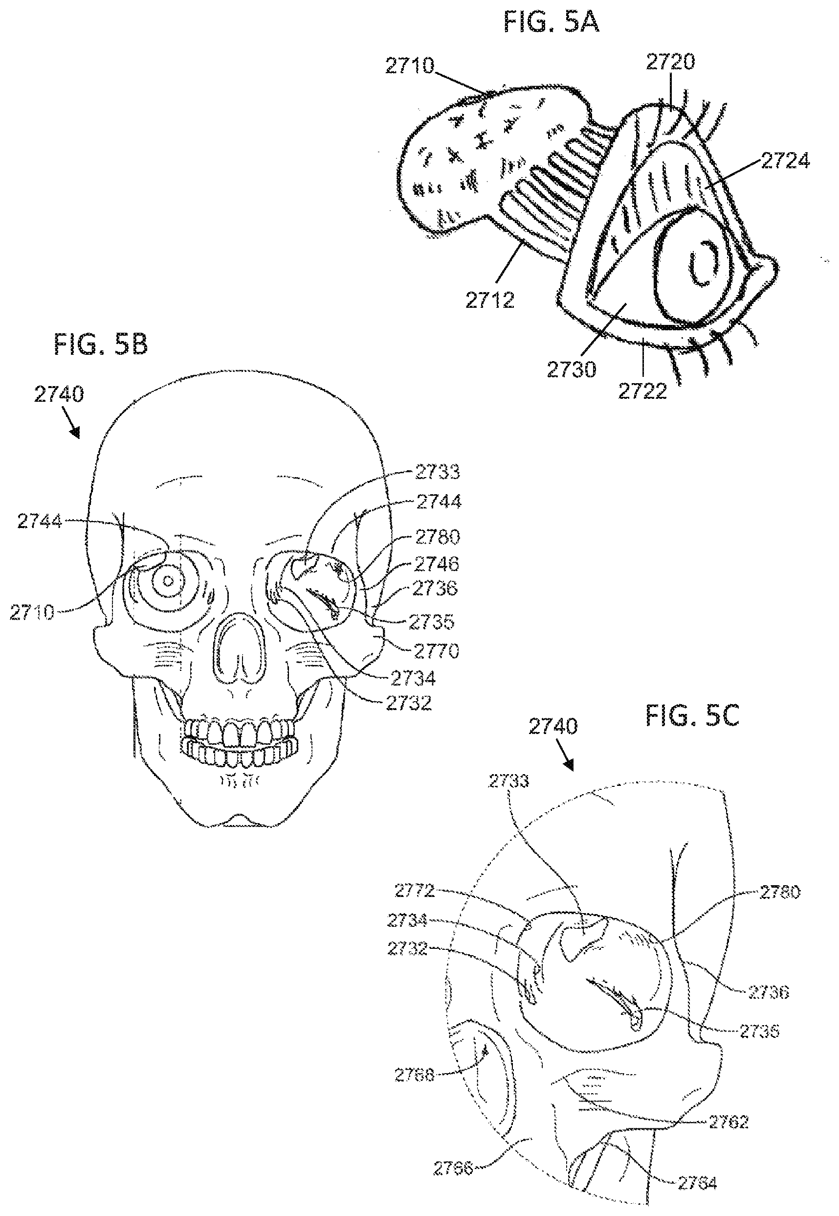
[0032] For the purposes of illustration, FIGS. 5A-5C depict various views of the anatomy of the head of a patient. FIG. 5A illustrates the lacrimal (or lachrymal) apparatus, the physiological system that contains the structures of the orbit for tear production and drainage. Shown there is an eye (2730) having an upper lid (2720) and a lower lid (2722). The upper lid (2722) is shown in FIG. 5A as being raised to reveal the conjunctiva (2724), which may line the inside of the eyelids and cover the sclera of the eye (2730). The lacrimal apparatus may include a lacrimal gland (2710) and ducts (2712). The lacrimal gland (2710) may secrete lacrimal fluid (i.e., tears) which may flow through the ducts (2712) into the space between the eye (2730) and the upper (2720) and lower (2722) lids. The lacrimal gland (2710) may be innervated by several nerves. These nerves may include the rami lacrimales, the lacrimal nerve, perivascular nerves of lacrimal artery, and sympathetic nerves fibers and neurites which innervate the lacrimal gland and its associated vasculature. When the eye (2730) blinks, the lacrimal fluid may be spread across the surface of the eye (2730). The lacrimal fluid (2714) may collect in the lacrimal lake (not shown), and may be drawn into the puncta (not shown) by capillary action. The lacrimal fluid may flow through lacrimal canaliculi (not shown) at the inner corner of the upper (2720) and lower (2722) lids to enter lacrimal ducts (not shown) and drain through to the nasolacrimal duct (not shown). The lacrimal fluid may drain from the nasolacrimal duct into the nasal cavity of the patient.
[0033] FIG. 5B shows a front view of the skull, and emphasizes the anatomy of the orbit with respect to the bones of the skull (2740). FIG. 5C shows an enlarged view of the left orbit of the skull (2740). As shown there, the exterior to the orbit includes the posterior lacrimal crest (2734), the supraorbital process (2744), the frontal process (2746), the sphenoid bone (2736), and the zygomatic bone (2770). The interior of the left orbit includes the superior orbital fissure (2733), inferior orbital fissure (2735), the fossa for the lacrimal gland (2780) and the fossa for the lacrimal sac (2732). The structures that enter the orbit through the superior orbital fissure may include the cranial nerves (CN) III, IV, and VI, lacrimal nerve, frontal nerve, nasociliary nerve, orbital branch of middle meningeal artery, recurrent branch of lacrimal artery, superior orbital vein, and the superior ophthalmic vein. The structures that enter the orbit through the inferior orbital fissure may include the infraorbital nerve, zygomatic nerve, parasympathetics to the lacrimal gland, infraorbital artery, infraorbital vein, and inferior ophthalmic vein branch to pterygoid plexus. Some of the bony structures and regions shown in FIG. 5C include, but are not limited to, the infraorbital foramen (2762), the maxillary axis (2764), the nasal-maxillary area (2766), the nasal cavity (2768), and the inferior medial aspect of the supraorbital process (2772).
[0034] Generally, the methods described here comprise piercing a first tissue to form an opening therein, forming a pocket in tissue beyond the opening, delivering an implant into that pocket, and, in some variations, closing the opening in the first tissue. In some variations, the methods further comprise dilating the opening formed in the first tissue. For example, in some variations, the methods comprise piercing the conjunctiva to form an opening therein, separating tissue beyond the conjunctiva to form a pocket in the tissue, and delivering an implant into the pocket. In some of these variations, the pocket is formed between the lacrimal gland and the frontal process of the orbit. In some variations, the methods further comprise closing the opening in the conjunctiva.
[0035] When the methods described here comprise piercing the conjunctiva to form an opening therein, it may be necessary to either move or pierce the eyelid covering the conjunctiva. Accordingly, in some variations, the method may comprise retracting an eyelid. In these variations, the eyelid may be held in a retracted position (e.g., using one or more tools, a finger, or the like). In other variations, the methods may comprise piercing both the eyelid and the conjunctiva. In variations that include piercing the eyelid, the method may further comprise tensioning the eyelid, which may facilitate piercing of the eyelid. Additionally or alternatively, the method may further comprise raising a user's brow to pull a portion of the eyelid into the eyelid crease under the frontal process.
[0036] When piercing the conjunctiva, it may be desirable to create tension in the conjunctiva before and/or during piercing of the conjunctiva. For example, the patient may be directed to look away from the intended piercing location, which may act to tension the conjunctiva. Additionally or alternatively, retracting the eyelid may act to at least partially tension the conjunctiva (and may also move structures such as the cornea away from the insertion point). In some variations, once the conjunctiva has been pierced to form an opening therein, the opening in the conjunctiva may be dilated, such as will be described in more detail below. Dilating of the opening in the conjunctiva may facilitate introduction of a portion of delivery device through the opening.
[0037] Following formation (and dilation, when the methods include a dilation step) of the opening, a portion of a delivery device may be advanced through the opening in the conjunctiva to form a pocket between tissue beyond the conjunctiva. For example, in some variations, this may include forming a pocket between the lacrimal gland and the frontal process of the orbit. In some of these variations, this may further include forming a pocket between the periosteum and the lacrimal gland. In others of these variations, this may further include forming a pocket between the periosteum and the bone of the orbit. In other variations, this may include forming a pocket between the lacrimal gland and the tarsus of the eyelids. The pocket is preferably formed using a blunt portion of the device, which may reduce the likelihood of inadvertently damaging tissue such as the eye or the lacrimal gland.
[0038] An implant (or plurality of implants) may be delivered into the pocket formed between tissues beyond the conjunctiva. In some instances, the implant may be delivered simultaneously with the formation of the pocket. In other variations, the implant may be delivered after formation of the pocket. In some instances, the methods may also comprise removing any delivery devices that have been advanced into the conjunctiva or the tissues beyond the conjunctiva. Removal of the one or more delivery devices may occur simultaneously with delivery of the implant, or may occur after the implant has been delivered. Following removal of the one or more delivery devices, the opening in the conjunctiva may be closed. The opening may be closed in any suitable manner. In some variations, the opening may be closed using one or more sutures, one or more adhesives, electrocautery techniques, one or more staples, combinations thereof, and the like. In some instances, the methods may not comprise a separate closing step, as the opening of the conjunctiva may naturally contract sufficiently to at least partially close the opening.
[0039] The methods described here may be performed by a system including one or more delivery devices. In some variations, the system may include a single device which may be used to pierce the conjunctiva to form an opening (and to dilate the opening in variations that comprise a dilating step), create the pocket between tissue beyond the conjunctiva, and deliver the implant. In other variations, a first device may be used to pierce the conjunctiva to form an opening (and to dilate the opening in variations that comprise a dilating step), while a second device may be inserted into the opening to form the pocket between tissues beyond the conjunctiva. The second device may be further used to deliver the implant. In yet other variations, a first device may be used to pierce the conjunctiva to form an opening in the conjunctiva (and to dilate the opening in variations that comprise a dilating step), a second device may be inserted into the opening to form the pocket between tissues beyond the conjunctiva, and a third device may be advanced into the pocket to deliver the implant. Any suitable delivery devices as described here may be used to perform one or more of these steps, and several illustrative devices will be described in more detail below.
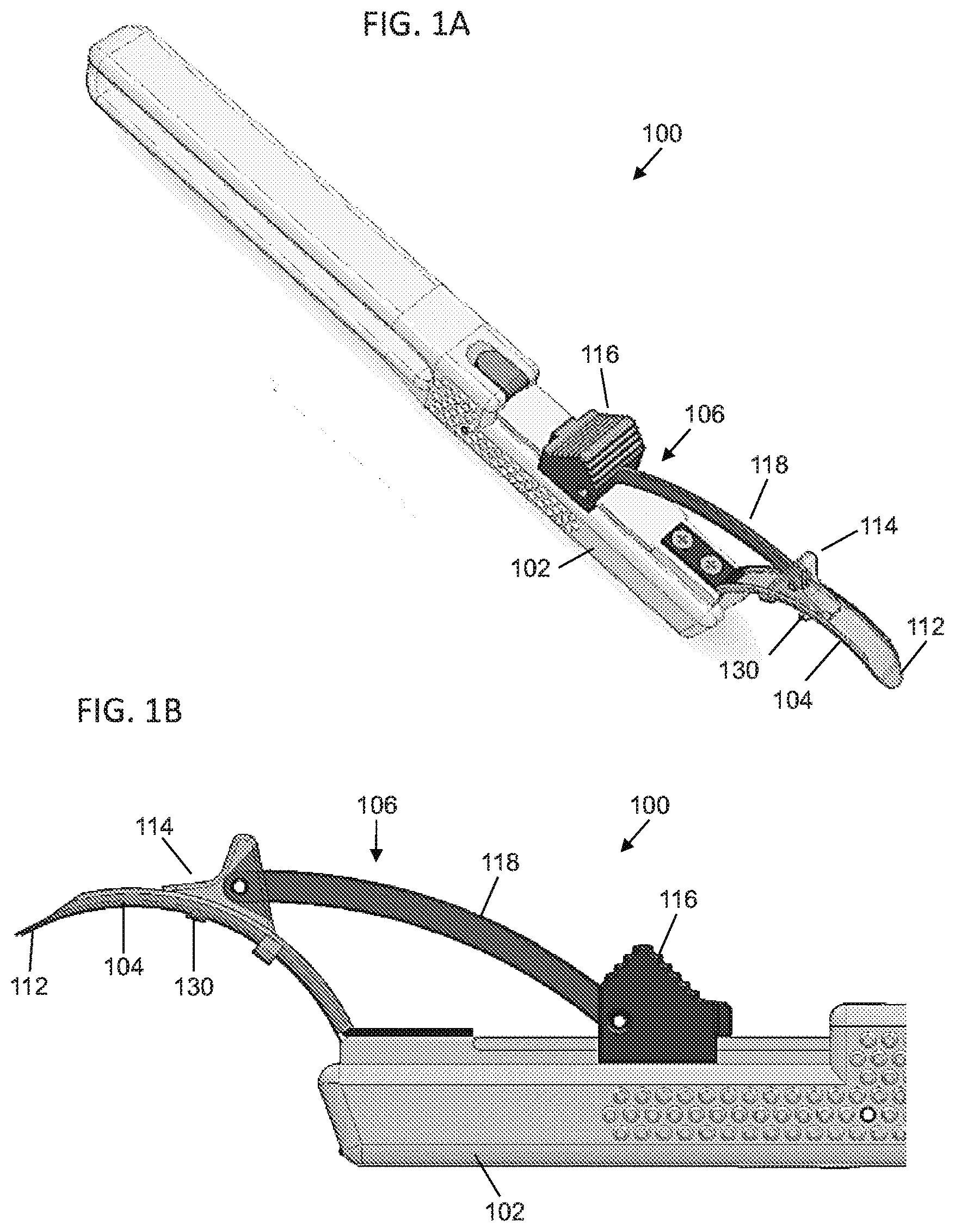
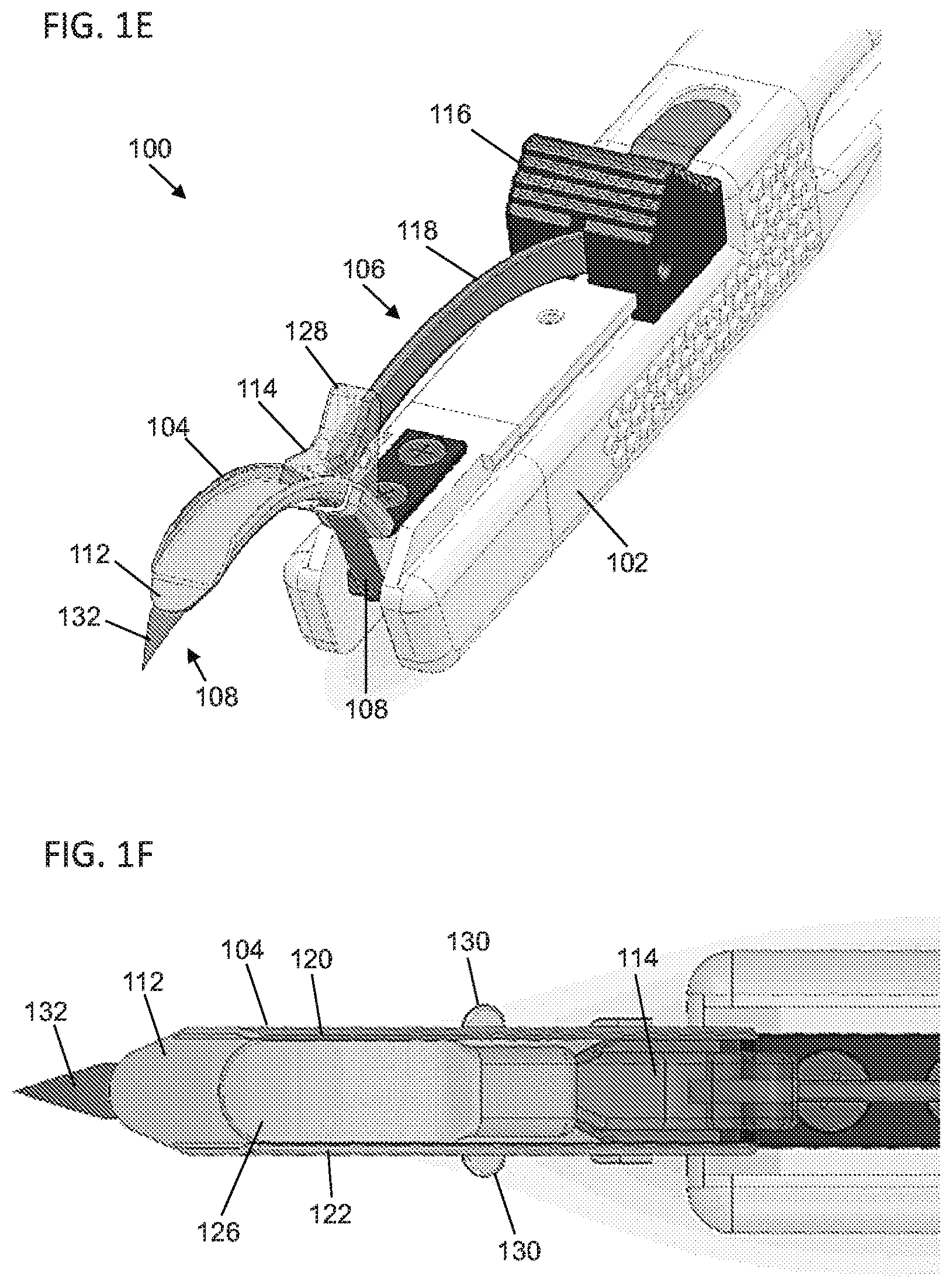
[0040] For example, FIGS. 1A-1H depict one variation of the delivery devices described here. FIG. 1A depicts a perspective view of the delivery device (100), and FIGS. 1B and 1C show a side view and a perspective view, respectively, of a distal portion of the delivery device (100). As shown there, the delivery device (100) may comprise a handle (102) and a tongue member (104) extending from a distal portion the handle (102). In some variations, the delivery device (100) may further comprise an ejector (106), but need not. In variations where the delivery device (100) comprises an ejector (106), the ejector (106) may be configured to deliver an implant from the delivery device (100). Additionally or alternatively, the delivery device (100) may comprise a piercing member (108), but need not. In variations where the delivery device (100) comprises a piercing member (108), the piercing member (108) may have a piercing tip (132) configured to pierce tissue such as the conjunctiva to form an opening therein. In some variation, the delivery device (100) may comprise both an ejector (106) and a piercing member (108). In other variations, the delivery device (100) may comprise an ejector (106), but not a piercing member (108). In these variations, a separate device may be used to form an opening in tissue, as will be described in more detail below, and the tongue member (104) of the delivery device (100) may be advanced through the opening. In still other variations the delivery device (100) may comprise a piercing member (108), but not an ejector (106). In these variations, a separate device may be used to deliver an implant. Each of the components of the delivery device (100) will be described in more detail below.
[0041] Generally, the handle (102) is sized and configured to be held by a user, which may allow the user to manipulate and control the delivery device (100). The handle (102) may have any suitable length (e.g., between about 5 cm and about 20 cm, between about 10 and about 15 cm, or the like) and diameter (e.g., between about 0.5 cm and about 4 cm, between about 1 cm and 3 cm, or the like). While shown in FIG. 1A as having a generally squared cross-sectional shape, the handle (102) may have a cross-section having any suitable shape (e.g., circular, oval, rectangular, another polygon, an irregular shape, or the like). Additionally, in some variations the handle (102) may comprise one or more finger grooves (not shown), but need not. Finger grooves may create a grip-like arrangement that allow a user to more easily grasp and hold the delivery device (100). Generally, the handle (102) allows the device to be gripped and manipulated with one hand, such that the device may be operated with a single hand. The various components of the delivery device (100) (e.g., the handle (102), the tongue member (104)) may be formed from any suitable material or materials, such as one or more metals (e.g., stainless steel, titanium, titanium alloys, or the like), one or more biocompatible plastics (e.g., polycarbonate, ABS, or the like), combinations thereof and the like.
[0042] The tongue member (104) may extend from the handle (102) (e.g., a distal portion of the handle as shown in FIG. 1A). Generally, the tongue member (104) is configured to pass between tissues to form a pocket therebetween. In some variations the tongue member (104) may be curved (such as shown in FIG. 1A), but it should be appreciated that in other variations the tongue member (104) may be straight. When the tongue member (104) is curved, it may have any suitable radius of curvature. In some variations, a curved tongue member (104) may have a radius of curvature that corresponds to a radius of curvature of the orbit. In other variations, it may be desirable to have a curved tongue member (104) having a radius of curvature greater than the radius of curvature of the orbit. In these variations, a tip (112) of the tongue member (104) may be used to palpate the orbit or other tissue structures during advancement of the tongue member (104) past the conjunctiva. The radius of curvature of the orbit may be between about 10 mm and about 50 mm, depending at least in part on the patient and the specific portion of the orbit. In some variations, the curved tongue member (104) may have a radius of curvature greater than about 10 mm, between about 10 mm and about 50 mm, between about 20 and 40 mm, about 25 mm, or the like. In some instances, a delivery device (100) may be selected from a plurality of delivery devices (100) having curved tongue members (104) with different radii of curvatures, depending on the patient. In variations where the delivery device (100) comprises a straight tongue member (104), the tongue member (104) may be used to palpate the orbit or other tissue structures during advancement of the tongue member (104).
[0043] In some variations, the tongue member (104) may be configured to dilate an opening formed in tissue, such as the conjunctiva. For example, in the variation of the delivery device (100) shown in FIG. 1A, the width of the tip (112) of the tongue member (104) may be tapered such that the width decreases from a proximal end of the tip to the distal end of the tip. When the tip (112) is advanced through an opening in tissue (such as the conjunctiva), the increasing width of the tip (112) may dilate the opening as the tip passes therethrough. In some variations, the height of the tongue member (104) may also be tapered to further assist in dilation of an opening and/or forming the pocket between tissues. It should be appreciated that in some variations, the tip (112) of the tongue member (104) may not be tapered. Additionally, in some variations it may be preferable to configure the tongue member (104) such that the tip (112) is rounded or otherwise blunt. In these variations, the tongue member (104) may still be able to push or otherwise displace tissue to create a pocket between tissues, but may have a reduced likelihood of cutting or otherwise damaging certain tissue (such as the eyeball) during advancement of the tongue member (104).
[0044] Generally, it may be desirable to allow a user to control the amount that the tip (112) of the tongue member (104) is advanced beyond the tissue opening. For example, in instances where the delivery devices described here are used to position an implant between the lacrimal gland and the frontal process of the orbit, it may be desirable to first position the tip (112) of the tongue member (104) between the lacrimal gland and the frontal process of the orbit. If the tongue member (104) is not advanced far enough, the implant may not reach the target location on the lacrimal gland. Conversely, if the tongue member is advanced too far, the implant may be placed beyond the lacrimal gland. Accordingly, in some variations the tongue members (104) described here may comprise one or more features to assist a user in controlling the advancement of the tongue member (104) through tissue.
[0045] In some variations, the tongue member (104) may comprise one or more depth stops which may stop or otherwise hinder advancement of the tongue member (104) relative to tissue. For example, in the variation of the delivery device (100) shown in FIGS. 1A-1H, the tongue member (104) may comprise one or more projections (130) extending from one or both sides of the tongue member (104). For example, FIG. 1F shows a top view of a distal portion of the delivery device (100), and as shown there, the tongue member (104) may comprise a projection (130) extending from each side of the tongue member (104). In other variations, the tongue member (104) may comprise one projection (130) extending from only one side of the tongue member (104). Generally, the projections (130) may increase the width of the tongue member (104), and may engage tissue during advancement of the tongue member (104). For example, when the tongue member (104) is advanced through an opening formed in the conjunctiva, the opening of the conjunctiva may fit closely enough around the tongue member (104) during advancement of the tongue member (104) such that the projections (130) may catch on or otherwise press against the conjunctiva. This engagement between the projections (130) and the conjunctiva may resist advancement of the projections (130) past the opening of the conjunctiva. Distance between the tip (112) and the projections (130) may set the distance the tip (112) of the tongue member (104) will be advanced into the orbit when the projections (130) engage tissue. Accordingly, a user may advance the tongue member (104) until the projections (130) resist further advancement, which may indicate to the user how far the tip (112) of the tongue member (104) has been advanced. For example, the projections (130) may be positioned such that the tip (112) of the tongue member is positioned between the lacrimal gland and the frontal process of the orbit when the projections (130) engage an opening in the conjunctiva.
[0046] While the projections (130) are shown in FIGS. 1A-1H as being fixed relative to the tongue member, in other variations the projections (130) may be adjustable relative to the tongue member (104). When the projections (130) are adjustable relative to the tongue member (104), a user may adjust the positioning of the projections (130) to control a penetration depth of the tip (112) of the tongue member (104). Additionally, while shown in FIG. 1A as comprising projections, the tongue member (104) may comprise any suitable structure to help control the advancement of the tongue member (104). For example, in some variations the tongue member (104) may comprise a distal portion and a proximal portion having a larger width than the proximal portion. In these variations, the distal portion tongue member (104) may be advanced through a tissue opening until the proximal portion of the tongue member (104) catches on the tissue opening. In other variations, the tongue member (104) may comprise one or more notches along the tongue member. In these variations, when the tongue member (104) is advanced far enough through a tissue opening such that the notches reach the opening, the tissue opening may contract (e.g., due to elasticity of the tissue) into the notches and may resist further advancement. In still other variations, the tongue member (104) may comprise one or more markers positioned along the length of the tongue member (104). In these variations, a user may advance the tongue member (104) through a tissue opening until a specific marker reaches the tissue opening, at which point the user may know that the tip (112) of the tongue member (104) has been advanced a depth indicated by that marker. It should also be appreciated that the delivery devices described here need not comprise any depth stops or markers.
[0047] As mentioned above, in some variations the delivery device (100) may comprise an ejector. In these variations, the ejector (106) may cooperate with the tongue member (104) to deliver an implant. For example, in the variation of the delivery device (100), the ejector (106) may comprise a pusher (114), a control slider (116), and a linkage (118) connecting the pusher (114) to the control slider (116). The pusher (114) may be slidably connected to the tongue member (104), and the control slider (116) may be slidably connected to the handle (102). A user may advance the control slider (116) relative to the handle (102), and the connection between the control slider (116) and the pusher (114) provided by the linkage (118) may cause advancement of the pusher (114) along the tongue member (104). Similarly, withdrawal of the control slider (116) relative to the handle (102) may proximally withdraw the pusher (114) relative to the tongue member (104).
[0048] In use, the ejector (106) may be used to deliver an implant from the delivery device (100). In some variations, an implant may be slidably connected to the tongue member (104). For example, as shown in FIG. 1C, the tongue member (104) may comprise a first lip (120) on a first side of the tongue member (104) and a second lip (122) on an opposite side of the tongue member (104). The first lip (120) and the second lip (122) may form a track (124) along at least a portion of the length of the tongue member (104). In the variation of the delivery device (100) shown in FIG. 1A, the first lip (120), the second lip (122) and corresponding track (124) may extend along the tongue member (104) from the handle (102) to a proximal end of the tip (112). In other variations, the first lip, second lip, and track may extend along the entire length of the tongue member (104).
[0049] When the tongue member (104) comprises a track (124), the pusher (114) of the ejector (106) may be slidably connected to the tongue member (104) along the track (124). Additionally, as shown in a perspective view in FIG. 1D and a top view in FIG. 1F, an implant (126) may be positioned such that it is slidably received in the track (124). In these variations, the implant (126) may be positioned such that the first lip (120) and the second lip (122) may hold the implant (126) in engagement with the tongue member (104). To deliver the implant (126) from the tongue member (104), the pusher (114) may be advanced (e.g., by advancing the control slider (116)) into contact with the implant (126) and may be further advanced to push the implant (126) along the track (124) until the implant (126) clears the track (124) and is thereby released from the tongue member (104).
[0050] In some variations in which the delivery device (100) comprises an ejector (106) having a pusher (114), the pusher (114) may comprise one or more structures that may be configured to limit advancement of the pusher (114) relative to tissue. For example, in the variation of the delivery device (100) shown in FIGS. 1A-1F, the pusher (114) may have a stop portion (128) having a height sufficient to stop advancement of the pusher (114) relative to a specific tissue structure. For example, when the delivery device (100) is used to advance the tongue member (104) between the eyeball and the frontal process of the orbit, the stop portion (128) may be dimensioned to contact the orbital fossa (e.g., the supraorbital process) when the pusher (114) is advanced along the tongue member (104). When the tongue member (104) is advanced between the eyeball and the orbital fossa to position the tip (112) of the tongue member (104) at a target position, the pusher (114) may be advanced (e.g., via advancement of the control slider (116)) until the stop portion (128) contacts the orbital fossa. At this point, the pusher (114) may be stopped from forward movement relative to the orbital fossa (e.g., which may prevent or resist the pusher (114) from moving between the eyeball and the frontal process of the orbit), but continued advancement of the control slider (116) relative to the handle (102) may cause retraction of the handle (102) and tongue member (104) relative to the tissue. The retraction of the tongue member (104) may pull some or all of the tongue member (104) out of the tissue opening, but the engagement between the pusher (114) and the implant (126) may prevent the implant (126) from being withdrawn, and may result in delivery of the implant (126) from the delivery device.
[0051] As mentioned above, in some variations the delivery device (100) may comprise a piercing member (108) configured to form an opening in tissue such as the conjunctiva. In some variations where the delivery device (100) comprises a piercing member (108), the piercing member (108) may be selectively moveable between a retracted configuration and a piercing configuration. For example, in the variation of the delivery device (100) shown in FIGS. 1A-1F, the piercing member (108) may be selectively moveable between a retracted configuration (such as shown in FIG. 1C), in which a piercing tip (132) of the piercing member (108) is retracted relative to the tip (112) of the tongue member (104), and a piercing configuration (as shown in FIGS. 1E and 1F), in which the piercing tip (132) of the piercing member (108) extends beyond the tip (112) of the tongue member (104). In these variations, the piercing member (108) may be placed in a piercing configuration, and the delivery device (100) may be advanced to drive the piercing tip (132) of the piercing member (108) through tissue (such as the conjunctiva) to form an opening therein. Once the opening has been formed, the piercing member (108) may be placed in the retracted configuration, which may help prevent the likelihood that the piercing member (108) damages tissue beyond the tissue opening.
[0052] The piercing member (108) may be moveable between piercing and retracted configurations in any suitable manner. For example, in some variations, the handle (102) may comprise one or more controls which may be configured to move the piercing member (108) between the piercing and retracted configurations. In variations where the delivery device comprises an ejector, one or more portions of the connector may be configured to move the piercing member (108) between the piercing and retracted configurations.
[0053] In variations where the delivery devices described here comprise both an ejector configured to advance an implant and a piercing member, it may be desirable to configure the delivery device such that the piercing member is prevented from moving to a piercing configuration while the ejector is delivering an implant. For example, in the variation of the delivery device (100) shown in FIGS. 1A-1F, the control slider (116) of the ejector (106) may be configured to control both delivery of the implant (126) and movement of the piercing member to a piercing configuration. Specifically, the control slider (116) may be configured such that advancement of the control slider (116) advances the pusher (114) to advance and deliver an implant (126) (such as described above), while retraction of the control slider (116) may contact a mechanism to move the piercing member (108) to a piercing configuration. Because the control slider (116) requires retraction to move the piercing member (108) to a piercing configuration and advancement to deliver the implant, a user may be prevented from inadvertently moving the piercing member (108) to a piercing configuration when the user is advancing the control slider (116) to deliver an implant.
[0054] FIGS. 1G and 1H depict cross-sectional side views of the delivery device (100) depicting an illustrative mechanism by which retraction of the control slider (116) may move the piercing member (108) to a piercing configuration. In this variation, the handle (102) may comprise a rocker (134) that is pivotably mounted to the handle (102). A first end (136) of the rocker (134) may be connected to the piercing member (108), and may be configured such that the rocker (134) may be rotated relative to the handle (102) in a first direction to a first position (as shown in FIG. 1G), wherein rotation in the first direction to the first position advances the piercing member (108) relative to the tongue member (104) (e.g., to advance the piercing tip (132) of the piercing member (108) past the tip (112) of the tongue member (104) to place the device in the piercing configuration). The rocker (134) may be further configured such that the rocker (134) may be rotated relative to the handle (102) in a second direction opposite the first direction to a second position (as shown in FIG. 1H), wherein rotation of the rocker (134) in the second direction retracts the piercing member (108) relative to the tongue member (104) (e.g., to move the piercing member (108) to the retracted configuration). The handle (102) may further comprise a spring (138) (not shown in FIG. 1G) that pushes against the rocker (134) to bias the rocker (134) toward the second position, thereby biasing the piercing member (108) toward the retracted configuration.
[0055] The control slider (116) may be configured such that retraction of the control slider (116) along the handle (112) moves the control slider (116) into contact with a second end (140) of the rocker (134). The control slider (116) may press against the second end (140) of the rocker (134) to overcome the biasing force provided by the spring (138), and this may rotate the rocker (134) in the first direction and move the piercing member (108) to the piercing configuration (as shown in FIG. 1G). Subsequent advancement of the control slider (116) may disengage the control slider (116) from the rocker (134), thereby allowing the spring (138) to rotate the rocker (134) in an opposite direction to return the piercing member (108) to the retracted configuration (as shown in FIG. 1H). In this variation, in order to advance the control slider (116) to deliver an implant (as discussed above), the control slider (116) needs to be moved out of engagement with the rocker (134). Since the spring (138) biases the delivery device to the retracted configuration when the control slider (116) is not in contact with the rocker (134), a user may be prevented from advancing the control slider (116) and delivering an implant with the piercing member (108) in an extended configuration.
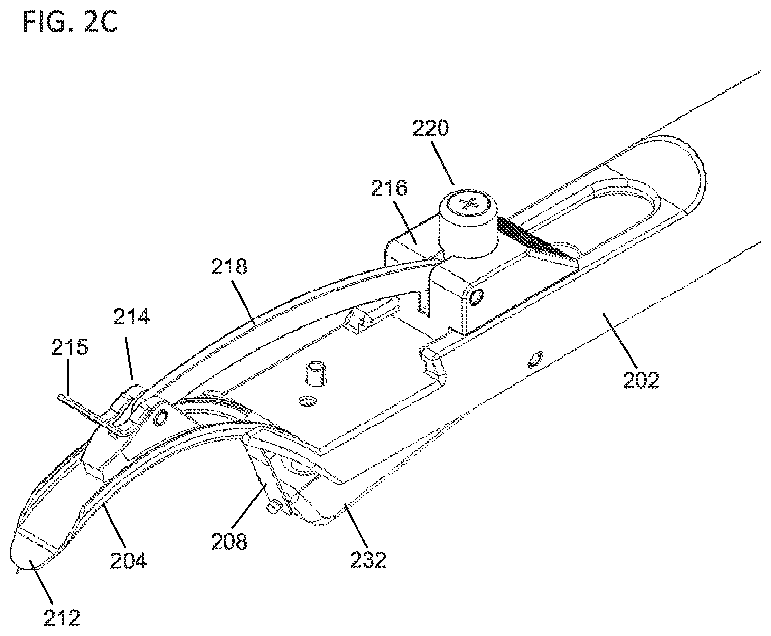
[0056] FIGS. 2A-2E depict a second variation of a delivery device (200) which may also be configured to prevent a piercing member from being moved to a piercing configuration during delivery of an implant. FIG. 2A show a perspective view of the delivery device (200), while FIGS. 2B and 2C show a side view and a perspective view, respectively, of a distal portion of the delivery device (200). As shown there, the delivery device may comprise a handle (202), a tongue member (204), an ejector (206), and a piercing member (208), such as described in more detail above. The tongue member (204) and handle (202) may be configured in any suitable manner, such as described in more detail above. As shown there, the ejector (206) may comprise a pusher (214) slidably connected to the tongue member (204), a control slider (216) slidably connected to the handle (202), and a linkage (218) connecting the pusher (214) and the control slider (216). In some variations, the pusher (214) may comprise a stop member (215) attached thereto, such as described above. Advancement and retraction of the control slider (216) may advance and retract, respectively, the pusher (214) relative to the tongue member (204), as described in more detail above. In the variation of the delivery device (200) show in FIGS. 2A-2E, the control slider (216) may comprise a button (220) which may move the piercing member (208) from a retracted configuration (in which a piercing tip (210) of the piercing member (208) is retracted relative to a tip (212) of the tongue member (204)) to a piercing configuration (in which the piercing tip (210) of the piercing member (208) is advanced beyond the tip (212) of the tongue member (204)).
[0057] FIGS. 2D and 2E depict an illustrative mechanism by which the button (220) of the control slider (216) may be used to move the piercing member (208) from a retracted configuration to a piercing configuration. The handle (202) may comprise a rocker (232) that is pivotably mounted to the handle (202). A first end (234) of the rocker (232) may be attached to the piercing member (208), and the rocker (232) may be rotated in a first direction toward a first position, wherein rotation of the rocker (232) to the first position may advance the piercing member (208) relative to the tongue member (204) to move the piercing member (208) to the piercing configuration as described above (and as shown in FIG. 2E). The rocker (232) may also be rotated in a second direction opposite the first direction toward a second position, wherein rotation of the rocker (232) to the second position may retract the piercing member (208) relative to the tongue member (204) to move the piercing member (208) to the retracted configuration as describe above (and as shown in FIG. 2D). In some variations, the handle (202) may further comprise a spring (236) which may bias the rocker (232) toward the second position, thereby biasing the piercing member (208) toward the retracted configuration.
[0058] In order to move the piercing member (208) to the piercing configuration, a user may depress the button (220). The button (220) may be configured such that depression of the button presses against a second end (236) of the rocker (232) to rotate the rocker (232) in the first direction toward the first position, thereby moving the piercing member (208) to the piercing configuration as discussed above. When the user releases the button (220) (the button (220) may be spring-biased towards an un-depressed position, the spring (236) may return the rocker (232) to the second position, thereby returning the piercing member (208) to the retracted configuration.
[0059] In some variations, the delivery device (200) may be configured such that the button (220) may not be depressed during delivery of an implant. For example, in some variations, the control slider (216) of the ejector (206) may be moveable relative the handle (202) between a retracted position (in which the pusher (214) of the ejector is retracted relative to the tongue member (204)) and an advanced position (in which the pusher (214) of the ejector is advanced relative to the tongue member (204)). As discussed in more detail above, advancement of the control slider (216) and the pusher (214) may advance and deliver an implant (not shown). In order to prevent the button (220) from accidentally being depressed during delivery of the implant, the delivery device (200) may be configured such that the button (220) may be depressed when the control slider (216) is in the retracted position (shown in FIG. 2E), and may further be configured such that the button (220) cannot be depressed when the control slider (216) is outside of the retracted position (e.g., when the control slider (216) is in the advanced position). For example, as shown in FIGS. 2D and 2E, the button (220) may be configured to contact the second end (236) of the rocker (232) through an opening (238) in the handle (202). This opening (238) may be configured such that the button (220) may only be depressed when the button (220) is positioned over the opening (238), and the device may be further configured such that button (220) is positioned over the opening (238) only when the control slider (216) is in the retracted position.
[0060] The delivery device (200) may further be configured such that the control slider (216) may be prevented from advancing while the button (220) is depressed. For example, when the button (220) is depressed into the opening (238) as shown in FIG. 2E, the portion of the button (220) positioned in the opening (238) may be prevented from advancing relative to the handle (202) by a distal end of the opening (238). This in turn may prevent advancement of the control slider (216) while the button (220) is depressed into the opening (238). Accordingly, to advance the control slider (216) from the retracted position, a user may need to release the button (220), which may cause the piercing member (208) to return to the retracted configuration. In this way, the control slider (216) may only be advanced when the button (220) is not pressed (and the piercing member (208) is in the retracted configuration), and the button (220) may be prevented from inadvertently moving the piercing member (208) to the piercing configuration during advancement of the control slider (216).
[0061] In some variations, the delivery devices described here may be configured to absorb blood or other fluids that may escape through a tissue opening as the delivery device is advanced through the opening. For example, in some variations, one or more of the components of the delivery devices described above may be at least partially covered with or otherwise contain a fluid-absorbing material (e.g., one or more porous or sponge materials, one or more woven or non-woven materials, one or more pulps, or the like, which may be formed from collagen, wood pulp, rayon, cotton, or the like). In some variations, one or more portions of a tongue member may be at least partially covered with an absorbent material, such that the tongue member may be configured to absorb fluid contacted by the tongue member. Additionally or alternatively, in variations where the tongue member comprises an ejector having a pusher, one or more portions of the tongue may be covered with an absorbent material.
[0062] FIGS. 6A and 6B depict a variation of a delivery device (600) described here which may be configured to absorb fluid. As shown there, the delivery device (600) may comprise a handle (602) and a tongue member (604) having a tip (612). The delivery device (600) may further comprise an ejector (606) comprising a pusher (614), control slider (616), and linkage (618) and/or a piercing member (not shown), such as described in more detail above. Additionally, in some variations the tongue member (604) may comprise projections (630) or other depth stops as discussed above, but need not. Also shown in FIGS. 6A and 6B is an absorbing member (620). The absorbing member (620) is generally configured to absorb fluid, and may be at least partially formed from one or more of the materials discussed above. The absorbing member (620) may be configured such that it may be slidably connected to the tongue member (604). For example, in some variations the absorbing member (620) may comprise a slot or channel that may be placed at least partially around the tongue member (604) to slidably couple the absorbing member (620) thereto. In these variations, when the tongue member (604) is advanced through an opening in tissue (such as the conjunctiva), the absorbing member (620) may be pressed against the tissue opening. When pressed against the opening, the absorbing member (620) may absorb fluid (e.g., blood) that exits the tissue opening. As the tongue member (604) is further advanced relative to the tissue opening, the absorbing member (620) may be too large to fit through the opening and the tongue member (604) may slide relative to the absorbing member (620). Accordingly, the tongue member (604) may be advanced into the opening while maintaining the absorbing member (620) at the tissue opening.
[0063] In variations where the tongue member (604) comprises projections (630), such as shown in FIGS. 6A and 6B, the projections (630) may be configured to catch against a proximal end of the absorbing member (620), when the tongue member (604) is advanced relative to the absorbing member (620). In these variations, when the projections (630) contact the absorbing member (620), the projections (630) may resist advancement relative to the absorbing member (620). If the absorbing member (620) is positioned against the tissue opening, the absorbing member (620) may be prevented from further advancement, which may in turn resist further advancement of the projections (630) and the tongue member (604). In other variations, the projections (630) may be configured to advance through the absorbing member (620) (e.g., through one or more lumens or channels (not shown) in the absorbing member (620)) as the tongue member (604) is advanced, and the projections (630) may directly engage the tissue opening, as described in more detail above.
[0064] As mentioned above, in some variations, the delivery devices described here do not comprise a piercing member. In some of these variations, the systems described here may comprise a second device that may be used to form an opening in tissue such as the conjunctiva. For example, FIGS. 3A and 3B illustrate a variation of a device configured to puncture or cut a tissue (e.g., the conjunctiva) to form an opening therein. FIG. 3A shows a side view of the piercing device (300). As shown there, the piercing device (300) may comprise a first blade member (302) rotatably connected to a second blade member (304) via a pivot point (306). The first (302) and second (304) blade members may each have an inner edge (305), an outer edge (307), and a tip (309), and may cooperate to create an opening in tissue (such as the conjunctiva). In some instances, the first (302) and second (304) blade members may be used to expand the opening, as will be described in more detail below. Specifically, to create an opening in the tissue, the first (302) and second (304) blade members may be positioned in a first configuration (e.g., by rotating the first blade member (302) relative to the second blade member (304)) in which the tips (309) of the first (302) and second (304) blade members are aligned and coincide to form a point (308), as shown in a side view in FIG. 3B. When the first (302) and second (304) blade members are positioned in the first configuration, the point (308) may be sufficiently sharp to pierce tissue such as the conjunctiva. Accordingly, the first (302) and second (304) blade members may be positioned in the first configuration, and the point (308) may be pressed against a target tissue (e.g., the conjunctiva) to pierce that tissue and form an opening therein. It should be appreciated that in some variations, the first (302) and second (304) blade members may be used to cut tissue and form an opening as the blade members are rotated toward the first configuration, as will be discussed in more detail below, and may be advanced into the opening when in the first configuration.
[0065] Once the point (308) has formed an opening in the target tissue (or the blade members have been inserted in an opening formed in the tissue, such as by cutting the target tissue with the blade members), the first (302) and second (304) blade members may be moved to a second configuration to expand the opening formed in the tissue. Specifically, the first blade member (302) may be rotated relative to the second blade member (304) (e.g., around the pivot point (306)) to move the tips of the first (302) and second (304) blade members away from each other, such as shown in a side view in FIG. 3A. As the first (302) and second (304) blade members move from the first to the second configuration, the outer edges (307) of the blade members move away from each other. The outer edges (307) of the blade members may in turn push against tissue of the opening to stretch or otherwise enlarge the opening in the tissue. With the tissue opening stretched, one or more delivery devices (such as those described above) may be advanced through the opening and may be used to perform one or more additional steps of the methods described here.
[0066] As the outer edges (307) of the blade members are separated, the tissue opening may have a tendency to slide relative to the blade members (e.g., slipping off the front of the piercing device (300) or slipping toward the pivot point (306)). This may interfere with the ability of the first (302) and second (304) blade members to stretch the tissue opening. Accordingly, in some variations, the piercing device (300) may comprise one or more features to help temporarily secure the first (302) and/or second (304) blade members relative to tissue. For example, in some variations, at least one of the first and second blade members comprises a notch. In the variation shown in FIGS. 3A and 3B, each of the first (302) and second (304) blade members comprise a notch (310) in the outer edge (307) of the respective blade members. It should be appreciated, however, that in some variations only the first blade member (302) may comprise a notch (310), only the second blade member (304) comprises a notch (310), or neither of the blade members comprise a notch. Generally, a notch (310) on a blade member may reduce the cross-sectional area of that blade member. When the first (302) and second (304) blade members are placed in a first configuration and advanced to puncture tissue, the piercing device (300) may be further advanced until the notches (310) of the first (302) and second (304) blade members reach the opening. The tissue opening may have an elasticity that may cause the tissue opening to contract into the notches (310). This tension may help hold tissue within the notches (310), and may reduce the likelihood that the tissue opening will slide relative to the first (302) and/or second (304) blade members as the blade members are moved from the first configuration to the second configuration to expand the opening.
[0067] The first (302) and second (304) blade members may be moved between the first and second configurations in any suitable manner. For example, in the variation of the piercing device (300) shown in FIGS. 3A and 3B, each of the first (302) and second (304) blade members may be attached to a first grip and a second grip, respectively (labeled as (312) and (314), respectively). Rotation of the first grip (312) relative the pivot point (306) may rotate the first blade member (302) relative to the pivot point (306), while rotation of the second grip (314) relative to the pivot point (306) may rotate the second blade member (302) relative to the pivot point (306). In the variation shown in FIGS. 3A and 3B, the piercing device (300) may be configured such that rotating the first grip (312) toward the second grip (314) rotates the first blade member (302) toward the second blade member (304) (e.g., toward the first configuration) and rotating the first grip (312) away from the second grip (314) rotates the first blade member (302) away from the second blade member (304) (e.g., toward the second configuration). In other variations, the piercing device (300) may instead be configured such that rotating the first grip (312) toward the second grip (314) rotates the first blade member (302) away the second blade member (304) (e.g., toward the second configuration) and rotating the first grip (312) away from the second grip (314) rotates the first blade member (302) toward from the second blade member (304) (e.g., toward the first configuration). In either of the above embodiments, a user may manipulate the first (312) and second (314) grips to move the first (302) and second (304) blade members between the first and second configurations.
[0068] In some variations, the piercing device may be biased toward one of the first and second configurations. For example, in the variation shown in FIGS. 3A and 3B, the piercing device (300) may comprise a spring member (316) connecting the first (312) and second (314) grips. As shown there, the spring member (316) may bias the first (312) and second (314) grips away from each other, which in turn may bias the first (302) and second (304) blade members toward the second configuration. In these instances, a user may squeeze the first (312) and second (314) grips together to overcome the biasing force provided by the spring member (316) and position the first (302) and second (304) blade members together in the first configuration. Releasing or otherwise reducing the squeezing force applied to the first (312) and second (314) grips may allow the spring member (316) to move the first (302) and second (304) blade members toward the second configuration. It should be appreciated that in some variations, the piercing device (300) may comprise a spring member that is configured to bias the first and second grips toward each other, which in turn may bias the first and second blade members toward the first configuration. In still other variations, the piercing device need not be biased toward any particular position.
[0069] The piercing device may further be configured to limit the range of motion of the first (312) and second (314) grips, which thereby limits the range of motion of the first (302) and second (304) blade members. For example, in the variation shown in FIGS. 3A and 3B, the piercing device (300) may comprise two range-limiting elements. Specifically, one of range-limiting element may limit how closely the first grip (312) may be rotated toward the second grip (314) and the other range-limiting element may limit how far the first grip (312) may be rotated away from the second grip (314). It should be appreciated that in some variations, the piercing device (300) may comprise only a range-limiting element configured to limit rotation of the first grip (312) toward the second grip (314), may comprise only a range-limiting element configured to limit rotation of the first grip (312) away from the second grip (314), or may not comprise any range-limiting element.
[0070] The range-limiting elements may be any structure suitable to limit the rotation of the first grip (312) relative to the second grip (314). In the variation shown in FIGS. 3A and 3B, the piercing device (300) comprises a range-limiting pin (318) positioned between the first (312) and second (314) grips. The range-limiting pin (318) may be attached to one of the grips (e.g., the first grip (312) in the variation shown in FIGS. 3A and 3B) and may act as a stop to rotation of the first grip (312) toward the second grip (314). For example, as shown in FIG. 3B, the first grip (312) may be rotated toward the second grip (314) until the range-limiting pin (318) contacts the second grip (314). This contact between the range-limiting pin (318) and the second grip (314) may prevent the first grip (312) from rotating further toward the second grip (314). In some variations, the range-limiting pin (318) may be configured such that it stops rotation between the first (312) and second (314) grips when the first (302) and second (304) blade members reach the first configuration. In this way, a user may position the first (302) and second (304) blade members in the first configuration by squeezing the first (312) and second (314) grips toward each other until the range-limiting pin (318) prevents further rotation of the grips. This may also act to prevent the first (302) and second (304) blade members from over-rotating past the first configuration.
[0071] Additionally, the piercing device (300) may comprise a range-limiting bar (320) which may limit rotation of the first grip (312) away from the second grip (314). Specifically, the range-limiting bar (320) may be attached to either of the grips (in the variation shown in FIGS. 3A and 3B, the range-limiting bar (320) may be attached to the second grip (314)) and may act as a stop to limit rotation of the first grip (312) away from the second grip (314). For example, the first grip (312) may be free to rotate away from the second grip until it contacts the range-limiting bar (320) (as shown in FIG. 3A). Contact between the range-limiting bar (320) and the first grip (312) may prevent further rotation of the first grip (312) away from the second grip (314). Accordingly, the range-limiting bar (320) may control how far the first (312) and second (314) grips may be separated. This in turn may control how far the first (302) and second (304) blade members may be separated when in the second configuration. By controlling the possible separation of the first (302) and second (304) blade members, the range-limiting bar (320) may control the amount that the opening formed by the piercing device (300) may be stretched. For example, when each of the first (302) and second (304) blade members comprise a notch (310), the range-limiting bar (320) may be configured to stop rotation of the first (312) and second (314) grips when the distance between the notch (310) of the first blade member (302) and the notch (310) of the second blade member (304) reaches a certain amount (e.g., between about 4 mm and about 8 mm or the like). In some instances, it may be desirable to dilate the opening sufficiently to allow for introduction of one or more portions of a delivery device through the opening. When the tissue is engaged in the notches (310), the controlled separation between the notches may provide a predictable, controlled amount of expansion of the opening.
[0072] To use the piercing device (300), a user may initially manipulate the first and second grips to position the first and second blade members in the first configuration (as described above). In the variation shown in FIG. 3B, this may include rotating the first grip (312) toward the second grip (314) (e.g., by squeezing the first and second grips together). When the piercing device comprises a range-limiting element that limits the amount that the first grip (312) may be rotated toward the second grip (314) (such as range-limiting pin (318) depicted in FIGS. 3A and 3B), placing the first and second blade members in the first configuration may comprise rotating the first and second grip members toward each other until the range-limiting element prevents further rotation of the grip members. The user may hold the piercing device (300) in the first configuration, and may advance the point (306) through tissue to puncture the tissue and form an opening therein. The first (302) and second (304) blade members may be advanced into the opening until the notches (310) of the first and/or second blade members reach and engage the opening. With the tissue opening engaged by the notch or notches (310), the first and second grips may be moved to position the first and second blade members in the second configuration. For example, in the variation shown in FIGS. 3A and 3B, the user may release the squeezing force applied to first (312) and second (314) grips, and the spring member (316) may cause the first grip (312) to rotate away from the second grip (314). This in turn may cause the first blade member (302) to rotate away from the second blade member (304), which may stretch the opening engaged by the first (302) and second (304) blade members. In variations where the piercing device comprises a range-limiting element that limits the amount that the first grip (312) may rotate away from the second grip (314) (such as the range-limiting bar (320) depicted in FIGS. 3A and 3B)), the range-limiting element may limit the stretching of the opening.
[0073] In some variations, the piercing device (300) may also act as scissors to cut tissue. Specifically, the inner edges (307) of the first (302) and second (304) blade members may be sharpened, such that the inner edges (307) may cut tissue positioned therebetween. For example, the first (302) and second (304) blade members may be positioned in the second configuration, and the piercing device (300) may be positioned with the first (302) and second (304) blade members on either side of a structure to be cut. When the first (302) and second (304) blade members are moved back to the first configuration, the sharpened inner edges (305) of the first (302) and second (304) blade members may cut the structure. In these variations, the first (302) and second (304) blade members may be moved to the first configuration to cut tissue (such as the conjunctiva) to form an opening therein. With the first (302) and second (304) blade members in the first configuration, the tip (308) formed by the blade members may be advanced through the opening, and the first (302) and second (304) blade members may be moved to the second configuration to stretch or otherwise enlarge the opening, as described in more detail above.
[0074] FIGS. 4A-4E depict a variation of a method by which the delivery devices described above may be used to deliver an implant in the orbit (400) between the lacrimal gland (402) and the frontal process (404). As shown there, the method may comprise retracting an eyelid (406), such as shown in FIG. 4A. When the eyelid (406) is retracted it may be retracted using one or more fingers, or using one or more devices. For example, in some variations, a hook member (408) may be used to retract and/or hold the eyelid (406) in a retracted position. It should also be appreciated that in some variations, the method does not comprise retracting the eyelid (406), but instead comprises piercing through eyelid (e.g., using one or more of the devices described above).
[0075] The method may further comprise piercing the conjunctiva (410) to form an opening therein. In some variations, a delivery device (411) comprising a piercing member (412) may be used to pierce the conjunctiva (410), such as shown in FIG. 4A. The delivery device may be one of the delivery devices described above with respect to FIGS. 1A-1H and 2A-2E. In variations where the piercing member (402) is moveable between a retracted configuration and a piercing configuration (such as described in more detail above), the piercing member (412) may be moved to the piercing configuration, and a piercing tip of the piercing member (412) may be advanced through the conjunctiva (410) to form an opening therein. In other variations, the delivery device (411) does not form the opening in the conjunctiva, but instead a piercing device (such as those described above with respect to FIGS. 3A and 3B) may be used to form the opening in the conjunctiva, in a manner as discussed in more detail above.
[0076] In some variations, the method may further comprise dilating the opening formed in the conjunctiva (410). In variations where a piercing member (412) of the delivery device (411) is used to form the opening in the conjunctiva, the delivery device (411) may be further advanced into the opening of the conjunctiva to begin advancing a tongue member (414) of the delivery device (411) into the opening. As the tongue member (414) is advanced into the opening, the tongue member (414) may dilate the opening in the conjunctiva (410) as described above. For example, when the tongue member (414) has a tapered tip, advancement of the tip through the opening may dilate the opening. In variations where a piercing device forms the opening in the conjunctiva (410), the piercing device may also dilate the opening in the conjunctiva (e.g., by rotating a first blade member relative to a second blade member, such as described in more detail above.
[0077] As shown in FIG. 4B, the tongue member (414) may be advanced through the opening in the conjunctiva to form a pocket between tissues beyond the conjunctiva. In variations where the tongue member (414) comprises a piercing member (411), the piercing member (411) may be placed in a retracted configuration during advancement of the tongue member (414). In variations where a piercing device is used to form the opening in the conjunctiva, the piercing device may be removed once the tongue member (414) has been inserted into the opening. The tongue member (414) may be advanced to position a tip of the tongue member (414) at a target position in the orbit (e.g., between the lacrimal gland (402) and the frontal process (404) of the orbit (400)). In variations where the delivery device comprises one or more depth stops or markers, the tongue member (414) may be advanced until the depth stops or markers reach the opening in the conjunctiva (410), which may control the depth of insertion of the tongue member (414).
[0078] Once the tongue member (414) has been advanced to form a pocket, the delivery device (400) may deliver an implant (416) into the pocket. For example, in variations where the delivery device (400) comprises an ejector (418) (such as described in more detail above), the ejector (418) may deploy the implant (416) (which may be pre-loaded into the delivery device (411)). For example, a control slider (420) of the ejector (418) may be advanced relative to the delivery device (411) to advance a pusher (422) along the tongue member (414). The pusher (422) in turn may push against the implant (416) to begin deploying the implant (416) from the tongue member (414), such as shown in FIG. 4C. In some variations, advancement of the pusher (422) may be advanced until it contacts the frontal process (404), the supraorbital process (407), and/or the upper eyelid as shown in FIG. 4C. In these variations, engagement between the pusher (422) and the bone may prevent further advancement of the pusher (422). Continued advancement of the control slider (420) relative to the delivery device (411) may instead cause the tongue member (414) to be retracted relative the orbit (400), which may result in release of the implant into the pocket formed by the tongue member (414), such as shown in FIG. 4D.
[0079] Following delivery of the implant (416), the devices may be removed from the orbit (400), and the opening in the conjunctiva may be closed, as described above. In some variations, the method may further comprise testing the functionality of the implant. For example, in some variations the delivery devices described here may be configured to provide one or more test signals to the implant (e.g., in instances where the implant comprises a stimulator) which may test whether the implant is properly positioned and/or is functioning properly.
[0080] FIG. 7 depicts a delivery system (700) for delivering an implant (1100) to an orbit of a patient. As shown there, the system may comprise a cannula (702), a spacer (704), a tongue (706), and a plunger (708) (although, as discussed in more detail below, the delivery system may comprise a plunger that may act as both a spacer and a plunger). Generally, the cannula (702) may be used to form an opening in a tissue (e.g., an opening in the conjunctiva, an opening in the eyelid and the conjunctiva, or the like) and may separate tissue beyond the opening to a pocket in the tissue (e.g., the pocket may be formed between the periosteum and the orbital bone, between the periosteum and the lacrimal gland, or the like). The spacer (704) may be advanced through a portion of the cannula and into the tissue opening. As the spacer (704) is advanced through the tissue opening, the spacer (704) may expand the tissue opening and the pocket. The tongue (706) may be advanced through the cannula and through the tissue opening, and may further separate tissue to extend the length of the pocket. With the tongue (706) is positioned through the tissue opening, the spacer (704) may be removed and an implant may be advanced through the cannula (702) using the plunger (708). The plunger (708) may also advance the implant through the tissue opening to position the implant in the pocket. Once the implant is positioned in the pocket, the components of the delivery device may be withdrawn from the body, and the tissue opening may be closed in any manner such as discussed above. The components of the delivery system (700), as well as the steps of using the delivery system (700) to deliver an implant, will each be described in more detail below.
[0081] FIGS. 8A-8C show perspective, top, and side views, respectively, of a variation of the cannula (702) of the delivery system (700) of FIG. 7. As shown there, the cannula (702) may comprise a top wall (800), bottom wall (802) and first and second side walls (each labeled as (804)), which together may define a channel (806) extending between an inlet (808) and an outlet (810). While the top wall (800) only extends partially along the channel (806) in the variation shown in FIGS. 8A-8C, it should be appreciated that in other variations the top wall (800) may extend along the entire length of the channel (806). The channel (806) may allow for the cannula (702) to guide one or more components relative to the cannula (702), as will be described in more detail below. Each of the walls of the cannula (702) may be formed together as a unitary piece, or some walls may be formed separately and attached (e.g., via bonding, welding, or the like). For example, in some variations, the bottom wall (802) and the first and second side walls (804) may be formed together as a single piece, and the top wall (800) may be formed separately from and may be subsequently attached to the side walls (804). In some of these variations, the bottom wall (802) and the first and second side walls (802) may be formed from a first material or materials (e.g., one or more metals, plastics, polymers, or the like), and the top wall (800) may be formed from a second material or materials (e.g., one or more metals, plastics, polymers, or the like) which may be different from the first material or materials.
[0082] Also shown in FIGS. 8A-8C are blade (812) and stop bar (814). The blade (812) may be positioned and arranged to extend beyond the outlet (810) of the channel (806). In the variation shown in FIGS. 8A-8C, the blade (812) may extend from the top wall (800) (e.g., the blade (812) may be formed as part of the top wall (800), or may be formed separately from the top wall (800) and attached thereto). The blade (812) may include a piercing tip (816) configured to puncture tissue to form an opening in tissue (e.g., an opening in the conjunctiva, an opening in the eyelid, or the like). In some variations, the width of the blade (812) may be tapered from the piercing tip (816) (i.e., the width of the blade (812) may increase proximally from the piercing tip (816)), such that advancement of the blade (812) into a tissue opening may expand the tissue opening by increasing the width of the blade (812) positioned in the tissue opening. In some variations, the blade (812) may include one or more cutting edges (818), which may be configured to cut tissue as the blade (812) is advanced into the tissue opening to facilitate dilation of the tissue opening. Additionally, as the blade is inserted past the tissue opening, the blade (812) may separate tissue past the tissue opening to form a pocket in the orbit. In some instances, the blade (812) may be advanced between the periosteum and the orbital bone to form a pocket therebetween. In other instances, the blade (812) may be advanced between the periosteum and another tissue, such as the lacrimal gland, to form a pocket therebetween.
[0083] While shown in FIGS. 8A-8C as having a stop bracket (814), it should be appreciated that the cannula (702) need not comprise a stop bracket (814). In variations where the cannula (702) comprises a stop bracket (814), the stop bracket (814) may be configured to limit the advancement of the blade (812) through tissue. Specifically, the stop bracket (814) may be configured to engage a tissue structure during advancement of the blade (812) through a tissue opening, whereby the engagement between the stop bracket (814) and the tissue structure may limit further advancement of the blade (812) into the tissue opening. For example, when the blade (812) is used to form an opening through an eyelid and/or the conjunctiva (as will described in more detail below), the stop bracket (814) may be configured to engage tissue overlying orbital fossa (e.g., the supraorbital process, the orbital process of the zygomatic bone, or the like) to limit further advancement of the blade when the stop bracket (814) engages the orbital fossa.
[0084] As shown in FIGS. 8A-8C, the stop bracket (814) may extend away from the top wall (800) by a height (H). The height (H) between the stop bracket (814) and the top wall (800) may be any suitable value, such as, for example, about 1 cm, between about 0.75 and about 1.25 cm, at least about 0.75 cm and the like. As used here, "about" means.+-.5%. For example, the height may be configured such that the stop bracket (814) is tall enough to engage tissue of the orbital fossa when the blade (812) is advanced between the eye and the orbital fossa. Additionally, in some variations the stop bracket (814) may be configured to define an aperture (820) between the stop bracket (814) and cannula (702) (e.g., between the stop bracket (814) and the top wall (800) of the cannula (702)). The aperture (820) may be sized and configured to allow one or more components of delivery system (700) to be advanced through the aperture (820) during use of the delivery system (700), as will be described in more detail below.
[0085] In some variations, the stop bracket (814) may be angled relative to the longitudinal axis of the cannula (700), which may facilitate creation of an opening in the left or right orbit of a patient. Specifically, the stop bracket (814) may be angled to accommodate the contours of the left or right orbit to help increase the surface contact between the stop bracket (814) and the orbital fossa during advancement of the cannula (700). As shown in FIG. 8B, the stop bracket (814) may be positioned at an angle (.theta.) relative to the longitudinal axis (822) of the cannula (700) in a clockwise direction. The angle (.theta.) may be any suitable angle. In some variations, the angle (.theta.) may be about 90 degrees, such that the stop bracket (814) is perpendicular to the longitudinal axis (822) of the cannula (700). In these variations, the cannula (700) may be used to form an opening in either the left orbit or the right orbit, as a similar amount of the stop bracket (814) will contact each orbit when a blade (812) is inserted between the eye and the orbital fossa. In other variations, the angle (.theta.) may be less than 90 degrees. For example, in the variation shown in FIG. 8B, the angle (.theta.) may be about 45 degrees. An angle (.theta.) less than 90 degrees may increase the contact area between the stop bracket (814) and the orbital fossa of a patient's right orbit during advancement of the blade (812) into the right orbit. Conversely, in other variations, the angle (.theta.) may be greater than 90 degrees, which may facilitate the formation of a tissue opening in the left orbit. For example, in some variations, the angle (.theta.) may be about 135. An angle (.theta.) greater than 90 degrees may increase the contact area between the stop bracket (814) and the left orbit during advancement of the blade (812) into the left orbit. It should be appreciate that, depending on the intended angle of insertion of the blade (812) relative to tissue, the angled stop brackets (814) may be used to facilitate formation of tissue openings in either orbits. For example, a cannula (700) with a stop bracket (814) at an angle (.theta.) greater than 90 degrees may be used to create an opening in the right orbit. In other instances, a cannula (700) with a stop bracket (814) at an angle (.theta.) less than 90 degrees may be used to create an opening in the left orbit.
[0086] Returning to FIG. 7, the delivery system (700) may further comprise a spacer (704). Generally, the spacer (704) may be sized to fit within and extend through the channel (806) of the cannula (702). The spacer (7040 may be advanced through the channel (806) of the cannula to advance a distal end of the spacer (704) distally of the outlet (810) of the cannula (702). This may introduce the distal end of the spacer (704) into the tissue opening, which may dilate or otherwise expand the tissue opening (and in some instances a portion of the pocket). For example, the spacer (704) may have a dilating tip (710) at the distal end of the spacer (704), which may be configured to dilate the tissue opening and pocket formed by the blade (812) of the cannula (702). As shown in FIG. 7, the width and height of the dilating tip (706) may be tapered. In some of these variations, the tapering width of the dilating tip (706) may match the tapering width of the blade (812) of the cannula (702), although it should be appreciated that in some instances the surfaces of the dilating tip (706) may be rounded or otherwise dull to limit the ability of the dilating tip (706) to cut or sever tissue. As the dilating tip (706) is introduced through the tissue opening and into the pocket, the increasing height of the dilating tip (706) may dilate the tissue opening and the pocket.
[0087] In some variations, the spacer (704) may comprise a lip (712). In some variations, the lip (712) may catch or otherwise engage the inlet (808) of the cannula (702) during advancement of the spacer (704) to limit further advancement of the spacer (704). In some variations, the spacer (704) and cannula (702) may be sized such that when the lip (712) engages the inlet (808) of the cannula (702), the distal end of the dilating tip (706) is aligned with the distal end of the blade (812). In variations where the tapering width of the dilating tip (706) matches the tapering width of the blade (812), the edges of the dilating tip (706) may also be aligned with the edges of the blade (812) when the lip (712) engages the inlet (808) of the cannula (702).
[0088] The tongue (706) may be configured for advancement through the channel (806) of the cannula (702) while the spacer (704) is positioned to extend through the channel (806). Accordingly, the tongue (706), the spacer (704) and the channel (806) may each be sized such that the tongue (706) and spacer (704) may simultaneously fit inside the channel (806). As shown in FIG. 7, the tongue (706) may have a tapered tip (714) in which the width of the tongue (706) tapers. In some variations, the tapering width of the tongue (706) may match the tapering width of the dilating tip (706) of the spacer (704) and/or the tapering width of the blade (812) of the cannula (702), but need not. In some variations, the tongue (706) may further comprise a stop (716) configured to limit advancement of the tongue (706) through the channel (806) of the cannula. In some instances, the stop (716) may be a portion of the tongue having an increased width or height (such as a lip, or the like), which may catch on the inlet (808) of the channel (806) to prevent further advancement of the tongue (706) relative to the cannula (702). In some variations, the tongue (706) and cannula (702) may be sized such that when the stop (716) of the tongue (706) engages the inlet (808) of the channel (806) of the cannula (702), the tip of the tongue (706) may extend distally of the blade (812) of the cannula (702). In these variations, the tongue (706) may further separate tissue to extend the length of the pocket. Additionally, in variations where the tongue (706) comprises a tapered tip (714), the tapered width of the tapered tip (714) may facilitate separation of tissue. In other variations, the tongue (706) and cannula (702) may be sized such that when the stop (716) of the tongue (706) engages the inlet (808) of the cannula (702), the distal tip of the tongue (706) may be aligned with the distal tip of the blade (812) of the cannula (702). When the tongue (706) is positioned in the cannula (702), the tongue (706) may aid in insertion of the implant into tissue, as described in more detail below.
[0089] As mentioned above, the delivery system (700) may also comprise a plunger (708) which may be advanced into the channel (806) of the cannula (702) to advance an implant through the channel (806). FIG. 9 shows a side view of one variation of a plunger (708) suitable for use with the delivery system of FIG. 7. As shown there, the plunger (708) may comprise a plunger portion (900) sized and configured to be inserted into the channel (806) of the cannula (702) through the inlet (808). The plunger (708) may further comprise a stopper portion (902) connected to a distal portion of the plunger portion (900) via a transition region (904). The stopper portion (902) may be a portion of the plunger (708) configured to remain outside of the channel (806) when the plunger portion (900) is inserted into the channel (806). For example, in the variation of the cannula (702) shown in FIGS. 8A-8C, the top wall (800) may include a slot (824) extending at least partially along the channel (806) (which in some variations may extend from the inlet (808)). In some variations, the slot (824) may extend along the entire length of the channel (806). When the plunger portion (900) is inserted into the channel (806), the transition region (904) may extend through the slot (824) to position the stopper portion (902) outside of the channel (806). In some instances, the plunger portion (900) and stopper portion (902) may each be wider than the slot (824) of the top wall (800), such that when the transition region (904) is positioned at least partially into the slot (824), the plunger portion (900) may be prevented from exiting the channel (806) through the slot (824) of the top wall (800) and the stopper portion (902) may be prevented from entering the channel (806) through the slot (824) of the top wall (800). Similarly, the transition region (904) may be narrower than the slot (824) to allow the transition region (904) to enter the slot (824) during advancement of the plunger (708).
[0090] In some variations, a distal portion of the stopper portion (902) may extend distally of the distal end of the transition region (904) to define a space (906) between the distal portion of the stopper portion (902) and the plunger portion (900). This space (906) may allow the distal end of the stopper portion (902) to be advanced distally of the distal end of the slot (824) of the top wall (800). Specifically, the distal end of the transition region (904) may prevent further advancement of the plunger (708) relative to the cannula (702) when the distal end of the transition region (904) reaches and engages the distal end of the slot (824). In variations where the distal end of the stopper portion (902) is flush with the distal end of the transition region (904), the distal end of the stopper portion (902) may be aligned with the distal end of the slot (824) when the distal end of the transition region (904) reaches the distal end of the slot (824). In variations where the distal end of stopper portion (902) extends distally of the distal end of the transition region (904), the top wall (800) may be received in the space (906) between the stopper portion (902) and the plunger portion (900) until the distal end of the transition region (904) reaches the distal end of the slot (824) to prevent further advancement of the plunger (708) relative to the cannula (702). At this point, the distal end of the stopper portion (902) may extend distally of the distal end of the slot (824) of the top wall (800). Additionally or alternatively, the plunger (708) may be sized and configured such that a distal end of the plunger portion (900) may extend distally of the outlet (810) of the channel (806) when the transition region (904) reaches the distal end of the slot (824). Additionally, in variations where the cannula (702) comprises a stop bracket (814) having an aperture (820) extending therethrough, a distal portion of the stopper portion (902) may be sized to fit through the aperture (820) of the stop bracket (812), which may allow the stopper portion (902) to be advanced through the aperture (820) during advancement of the plunger (708) relative to the cannula (702).
[0091] While the variation of the delivery system (700) depicted in FIG. 7 is shown as having a plunger (708) that is separate from the spacer (704), it should be appreciated that in other variations the delivery system (700) may include a single member that may act as both a plunger and a spacer. For example, FIG. 10 shows one such variation of a plunger (1000) that may be used with the delivery system (700). As shown there, the plunger (1000) may comprise a first end having a dilating tip (1002). The dilating tip (1002) may be configured in any manner as described above with respect to the dilating tip (710) of the spacer (702) of FIG. 7. In these variations, the first end of the plunger (1000) may be inserted into the channel (806) of a cannula (702) to act as a spacer (704), as will be discussed in more detail below.
[0092] The plunger (1000) may further comprise a second end may be configured to include one or more elements of the plunger (708) described above with respect to FIG. 9. Specifically, the second end of the plunger (1000) may comprise a plunger portion (1004) and a stopper portion (1006) connected to the plunger portion (1004) by a transition region (1008). The plunger portion (1004) of the second end of the plunger (1000) may be inserted into the channel (806) of the cannula (700), and the stopper portion (1006) may be configured to remain outside of the channel (806) when the plunger portion (1004) of the second end is inserted into the channel (806). In some variations, such as shown in FIG. 10, a distal end of the stopper portion (1006) may extend distally of the transition region (1008) to define a space (1010) between the stopper portion (1006) and the plunger portion (1004) of second end of the plunger (1000). In these variations, a portion of the top wall (800) may be received in the space (1010) during advancement of the second end of the plunger (1000) into the channel (806) of the cannula (702). Additionally, a proximal end of the transition region (1008) and/or the stopper portion (1006) may act as a stop to limit advancement of the dilating tip (1002) of the first end of the plunger (1000) into the cannula (700).
[0093] FIGS. 11A-11I depict an illustrative method by which the delivery system (700) described above with respect to FIGS. 7-10 may be used to deliver an implant (1100) to the orbit of a patient. The cannula (702) may be advanced toward the orbit of a patient as illustrated in FIG. 11A, and the blade (812) may be advanced to pierce tissue of the patient to form an opening therein. In some variations, the piercing tip (816) of the blade (812) may puncture the conjunctiva to form a tissue opening in the conjunctiva. In some of these variations, the method may comprise retracting an eyelid prior to piercing the conjunctiva. In other variations, the piercing tip (816) of the blade (812) may puncture the eyelid to form a tissue opening in the eyelid. The blade (812) may be further advanced relative to the tissue opening to separate tissue beyond the opening to form a pocket in the tissue. In some variations, the blade (812) may be advanced between the periosteum and the orbital bone to form a pocket therebetween. In other instances, the blade (812) may be advanced between the periosteum and another tissue, such as the lacrimal gland, to form a pocket therebetween. In variations where the width of the blade (812) tapers, advancement of the blade (812) through the tissue opening may dilate the tissue opening. Additionally, in variations where the cannula (700) comprises a stop bracket (814), the cannula (700) may be advanced to advance the blade (812) into tissue until the stop bracket (814) contacts tissue (e.g., tissue overlying the orbital fossa such as shown in FIG. 11A), which may prevent or otherwise limit further advancement of the cannula relative to tissue.
[0094] With the blade (812) positioned to extend through the tissue opening, the spacer (704) may be introduce into and advanced through the channel (806) of the cannula (700), as illustrated in FIG. 11B, and may be further advanced to position a dilating tip distally of the outlet (810) of the channel (806). This advancement may advance the dilating tip (710) of the spacer (704) through the tissue opening and into the pocket, as illustrated in FIG. 11C. As the dilating tip (710) passes through the tissue opening and into the pocket, the dilating tip (710) may dilate the tissue opening and the pocket. While the dilating tip (710) of the spacer (704) is shown in FIGS. 11B and 11C as expanding the tissue opening and the pocket, it should be appreciated that in some variations, the dilating tip (1002) of the first end of plunger (1000) described above with respect to FIG. 10 may be instead be advanced into the cannula (700) as described above.
[0095] Generally, the dilating tip (710) may be introduced into the channel (806) through an inlet (808) of the channel, advanced through the channel (806), and out of the outlet (810) of the channel (806). In some variations, the dilating tip (710) may be advanced into the pocket until the distal end of the dilating tip (710) is aligned with a distal tip of the blade (812). In some instances, the dilating tip of the spacer (or plunger) may be advanced through the cannula until a portion of the spacer (or plunger) engages the inlet (808) of the channel (806) of the cannula (702). For example, in variations where the spacer (704) comprises a lip (712), the spacer (704) may be advanced through the channel (806) of the cannula (700) until the lip (712) catches on the inlet (808) of the channel (806) (e.g., the engagement between the lip (712) and the inlet (808) may prevent further advancement of the spacer (704) relative to the cannula (700)), such as shown in FIG. 11C. In variations where a dilating tip (1002) of a plunger (1000) is advanced through the cannula, the plunger (1000) may be advanced through the channel (806) of the cannula (700) until a portion of the stopper portion (1006) and/or transition region (1008) of the second end of the plunger (1000) catches on the inlet (808) of the channel (806) (e.g., the engagement between the stopper portion (1006) and/or transition region (1008) and the inlet (808) may prevent further advancement of the plunger (1000) relative to the cannula (700)).
[0096] With the blade (816) of the cannula (700) and the dilating tip of either a spacer or a plunger positioned to extend through the tissue opening, the tongue (706) may be advanced through the channel (806) of the cannula (700), as shown in FIG. 11C, and may be advanced out of the outlet (808) of the channel (806) of the cannula (700) to advance a distal tip of the tongue (706) through the tissue opening and into the pocket, as shown in FIG. 11D. In some of these variations, the tip of the tongue may be advanced distally of the tip of the blade and the dilating tip of the spacer (or plunger), which may further separate tissue to extend the length of the pocket. In some instances, the tongue (706) may be advanced through the cannula (700) between the spacer (or plunger) and the top wall (800) of the cannula. In variations where the tongue (706) comprises a stop (716), the tongue may be advanced until the stop (716) engages the inlet (808) of the channel (806) of the cannula (702), which in turn may control how far the tip of the tongue (706) is advanced into the orbit.
[0097] The spacer (or plunger) may be removed from the tissue opening and channel (806) (e.g., by proximally withdrawing the spacer or plunger relative to the cannula (702)), and the implant (1100) may be inserted into the channel (806) (e.g., by inserting the implant (1100) into the inlet (808) of the channel (806)), such as shown in FIG. 11E. In some instances, the implant (1100) may be positioned between the tongue (706) and the top wall (800) of the cannula (700). With the implant positioned in the channel (806), a plunger portion (900) of the plunger (708) may be advanced into the channel (806), such as shown in FIG. 11F. As shown there, the plunger portion (900) may be positioned between the tongue (706) and the top wall (800), and the stopper portion (902) may be positioned outside of the channel (806) (e.g., the transition region (904) may extend through the slot (824) in the top wall (800) of the cannula). As the plunger (708) is advanced into the channel (806), a portion of the plunger (708) (e.g. the plunger portion (900)) may contact the implant (1100) and push the implant (1100) along the channel (806).
[0098] In some variations, the plunger (708) may advance the implant (1100) until the stopper portion (902) contacts tissue (e.g., tissue overlying the orbital fossa), such as shown in FIG. 11G. In variations where the cannula (702) has a stop bracket (814) defining an aperture (820) extending therethrough, the stopper portion (902) may extend at least partially through the aperture (820) to contact tissue. In some variations, the plunger (708) may be configured such that when the stopper portion (902) of the plunger (708) engages tissue (e.g., to prevent further advancement of the plunger), the plunger portion (900) has advanced the implant (1100) distally of the outlet (810) of the channel (806) of the cannula (702), through the tissue opening, and into the pocket, such as depicted in FIG. 11G. In these variations, the blade (816) and the tongue (706) may guide advancement of the implant (1100) after the implant (1100) has been advanced out of the outlet (810) of the channel (806).
[0099] A user may hold the stopper portion (902) against the patient, and may withdraw the cannula (702) and the tongue (704) relative to the plunger (708) to withdraw the blade (816) and the distal tip of the tongue (704) at least partially from the tissue opening and pocket, such as shown in FIG. 11H. As the cannula (702) and the tongue (706) are withdrawn relative to plunger (708), the plunger portion (900) of the plunger (708) may contact and hold the implant (1100) in place, and thus may prevent the implant (1100) from being withdrawn with the cannula (702) and the tongue (706). In variations where the stopper portion (902) of the plunger (708) extends distally of the transition region (904), the cannula (702) may be withdrawn relative to the plunger (708) until the distal end of the slot (824) engages the transition region (904), at which point further retraction of the cannula (702) relative to the patient may also pull the plunger (708) proximally relative to the patient, such as shown in FIG. 11I, which may disengage the entire delivery system (700) from the patient. It should be appreciated that while the plunger (708) described above with respect to FIG. 9 is depicted in FIGS. 11F-11I as advancing implant (1100), the second end of the plunger (1000) described above with respect to FIG. 10 may be used to advance the implant (1100) in the manner discussed immediately above. Once the delivery system (700) has been removed from the patient, the tissue opening may be closed in any suitable manner such as those discussed above.
[0100] In some instances, one or more components of the delivery systems (700) described above with respect FIGS. 7-10 may be integrated into single device. For example, FIGS. 12A-12I depict a variation a delivery device (1200) as described here. As shown there, the delivery device (1200) may comprise a cannula (1202), a tongue (1204), and a plunger (1206). The cannula (1202) may define a channel (1208) extending between an inlet (1210) and an outlet (1212), and the tongue (1204) and plunger (1206) may be slidably connected to the cannula (1202) to extend at least partially through the channel (1208). In some variations, the outlet (1212) may be angled, such that the height of the channel (1208) increases from a distal end of the outlet (1212) to a proximal end of the outlet (1212). In these variations, the walls of the cannula (1202) defining the outlet (1212) may dilate a tissue opening as the cannula (1202) is advanced into a tissue opening.
[0101] FIG. 12I depicts a top view of the cannula (1202) (the remaining components of the delivery device (1200) are not illustrated in this figure). As shown there, the cannula (1202) may further comprise a top wall (1214) having a slot (1216) extending at least partially along the channel (1208). In some of these variations, the slot (1216) may extend at least partially along the channel (1208) from an inlet (1210) of the channel (1208). A portion of the plunger (1206) may extend through the slot (1216) of the top wall (1214), as will be discussed in more detail below. In some variations, such as shown in FIG. 12I, the slot (1216) may comprise a proximal segment (1234), a distal segment (1236), and an intermediate segment (1238) between the proximal segment (1234) and the distal segment (1236). The width of the intermediate segment (1238) may be wider than the widths of the proximal segment (1234) and the distal segment (1236). In some instances, an implant may be inserted into the channel (1208) of the cannula (1202) via the intermediate segment (1238). In these variations, the width of the intermediate segment (1238) may be greater than a width of the implant, which may allow the implant to enter the channel (1208) through the intermediate segment (1238). In some of these variations, the width of the distal segment (1236) of the slot (1216) may be less than the width of the implant, which may prevent the implant from exiting the channel (1208) through the distal segment (1236) as the implant is advanced through the channel (1208) of the cannula (1202).
[0102] The cannula (1202) may further comprise a blade (1218), which may be configured in any suitable manner such as described above with respect to the blade (812) of the cannula (702) described above with respect to FIGS. 8A-8C above. For example, the blade (1218) may include a piercing tip (1220), which may puncture tissue to form a tissue opening. In some variations, the width of the blade (1218) may be tapered such that the width of the blade (1218) increases proximally from the piercing tip (1220). In these instances, advancement of the blade (1218) into the tissue opening may dilate the tissue opening. The blade (1218) may optionally further comprise one or more cutting edges (1222), which may configured to cut tissue as the blade (1218) is advanced into the tissue opening (which may facilitate expansion of the tissue opening). Additionally, in some variations the cannula (1202) may further comprise a stop bracket (1224), which may be configured as any of the variations of the stop bracket (814) described above with respect to FIGS. 8A-8C. Generally, the stop bracket (814) may extend away from the top wall (1214) by a height which may allow the stop bracket (814) to engage the tissue (e.g., tissue overlying the orbital fossa) during advancement of the blade (1218) into the tissue opening. In some variations, the stop bracket (1224) may comprise an aperture (1226) extending through the stop bracket (1224). A portion of the plunger (1206) may extend through the aperture (1226) during use of the delivery device (1200), as will be discussed in more detail below. Additionally, the stop bracket (814) may be positioned at any angle relative the longitudinal axis of the cannula (1202) as discussed above with respect to the stop bracket (814) of FIGS. 8A-8C.
[0103] As mentioned above, the plunger (1206) may be slidably connected to the cannula (1202). In some variations, the plunger (1206) may comprise a plunger portion (1228) and a stopper portion (1230), wherein the plunger portion (1228) is positioned at least partially in the channel (1208) and the stopper portion (1230) is positioned outside of the channel (1208). The stopper portion (1230) and plunger portion (1228) may be configured in any manner as described above with respect to the plunger portion (900) and stopper portion (902) described above with respect to the plunger (708) of FIG. 9. For example, in some variations, the stopper portion (1230) may be connected to the plunger portion (1228) by a transition region, which may extend through the slot (1216) of the top wall (1214). In some of these variations, the distal end of the stopper portion (1230) may extend distally of the distal end of the transition region to define a space between the distal portion of the stopper portion and the plunger portion.
[0104] In some instances, the stopper portion (1230) and/or the transition region may control the range of motion of the plunger (1206) relative to the cannula (1202). For example, in some variations, a proximal end of the stopper portion (1230) and/or transition region may engage a portion of the cannula (1202) during withdrawal of the plunger (1206) to prevent further withdrawal of the plunger (1206) (which may prevent the plunger (1206) from being removed from the channel (1208) of the cannula (1202)). For example, the cannula (1202) may comprise a projection such as a bar (1232) which may be connected to the cannula (1202). The bar (1232) may be positioned relative to the plunger (1206) such that a proximal end of the stopper portion (1230) of the plunger (1206) contacts the bar (1232) when the plunger (1206) is retracted relative to the cannula (1202), such as shown in FIGS. 12A-12D. The contact between the plunger (1206) and the bar (1232) may prevent further retraction of the plunger (1206) relative to the cannula (1202). Similarly, a portion of the plunger (1206) may limit the distal advancement of the plunger (1206) relative to the cannula (1202). In some variations, the plunger (1206) may be advanced until the transition region contacts a distal end of the slot (1216), which may prevent further advancement of the plunger (1206) relative to the cannula (1202). In variations where a distal end of the stopper portion (1230) extends distally of the distal end of a transition region, the plunger (1206) may be advanced relative to the cannula (1202) until a distal end of the transition region contacts a distal end of the slot (1216), such as shown in FIGS. 12E and 12G. In these variations, the distal end of the stopper portion (1230) may extend distally of the distal end of the slot (1216), and in some instances may extend at least partially through the aperture (1226) of the stop bracket (1224). Additionally or alternatively, the distal end of the plunger portion (1228) may extend distally of the distal end of the slot (1216) when the distal end of the transition region contacts the distal end of the slot (1216). In some of these variations, the distal end of the plunger portion (1228) may extend distally of the outlet (1212) of the channel (1208) when the distal end of the transition region contacts the distal end of the slot (1216).
[0105] It should be also be appreciated that in some instances the delivery device (1200) may be temporarily configured to prevent advancement of the plunger (1206) between the retracted position shown in FIGS. 12A-12D and the extended position shown in FIGS. 12E and 12G. In some variations, the delivery device (1200) may comprise an intermediate stop, which may temporarily limit advancement of the plunger (1206) between the retracted and extended positions. For example, FIGS. 13A-13D depict a variation of the cannula (1202) of the delivery device (1200) of FIGS. 12A-12I with the plunger (1206) and tongue (1204) removed. As shown there, the cannula (1202) may comprise a bumper plate (1300). The bumper plate (1300) may be moveable between a lowered position (as shown in rear and front perspective views in FIGS. 13A and 13C) and a raised position (as shown in rear and front perspective views in FIGS. 13B and 13D). When the bumper plate (1300) is in the lowered position, the bumper plate (1300) may block advancement of the plunger (1206) to the extended position shown in FIGS. 12E and 12G. For example, the plunger (1206) may be advanced with the bumper plate (1300) in the lower position until the stopper portion (1230) reaches and contacts the bumper plate (1300). The engagement between the stopper portion (1230) and the bumper plate (1300) may temporarily prevent further advancement of the plunger (1206) relative to the cannula (1202). Conversely, when the bumper plate (1300) is in the raised position, the stopper portion (1230) may pass under the bumper plate (1300) and may allow the plunger (1206) to be advanced to the extended position.
[0106] The bumper plate (1300) may be moved between the lowered and raised positions in any suitable manner. For example, in some variations the delivery device (1200) may comprise one or more spring elements (1304) connecting the bumper plate (1300) to the cannula (1202). While shown in FIGS. 13A-13D as being a beam springs, the spring elements (1304) may be any suitable spring (e.g., a compression spring, a torsion spring, or the like). Additionally, while shown in FIGS. 13A-13D as having two spring elements (1304), the bumper plate (1300) may comprise any suitable number of spring elements (1304) (e.g., one, two, or three or more). In some variations, the one or more spring elements (1304) may be biased toward the lowered position. In these variations, a control (such as a switch, lever, or the like) may be actuated to lift the bumper plate (1300) to overcome the bias of the one or more spring elements (1304) and raise the bumper plate (1300) to the raised position. In other variations, such as that shown in FIGS. 13A-13D, the one or more spring elements (1304) may bias the bumper toward the raised position. In these variations, a control element may temporarily hold the bumper plate (1300) in the lowered position.
[0107] For example, in the variation of the cannula (1202) shown in FIGS. 13A-13D, the cannula (1202) may comprise a release bracket (1308), which may be position and arranged to temporarily hold the bumper plate (1300) in the lowered position. For example, the release bracket (1304) may comprise one or more projections (1306) or lips, or may otherwise be configured to engage the release bracket (1308) when the bumper plate (1300) is in the lowered position to hold bumper plate (1300) in the lowered position. To move the bumper plate (1300) to the raised position, a user may deflect or otherwise move the release bracket (1308) away from the bumper plate (1300), which may temporarily disengage the release bracket (1308) from the bumper plate (1300). When the release bracket (1308) is disengaged from the bumper plate (1300), the one or more spring elements (1304) may lift the bumper plate (1300) to the raised position. In some variations, the cannula (1202) may optionally further comprise a structure (such as a stop bar (1310)) positioned to contact the bumper plate (1300) and/or the one or more spring elements (1304) to limit the upward motion of the bumper plate (1300), which in turn may control the raised position of the bumper plate (1300).
[0108] In some variations, the bumper plate (1300) may be further configured to temporarily limit advancement of the implant relative to the bumper plate (1300). For example, in the variation of the cannula (1202) shown in FIGS. 13A-13D, the bumper plate (1300) may comprise an extension (1312) positioned and arranged to extend into the channel (1208) when the bumper plate (1300) is in the lowered position. For example, extension (1312) of the bumper plate (1300) may extend through the intermediate segment (1238) and/or the distal segment (1236) of the slot (1216) when the bumper plate (1300) is in the lowered position. When an implant is inserted into the channel (1208) (i.e., through the intermediate segment (1238)), the implant may be advanced until it contacts the extension (1312). The extension (1312) may be sized such that the implant may be prevented from being advanced distally of the extension (1312) when the extension (1312) is positioned in the channel (1208). When the bumper plate (1300) is move to the raised position, the extension (1312) may be removed from the channel (1208), which may allow the implant to be advanced distally of the bumper plate (1300) as will be discussed in more detail below. While the delivery device (1200) is depicted in FIGS. 12A-12I and 13A-13D as having a bumper plate as an intermediate stop, it should be appreciated that in other variations the delivery device (1200) may comprise a plug or other component which may be removably connected to the cannula (1202) to limit advancement of the plunger (1206) to the extended position while the plug is connected to the cannula (1202). The plug may in turn be disconnected from the cannula (1202) to allow further advancement of the plunger (1206). Additionally, the plug may further comprise an extension positioned to extend into the channel (1208) when the plug is connected to the cannula (1202), which may temporarily prevent advancement of an implant relative to the plug, such as discussed above with respect to the extension (1312) of the bumper plate (1300).
[0109] Returning to FIGS. 12A-12H, the delivery device (1200) may comprise a tongue (1204) slidably connected to the cannula (1202), wherein the tongue (1204) extends at least partially through the channel (1208) of the cannula (1202). In some variations, the plunger portion (1228) of the plunger (1206) may be positioned between the tongue (1204) and the top wall (1214) of the cannula (1202). The tongue (1204) may be moved between a retracted position (as shown in FIGS. 12A-12D), in which a distal tip of the tongue (1204) is positioned in the channel (1208), and an advanced position (as shown in FIGS. 12E-12H), in which a distal tip of the tongue (1204) extends distally out of the outlet (1212) of the cannula (1202). In some of these variations, the tongue (1204) may extend distally of the distal tip of the blade (1218) of the cannula (1202) when the tongue is in the advanced position. As the distal tip of the tongue (1204) is advanced distally of the blade (1218), the tongue (1204) may further separate tissue to extend the length of the pocket.
[0110] In some variations, the tongue (1204) may comprise a handle (1240) at a proximal end thereof, which a user may grasp to facilitate movement of the tongue (1204) relative to the cannula (1202). In some instances, the handle (1240) of the tongue (1204) may limit movement of the tongue (1204) relative to the cannula (1202). For example, in some variations the handle (1240) may be sized such it may be prevented from entering the inlet (1210) of the channel (1208) of the cannula (1202). In these variations, the tongue (1204) may be advanced relative to the cannula (1202) until the handle (1240) of the tongue (1204) contacts the inlet (1210) (such as shown in FIGS. 12E-12H), which may prevent further advancement of the tongue (1204) and thereby set the advanced position of the tongue (1204).
[0111] Additionally or alternatively, in some variations the handle (1240) of the tongue (1204) may limit retraction of the tongue (1204) relative to the cannula (1202). For example, in the variation of the delivery device (1200) shown in FIGS. 12A-12H, the plunger (1206) may comprise a handle (1242) at a proximal end of the plunger (1206). In some variations, the handle (1240) of the tongue (1204) may be prevented from being withdrawn proximally of the handle (1242) of the plunger (1206). For example, in some of these variations, a portion of the handle (1240) of the tongue (1204) may at least partially surround the plunger (1206) to slidably connect the handle (1240) of the tongue (1204) to the plunger (1206). In these variations, the handle (1240) of the tongue (1204) may be withdrawn relative to the cannula (1202) and the plunger (1206) until the handle (1240) of the tongue (1204) reaches the handle (1242) of the plunger (1206), such as shown in FIGS. 12A-12D. The handle (1242) of the plunger (1206) may be sized or shaped such that the handle (1242) of the plunger (1206) prevents further withdrawal of the handle (1240) of the tongue (1204) when the handle (1240) of the tongue (1204) contacts the handle (1242) of the plunger (1206).
[0112] In some variations, the delivery device (1200) may further comprise a biasing member (1244) connected to the cannula (1202). Generally, the biasing member (1244) may comprise a piece of material (e.g., stainless steel, a nickel titanium alloy, or the like) that may have a first end connected to a bottom wall of the cannula (1202) and a free end that is biased toward the top wall (1214) of the channel (1208). In some variations, the biasing member (1244) may be sized such that the free end of the biasing member (1244) contacts the top wall (1214) of the cannula. When distal tip of the tongue (1204) is advanced out of the outlet (1212), the tongue (1204) may deflect the biasing member (1244) away from the top wall (1214) to allow the tongue (1204) to pass between the biasing member (1244) and the top wall (1214). When the tongue (1204) is positioned between the biasing member (1244) and the top wall (1214) (e.g., when
D00000
D00001
D00002
D00003
D00004
D00005
D00006
D00007
D00008
D00009
D00010
D00011
D00012

D00013
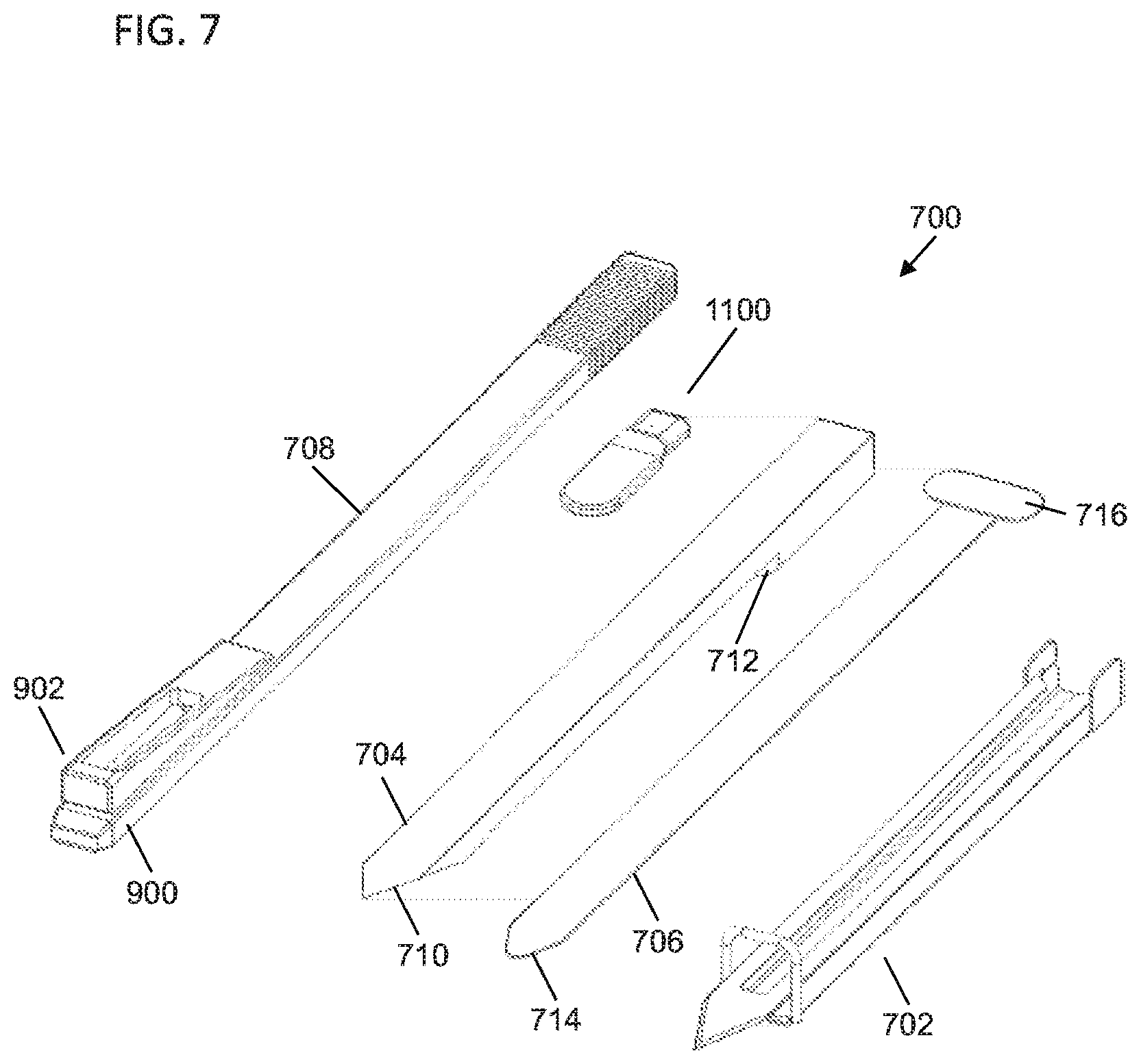
D00014

D00015

D00016

D00017

D00018

D00019

D00020

D00021

D00022
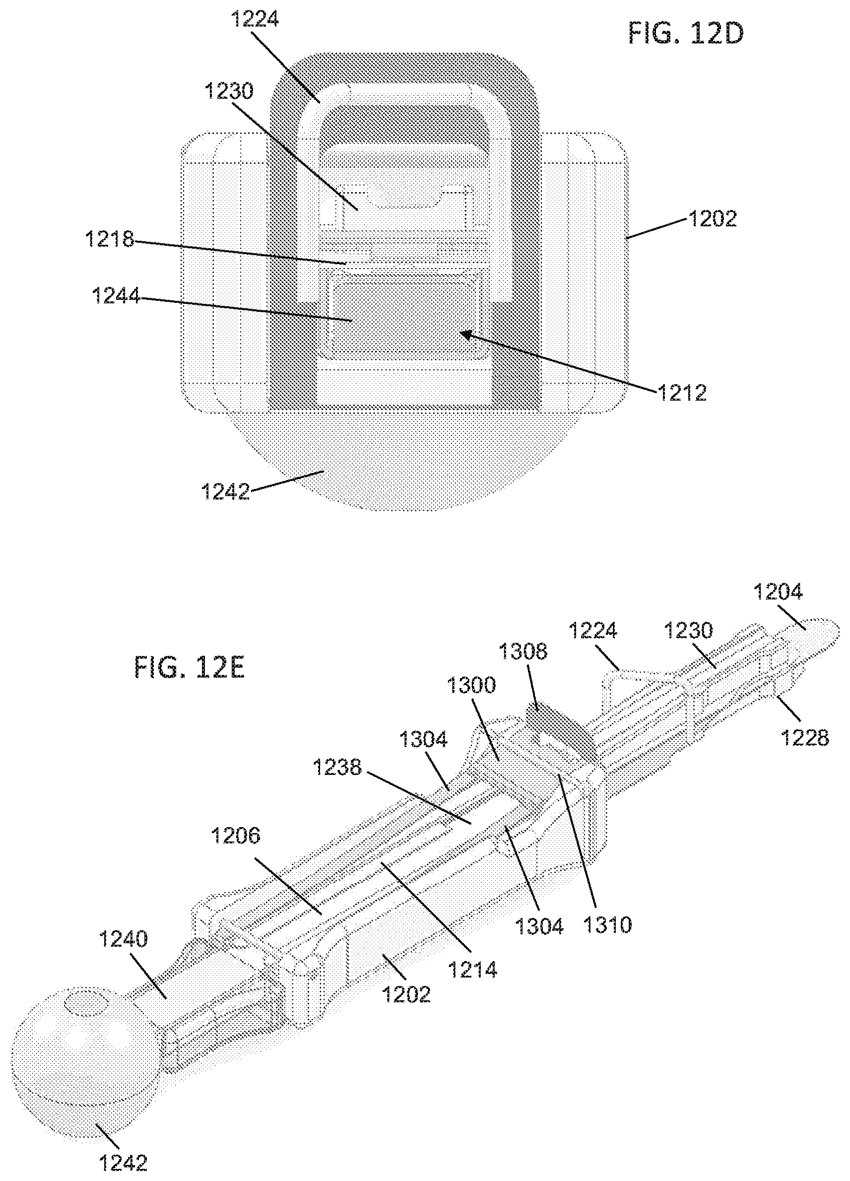
D00023

D00024

D00025
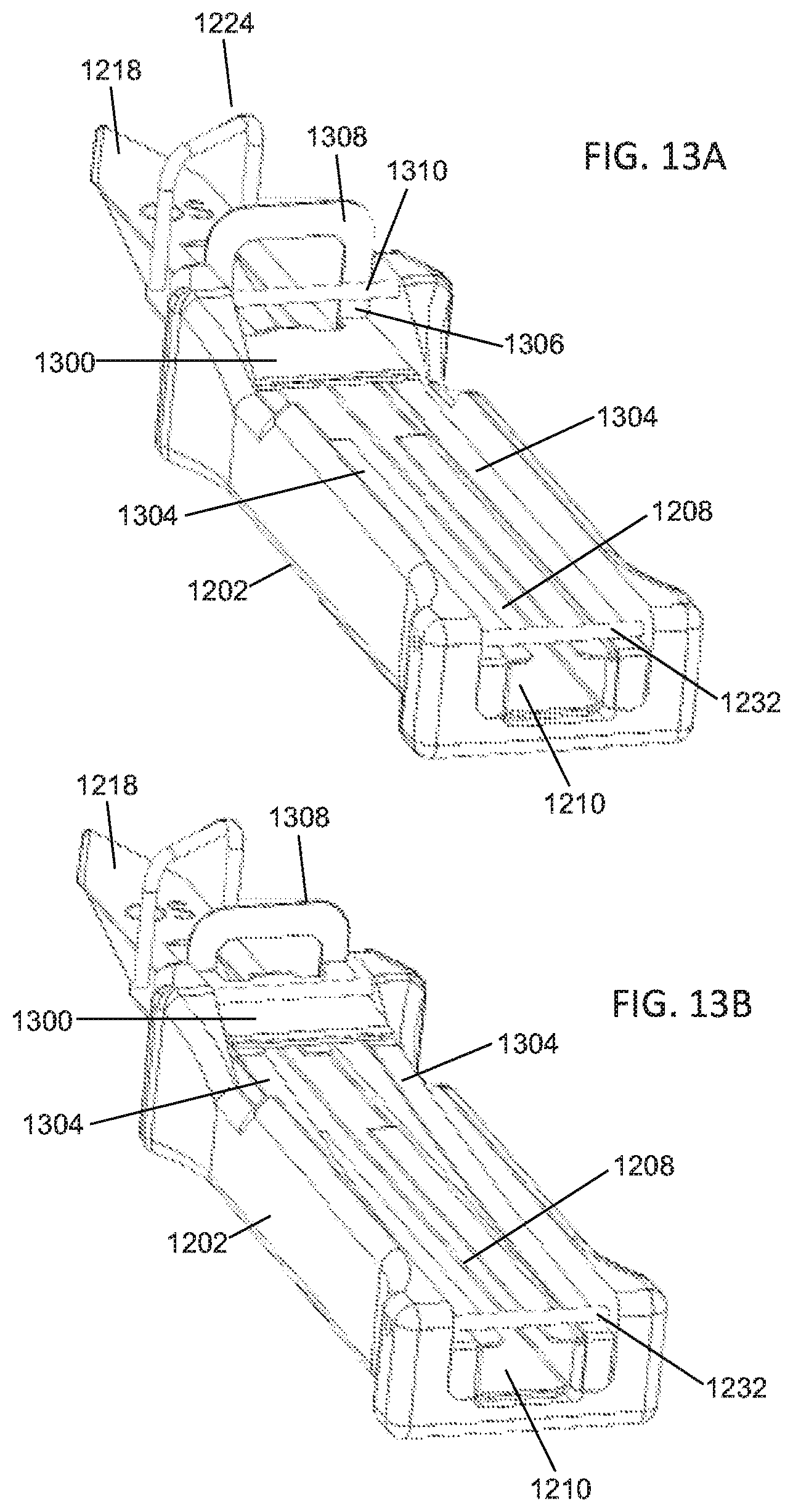
D00026

XML
uspto.report is an independent third-party trademark research tool that is not affiliated, endorsed, or sponsored by the United States Patent and Trademark Office (USPTO) or any other governmental organization. The information provided by uspto.report is based on publicly available data at the time of writing and is intended for informational purposes only.
While we strive to provide accurate and up-to-date information, we do not guarantee the accuracy, completeness, reliability, or suitability of the information displayed on this site. The use of this site is at your own risk. Any reliance you place on such information is therefore strictly at your own risk.
All official trademark data, including owner information, should be verified by visiting the official USPTO website at www.uspto.gov. This site is not intended to replace professional legal advice and should not be used as a substitute for consulting with a legal professional who is knowledgeable about trademark law.