Stent Delivery With Expansion Assisting Delivery Wire
SLAZAS; Robert ; et al.
U.S. patent application number 16/152035 was filed with the patent office on 2020-02-06 for stent delivery with expansion assisting delivery wire. This patent application is currently assigned to DePuy Synthes Products, Inc.. The applicant listed for this patent is DePuy Synthes Products, Inc.. Invention is credited to Lacey GOROCHOW, Juan LORENZO, Pedro PEDROSO, Robert SLAZAS.
| Application Number | 20200038209 16/152035 |
| Document ID | / |
| Family ID | 66333686 |
| Filed Date | 2020-02-06 |


View All Diagrams
| United States Patent Application | 20200038209 |
| Kind Code | A1 |
| SLAZAS; Robert ; et al. | February 6, 2020 |
STENT DELIVERY WITH EXPANSION ASSISTING DELIVERY WIRE
Abstract
A method for implanting a stent by providing an implantation system including a catheter, an expandable element, and a delivery wire, moving a first portion of the expandable element to exit the catheter, and maintaining a second portion of the expandable element within the catheter to establish a partially implanted configuration. Then moving the delivery wire independent of the expandable element in the partially implanted configuration, and enlarging a circumference of the expandable element in response to the moving the delivery wire.
| Inventors: | SLAZAS; Robert; (Raynham, MA) ; LORENZO; Juan; (Raynham, MA) ; GOROCHOW; Lacey; (Raynham, MA) ; PEDROSO; Pedro; (Raynham, MA) | ||||||||||
| Applicant: |
|
||||||||||
|---|---|---|---|---|---|---|---|---|---|---|---|
| Assignee: | DePuy Synthes Products,
Inc. Raynham MA |
||||||||||
| Family ID: | 66333686 | ||||||||||
| Appl. No.: | 16/152035 | ||||||||||
| Filed: | October 4, 2018 |
Related U.S. Patent Documents
| Application Number | Filing Date | Patent Number | ||
|---|---|---|---|---|
| 16056065 | Aug 6, 2018 | 10278848 | ||
| 16152035 | ||||
| Current U.S. Class: | 1/1 |
| Current CPC Class: | A61F 2002/9534 20130101; A61F 2210/0014 20130101; A61F 2/966 20130101; A61F 2002/8486 20130101; A61F 2/2436 20130101; A61F 2002/823 20130101; A61F 2002/9665 20130101; A61F 2/848 20130101; A61F 2/90 20130101; A61F 2002/9505 20130101; A61F 2/95 20130101; A61F 2/243 20130101; A61F 2250/0098 20130101 |
| International Class: | A61F 2/95 20130101 A61F002/95; A61F 2/90 20130101 A61F002/90 |
Claims
1. A method for implanting a stent comprising: providing an implantation system comprising a catheter, an expandable element, and a delivery wire; moving a first portion of the expandable element to exit the catheter; maintaining a second portion of the expandable element within the catheter to establish a partially implanted configuration; moving the delivery wire independent of the expandable element in the partially implanted configuration; and enlarging a circumference of the expandable element in response to the moving the delivery wire.
2. The method of claim 1 further comprising the steps of: positioning a proximal anchor at a proximal end of the expandable element; positioning a distal anchor at a distal end of the expandable element; positioning a distal bump on the delivery wire; positioning a proximal bump on the delivery wire proximal to the distal bump; positioning the distal bump within a lumen of the expandable element; positioning the proximal bump proximal to the expandable element; positioning the expandable element and at least a portion of the delivery wire within a lumen of the catheter; moving the distal anchor and the expandable element distally through the lumen of the catheter by pushing the delivery wire distally thereby pushing the distal bump against the distal anchor; expelling the proximal anchor from the distal end of the catheter by pushing the delivery wire distally thereby pushing the proximal bump against the proximal anchor; and expanding the expelled proximal anchor, wherein the step of moving a first portion of the expandable element to exit the catheter comprises the steps of: expelling the distal anchor from a distal end of the catheter by pushing the delivery wire distally thereby pushing the distal bump against the distal anchor; and expanding the expelled distal anchor, wherein the step of moving the delivery wire independent of the expandable element in the partially implanted configuration further comprises the step of maintaining the proximal anchor within the lumen of the catheter, and wherein the step of enlarging a circumference of the expandable element in response to the moving the delivery wire comprises the step of providing a radial force from the delivery wire against the expandable element from within the lumen of the expandable element.
3. The method of claim 1 further comprising the step of shaping a portion of the delivery wire from a substantially straight configuration to a curved configuration upon a distal movement of the portion from within the lumen of the catheter to a position outside the lumen of the catheter.
4. The method of claim 3 further comprising the step of sliding the shaped portion of the delivery wire against the expandable element from within the lumen of the expandable element.
5. The method of claim 3 further comprising the step of extending a portion of the expandable element to a wall of a vascular by moving the shaped portion against the expandable element.
6. The method of claim 1 further comprising the step of moving the second portion of the expandable element to exit the catheter and become implanted by pushing the expandable element distally with a distal movement of the delivery wire.
Description
CROSS-REFERENCE TO RELATED APPLICATIONS
[0001] This application is a divisional of U.S. application Ser. No. 16/056,065 filed on Aug. 6, 2018, the content of which is incorporated herein by reference in its entirety.
FIELD OF INVENTION
[0002] The present invention generally relates to methods for interventional therapeutic treatment or vascular surgery for treatment of defects in the vasculature, and more particularly to delivering a stent to a treatment site in a body lumen of a patient and opening the stent at the treatment site.
BACKGROUND
[0003] Stents are inserted into a blood vessel to provide an open path within the blood vessel, and they have been widely used intravascular angioplasty treatment of occluded blood vessels and other applications. Stents can be self-expanding or can be expanded by a radial force applied from inside the stent, for example when the stent is fitted with a balloon.
[0004] A braided stent can be characterized by a tube of metal wires woven together with a plain weaving technique. During delivery to a treatment site, a braided stent can travel through a catheter in an elongated, collapsed configuration, having a small diameter, and the braided stent can enlarge in diameter at a treatment site. Proper treatment with a braided stent can require that the stent extend radially to the walls of the body lumen in which the stent is implanted. Although braided stents can be self-expanding, such implants typically open with low opening forces, and therefore may not fully open to conform to a vessel wall. Post deployment, ancillary devices such as guidewires, catheters, balloons, etc. can be used to cross the braid and attempt to further expand the braided stent to improve vessel wall conformity. Issues such as unintentional braid movement or inability to fully open the braid commonly occur. Further, a braided implant that is separated from a delivery wire cannot be recovered for repositioning.
SUMMARY
[0005] It is an object of the present invention to provide systems, devices, and methods for improving vessel wall conformity of a braided stent. Generally, an expandable element having a distal anchor member at a distal end, a proximal anchor member at a proximal end, and a braided intermediate portion can be delivered to a treatment site through a catheter by a delivery wire having a first, distal bump that can be translated distally to push the distal anchor distally and release the distal anchor upon exiting a distal end of the catheter, a shaped segment that can be moved to apply a radial force from within the braided intermediate portion to expand the braided intermediate portion, and a second, proximal bump that can be translated distally to push the proximal anchor distally and expel the expandable element from the catheter.
[0006] The delivery wire can also have a third, recapture bump positioned proximal the distal bump and distal the proximal bump that can be translated proximally to push the proximal anchor proximally. A partially implanted expandable element having a distal portion expelled from the catheter and released from the delivery wire and a proximal anchor positioned within the catheter can be retracted by translating the delivery wire proximally to push the proximal anchor proximally, thereby pulling the braided portion and distal anchor proximally into the catheter.
[0007] An example vascular treatment apparatus can include a catheter, an expandable element, and a delivery wire. The catheter can have an inner lumen through which the expandable element can be delivered by the delivery wire to a treatment site. The expandable element can have a proximal end, a distal end, a braided portion located between the proximal end and the distal end, a proximal anchor member disposed at the proximal end, and a distal anchor member disposed at the distal end.
[0008] The expandable element can have a compressed configuration dimensioned to fit within the inner lumen of the catheter for delivery to the treatment site and a partially implanted configuration when the expandable element is not fully implanted at the treatment site. In the partially implanted configuration, the proximal end of the expandable element can be dimensioned to fit within the inner lumen of the catheter, and the distal end can be dimensioned larger than the catheter.
[0009] The delivery wire can be disposed within and extend through the inner lumen of the catheter and the expandable element, the expandable element having a substantially tubular shape. The delivery wire can have a proximal portion, a proximal bump member located at a distal end of the proximal portion, a distal portion, a distal bump member located at a proximal end of the distal portion, and a shapeable portion located between the proximal bump member and the distal bump. The shapeable portion can be movable from a substantially straight configuration to a curved configuration upon exiting the inner lumen of the catheter.
[0010] The expandable element can be movable from the compressed configuration to the partially implanted configuration by a distal movement of the delivery wire which can cause the distal bump member of the delivery wire to engage with the distal anchor member of the expandable element and push the distal anchor member distally. The distal anchor member can be expelled from the catheter pushing the distal anchor member out of the catheter with the distal bump member.
[0011] The delivery wire can be moved distally, proximally, and rotationally in relation to the expandable element in the partially implanted configuration, and the shapeable portion of the delivery wire can be moved to provide a radial force from within the braided portion of the expandable element when the expandable element is in the partially implanted configuration.
[0012] The shapeable portion can be movable to at least one of a symmetrical arc shape, an asymmetrical arc shape, or an approximate "S" shape in the curved configuration.
[0013] The expandable element can be in the compressed configuration and positioned entirely within the inner lumen of the catheter. When the expandable element is in the compressed configuration and positioned entirely within the inner lumen of the catheter, the shaped portion can be in the substantially straight configuration and can be positioned within a lumen of the braided portion of the expandable element, the distal bump member can be positioned within the lumen of the braided portion of the expandable element, and the proximal bump member can be positioned proximal the proximal anchor member.
[0014] The expandable element can be in the partially implanted configuration such that the distal end of the expandable element is positioned outside the catheter and the proximal end and the proximal anchor of the expandable element are positioned within the inner lumen of the catheter. When the expandable element is in the partially implanted configuration, the shapeable portion of the delivery wire can be in the curved configuration and positioned outside the catheter, and a rotation of the delivery wire in relation to the expandable element can expand a radius of the expandable element.
[0015] An example method for implanting a stent can include the steps of: providing an implantation system comprising a catheter, an expandable element, and a delivery wire; moving a first portion of the expandable element to exit the catheter; maintaining a second portion of the expandable element within the catheter to establish a partially implanted configuration; moving the delivery wire independent of the expandable element in the partially implanted configuration; and enlarging a circumference of the expandable element in response to the moving the delivery wire. The method can further include the steps of positioning a proximal anchor at a proximal end of the expandable element; positioning a distal anchor at a distal end of the expandable element; positioning a distal bump on the delivery wire; positioning a proximal bump on the delivery wire proximal to the distal bump; positioning the distal bump within a lumen of the expandable element; positioning the proximal bump proximal to the expandable element; positioning the expandable element and at least a portion of the delivery wire within a lumen of the catheter; and moving the distal anchor and the expandable element distally through the lumen of the catheter by pushing the delivery wire distally thereby pushing the distal bump against the distal anchor; expelling the proximal anchor from the distal end of the catheter by pushing the delivery wire distally thereby pushing the proximal bump against the proximal anchor; and expanding the expelled proximal anchor.
[0016] The step of moving a first portion of the expandable element to exit the catheter can include the steps of expelling the distal anchor from a distal end of the catheter by pushing the delivery wire distally thereby pushing the distal bump against the distal anchor; and expanding the expelled distal anchor.
[0017] The step of moving the delivery wire independent of the expandable element in the partially implanted configuration can include the step of maintaining the proximal anchor within the lumen of the catheter.
[0018] The step of enlarging a circumference of the expandable element in response to the moving the delivery wire can include the step of providing a radial force from the delivery wire against the expandable element from within the lumen of the expandable element.
[0019] The method can further include the steps of shaping a portion of the delivery wire from a substantially straight configuration to a curved configuration upon a distal movement of the portion from within the lumen of the catheter to a position outside the lumen of the catheter; sliding the shaped portion of the delivery wire against the expandable element from within the lumen of the expandable element; extending a portion of the expandable element to a wall of a vascular by moving the shaped portion against the expandable element; and moving the second portion of the expandable element to exit the catheter and become implanted by pushing the expandable element distally with a distal movement of the delivery wire.
[0020] An example system for implanting a stent or other such expandable element can include a catheter, a braided stent, and a delivery wire. The braided stent can be movable to a partially implanted configuration characterized by a portion of the braided stent exterior to the catheter and a portion of the braided stent within the catheter, and the delivery wire can be movable independent of the braided stent and movable to provide a force to open the braided stent when the braided stent is in a partially implanted configuration.
[0021] The braided stent can be moved in a compressed configuration through the catheter and can be movable from the compressed configuration to the partially implanted configuration. The braided stent of the system can have a first expandable anchor at a distal end and a second expandable anchor at a proximal end, such that, in the partially implanted configuration, the first expandable anchor is expanded in an implanted position distal to the catheter and the second expandable anchor is compressed within the catheter.
[0022] The delivery wire can be movable in a distal direction, a proximal direction, and in a rotational direction independent of the braided stent when the braided stent is in the partially implanted configuration. The delivery wire can extend through the braided stent when the braided stent is in the compressed configuration and when the braided stent is in the partially implanted configuration.
[0023] The delivery wire can include a pusher bump that can be positioned proximal the second expandable anchor when the braided stent is in the compressed configuration and when the braided stent is in the partially implanted configuration. The pusher bump can be movable to push the second expandable anchor distally thereby pushing the braided stent distally when the braided stent is in the partially implanted configuration.
[0024] The delivery wire can include a shapeable segment that can be positioned within the braided stent when the braided stent is in the compressed configuration and when the braided stent is in the partially implanted configuration. The shapeable segment can be movable from a substantially straight configuration when the braided stent is in the compressed configuration to a curved configuration when the braided stent is in the partially implanted configuration, and the shapeable segment can be movable independent of the braided stent when the braided stent is in the partially implanted configuration. The shapeable segment can be movable to form an arc shape, an undulating shape, or other atraumatic shape when in the curved configuration.
[0025] The delivery wire can include a puller bump positioned distal the pusher bump and the shapeable segment and also positioned proximal the first expandable anchor when the braided stent is in the compressed configuration.
BRIEF DESCRIPTION OF THE DRAWINGS
[0026] The above and further aspects of this invention are further discussed with reference to the following description in conjunction with the accompanying Figures, in which like numerals indicate like structural elements and features in various Figures. Images and drawings in the Figures are not necessarily to scale, emphasis instead being placed upon illustrating principles of the invention. As indicated, the Figures depict one or more implementations of the inventive devices, by way of example only, not by way of limitation.
[0027] FIG. 1 is a drawing depicting an implantation system in a delivery configuration according to the present invention;
[0028] FIGS. 2A to 2H are drawings illustrating steps for use of an implantation system according to the present invention;
[0029] FIGS. 3A to 3C are drawings depicting shapes of a delivery wire portion according to the present invention;
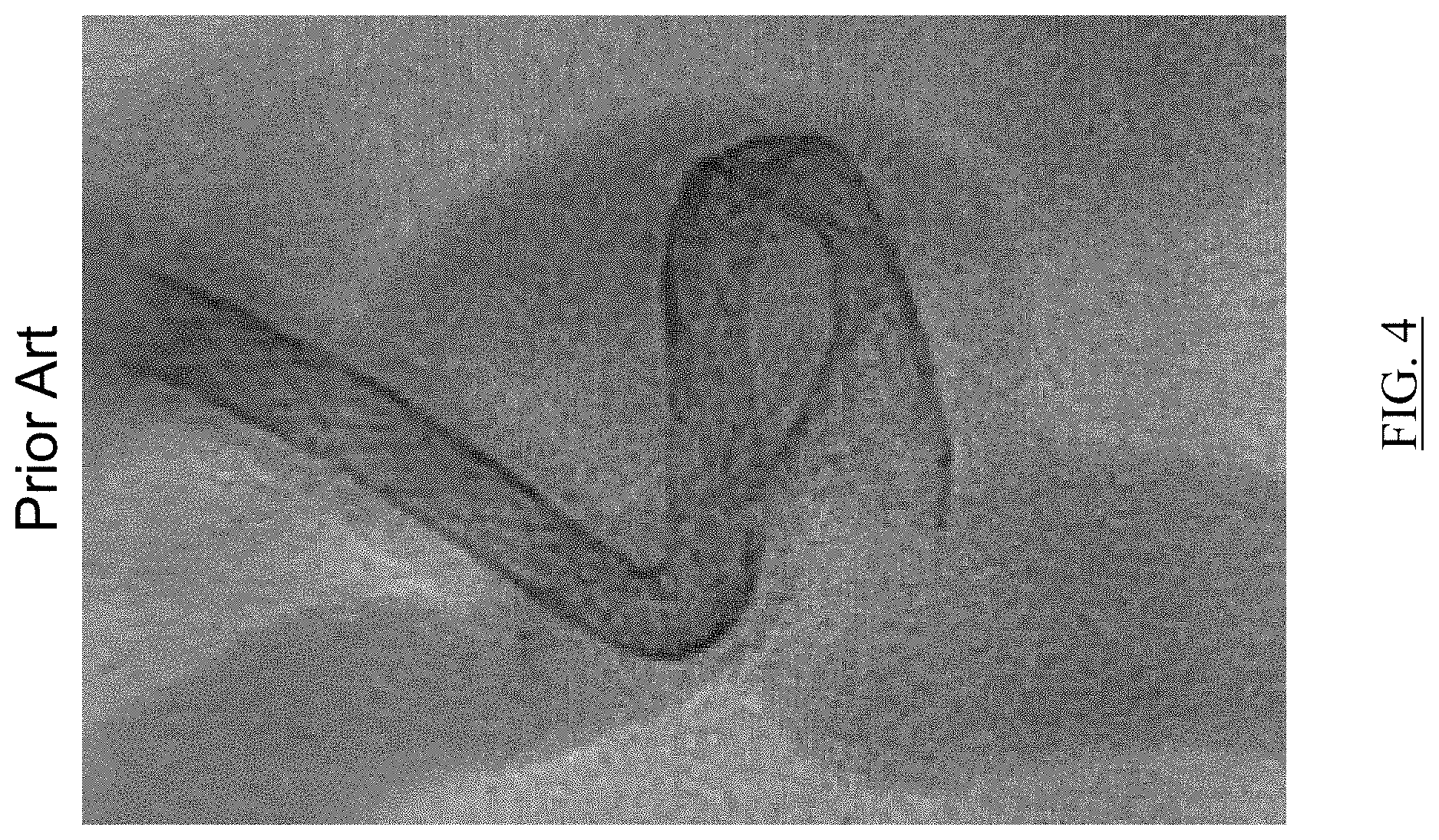
[0030] FIG. 4 is an image depicting a braided implant having a segment poorly apposed to a vessel wall as known in the art;
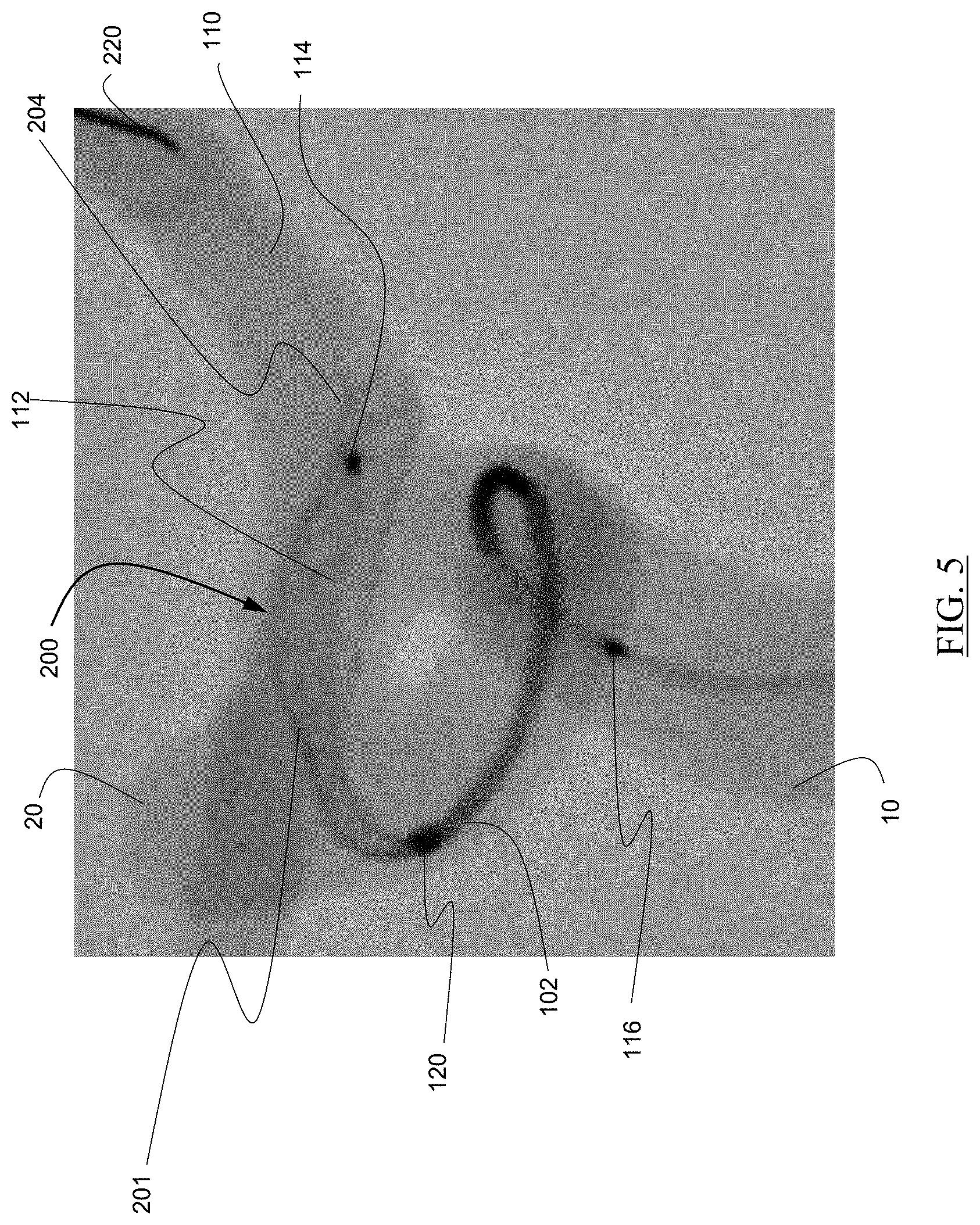
[0031] FIG. 5 is an image depicting an implantation system during implantation according to the present invention;
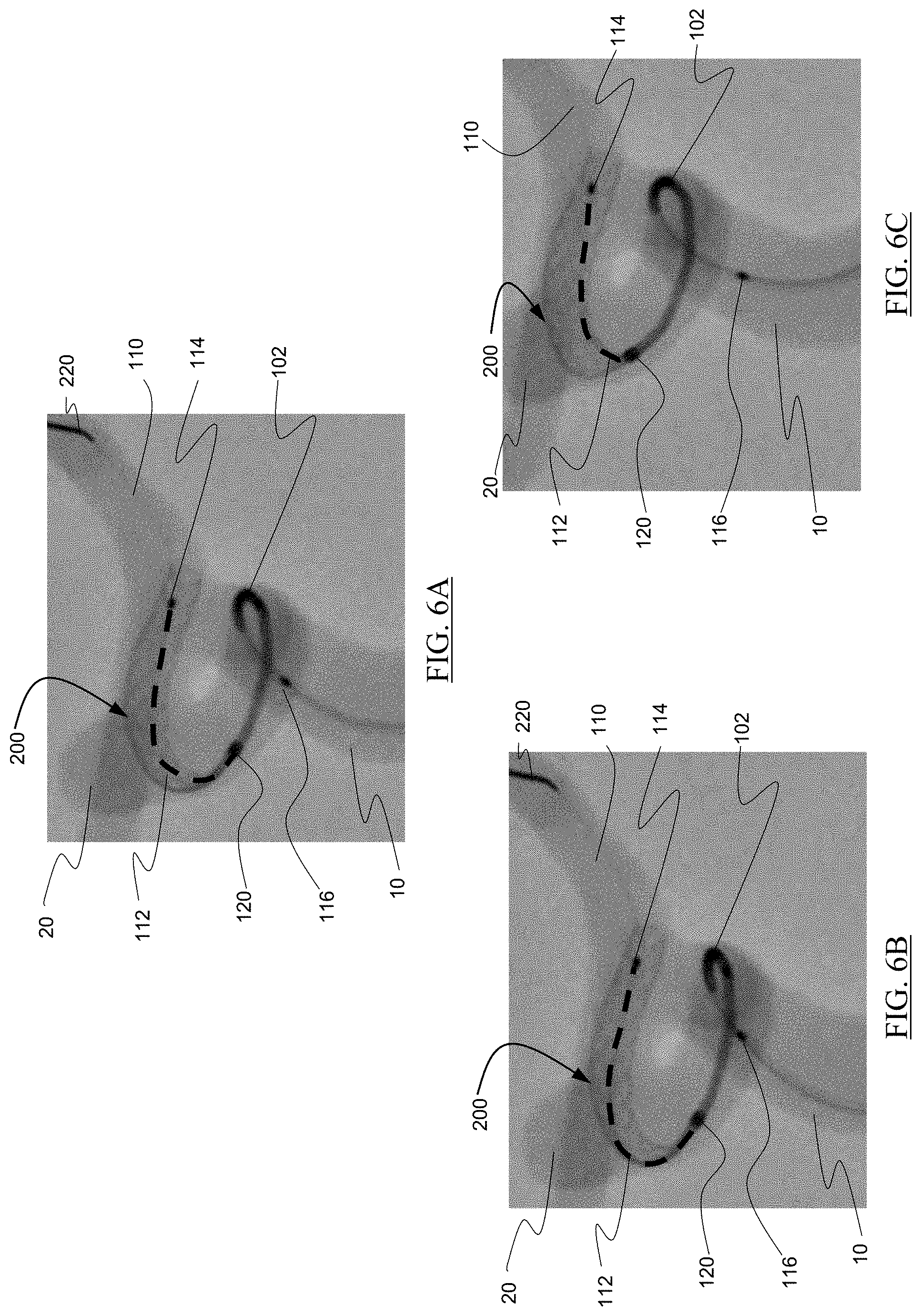
[0032] FIGS. 6A to 6C are images illustrating steps for use of an implantation system according to the present invention; and
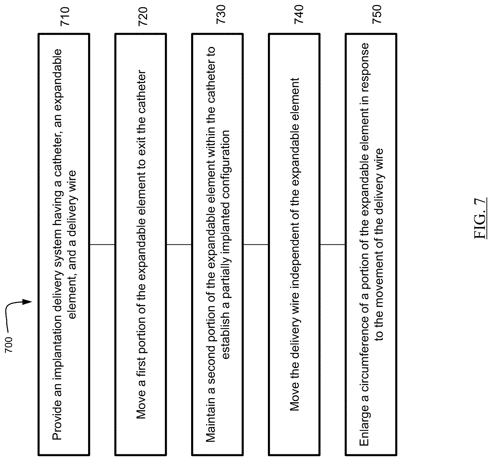
[0033] FIG. 7 is a flow diagram outlining example method steps for use of an apparatus or system for deploying an implant according to the present invention.
DETAILED DESCRIPTION
[0034] In the following detailed description, numerous specific details are set forth by way of examples in order to provide a thorough understanding of the relevant teachings. However, it should be apparent to those skilled in the art that the present teachings may be practiced without such details. In other instances, well known methods, procedures, components, and/or circuitry have been described at a relatively high-level, without detail, in order to avoid unnecessarily obscuring aspects of the present teachings.
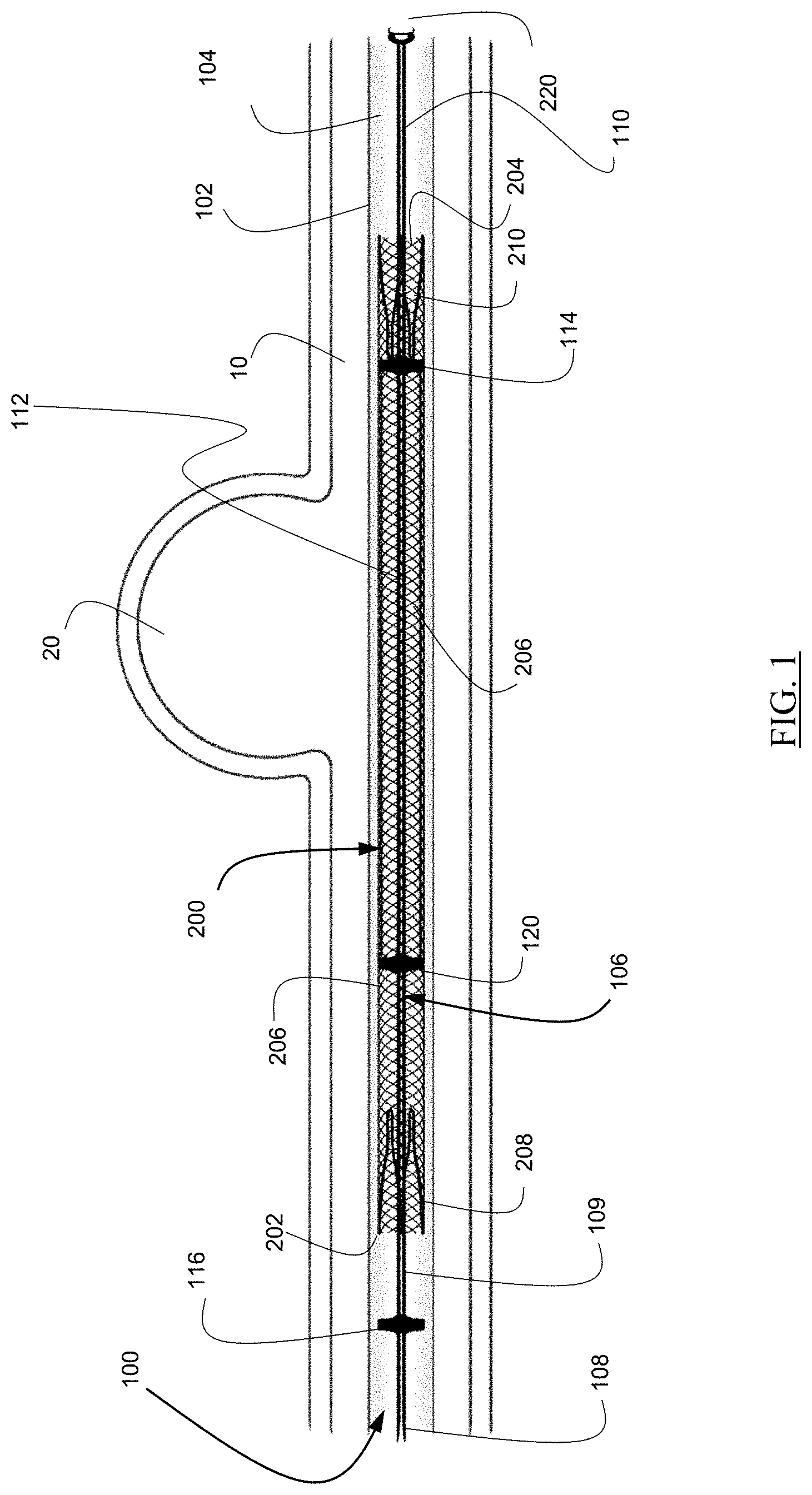
[0035] An example of an implantation system 100, as illustrated in FIG. 1 can have a catheter 102, an expandable element 200, and a delivery wire 106. The catheter 102 can have an inner lumen 104, and the expandable element 200 can be formed into a compressed configuration that is dimensioned to fit within the inner lumen 104 of the catheter 102. The expandable element 200 can have a proximal end 202, a distal end 204, a braided portion 206 located between the proximal end 202 and the distal end 204, a proximal anchor member 208 disposed at the proximal end 202, and a distal anchor member 210 disposed at the distal end 204. The delivery wire 106 can be disposed within and extend through the inner lumen 104 of the catheter 102 and the expandable element 200 and can be used to deliver the expandable element 200 to a treatment site and position the expandable element 200 at the treatment site. The delivery wire 106 can have a proximal portion 108, a distal portion 110, a proximal bump member 114 located at a distal end of the proximal portion 108, a distal bump member 114 located at a proximal end of the distal portion 110, and a shapeable portion 112 located between the proximal bump member 116 and the distal bump member 114. When the expandable element 200 is in the compressed configuration for delivery through the catheter 102, the shapeable portion 112 can have a substantially straight shape that has flexibility to navigate through a catheter 102 to a treatment site.
[0036] The delivery wire 106 can further include a recapture bump 120 positioned between the distal bump 114 and the proximal bump 116. Delivery, positioning, retraction of an expandable element such as a stent within a body lumen utilizing a delivery wire having a distal bump member, proximal bump member, and a recapture bump is the subject of another patent application filed concurrently with this application.
[0037] One or all of the bump members 114, 116, 120 can include a radiopaque material to allow the location of the bumps 144, 116, 120 to be readily visible during an implanting procedure.
[0038] The one or more anchor members 208, 210, can be projections which extend generally parallel to a longitudinal axis of the expandable element 200 and extend downward toward the longitudinal axis of the expandable element 200. The anchor members 208, 210 can serve as a radiopaque marker for improved visualization during the deployment of the expandable element 200 within the body lumen 10. The anchor members 208, 210 can be used to align the expandable element 200 so it can be pushed and pulled through the catheter 102 without damage or deformation. The anchor members 208, 210 can also be used to move the braided portion 206 into an expanded/implanted configuration. An example of the anchor member 208, 210 can be found in U.S. Ser. No. 15/299,918, the entirety of which is incorporated herein by reference.
[0039] Typically, the expandable element 200 can have a compressed configuration and an expanded, implanted, configuration. In the compressed configuration the expandable element 200 can be dimensioned to fit within the inner lumen 104 of the catheter 102. In certain examples, the catheter 102 can aid in constraining the expandable element 200 so it does not expand when contained within the catheter 102. Other elements can be used to constrain the expandable element 200 as are known in the art.
[0040] The expandable element 200 can also have a partially implanted configuration where the proximal end 202 is dimensioned to fit within the inner lumen 104 of the catheter 102 and the distal end 204 is dimensioned larger than the catheter 102.
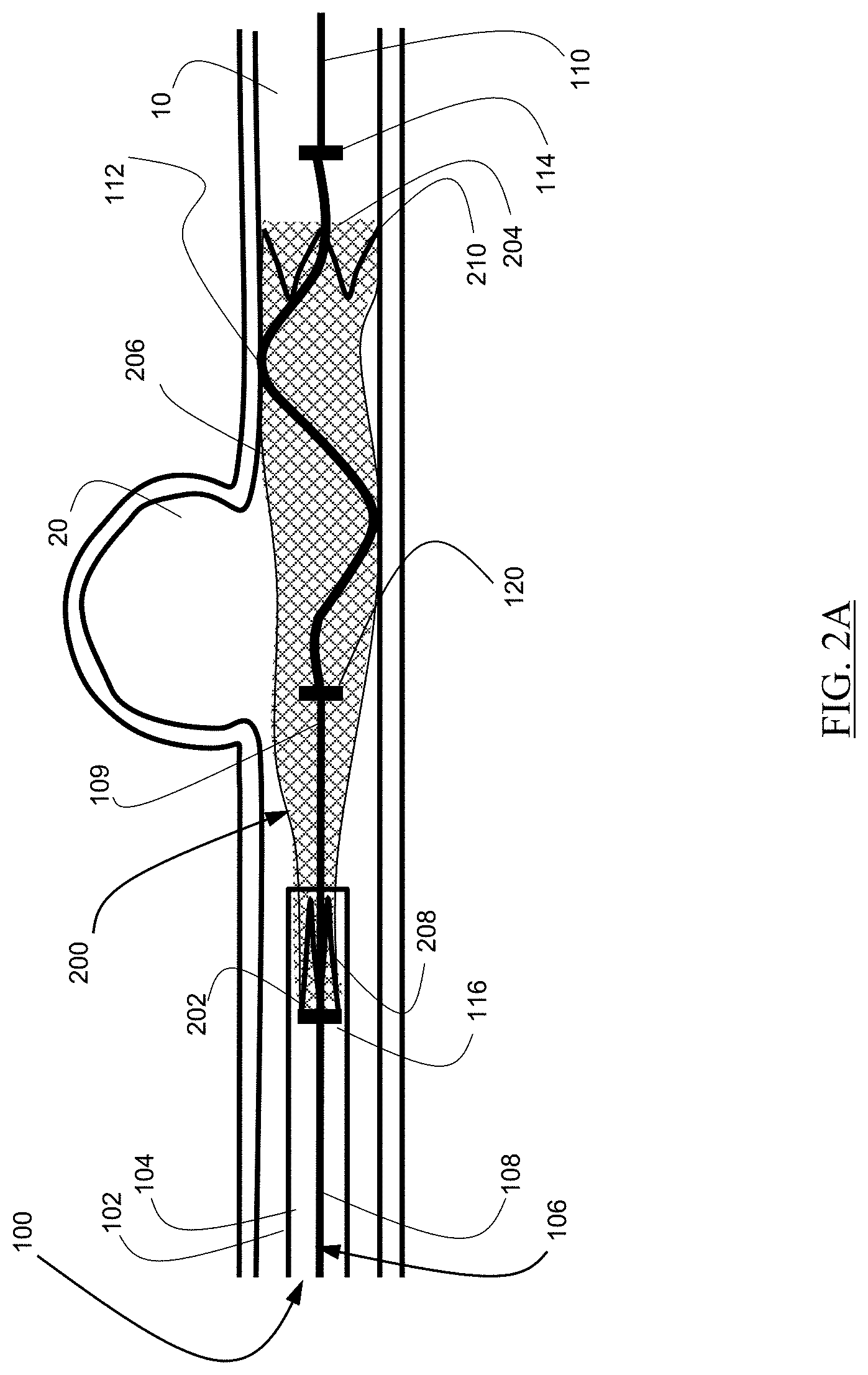
[0041] FIGS. 2A to 2H are drawings illustrating steps for use of an implantation system. When the expandable element 200 is in the collapsed configuration, the distal bump 114 can be positioned inside the expandable element 200 such that a distal movement of the delivery wire 106 can cause the distal bump 114 to push against the distal anchor 210, pulling the expandable anchor 200 through the catheter 102 to a treatment site. The distal bump member 114 can push the distal anchor member 210 to expel the distal anchor member 210 from the catheter 102, thereby moving the expandable element 200 to a partially implanted configuration as illustrated in FIG. 2A.
[0042] Upon exiting the catheter, the shapeable portion 112 of the delivery wire 106 can move from a straight shape to a curved shape as illustrated in FIGS. 2A to 2H. The shapeable portion 112 can provide a radial force from within the braided portion 206 of the expandable element 200 when the expandable element is in the partially implanted configuration.
[0043] In an example, the entire delivery wire 106, including the shapeable portion 112, can be made of stainless steel. In other examples, the delivery wire 106 and/or the shapeable portion 112 can be made of a memory shape material including a memory shape metal such as Nitinol or a polymeric memory shape material. The shapeable portion 112 can move from a substantially straight flexible configuration while in the catheter 102 to a curved configuration upon contacting bodily fluid when exiting the catheter 102. Additionally or alternatively, the shapeable portion 112 can curve to conform to the shape of a curved bodily lumen such that distal and proximal movements of the expandable element 200, delivery wire 106, and catheter 102 can cause the delivery wire 106 to move to provide a radial force from within the braided portion 206.
[0044] As illustrated in FIG. 2A, during treatment, because self-expanding braided implants may provide a low radial force during implantation, at least some of the intermediate portion 206 of the expandable element 200 may not fully conform to the walls of a body lumen 10.
[0045] As illustrated in FIG. 2B, the delivery wire 106 can be rotatable in relation to the expandable element 200, and the rotation can cause the shaped portion 112 of the delivery wire 106 to provide a force against the expandable element 200, pushing portions of the expandable element to conform to the walls of the body lumen 10.
[0046] As illustrated in FIG. 2C, the delivery wire 106 can be movable in a distal and a proximal direction in relation to the expandable element 200 without disturbing the placement of the partially implanted expandable element 200. The distal and proximal movement can also cause the shaped portion 112 of the delivery wire 106 to move against the expandable element 200, causing portions of the expandable element 200 to better conform to the walls of the body lumen 10.
[0047] As illustrated in FIG. 2D, the delivery wire 106 can be subsequently rotated to improve conformity of the expandable element 200 to the walls of the body lumen 10.
[0048] As illustrated in FIG. 2E, when the expandable element 200 is in the partially implanted configuration, the delivery wire 106 can further be moved distally to engage the proximal, pusher bump 116 with the proximal anchor 208.
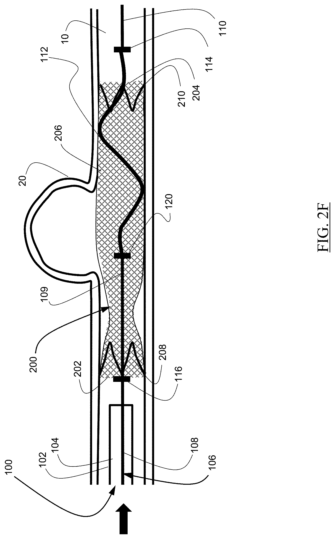
[0049] As illustrated in FIG. 2F, further distal movement of the delivery wire 106 can expel the proximal anchor 208 from the catheter 102. Once the proximal anchor 208 is expelled from the catheter 102, the proximal anchor can expand to engage the walls of the body lumen 10. Once the proximal anchor 208 is expanded, the expandable element 200 can be disengaged from the delivery wire 106. As illustrated in FIG. 2F, portions of the expandable element 200 may remain not completely conforming to the walls of the body lumen 10.
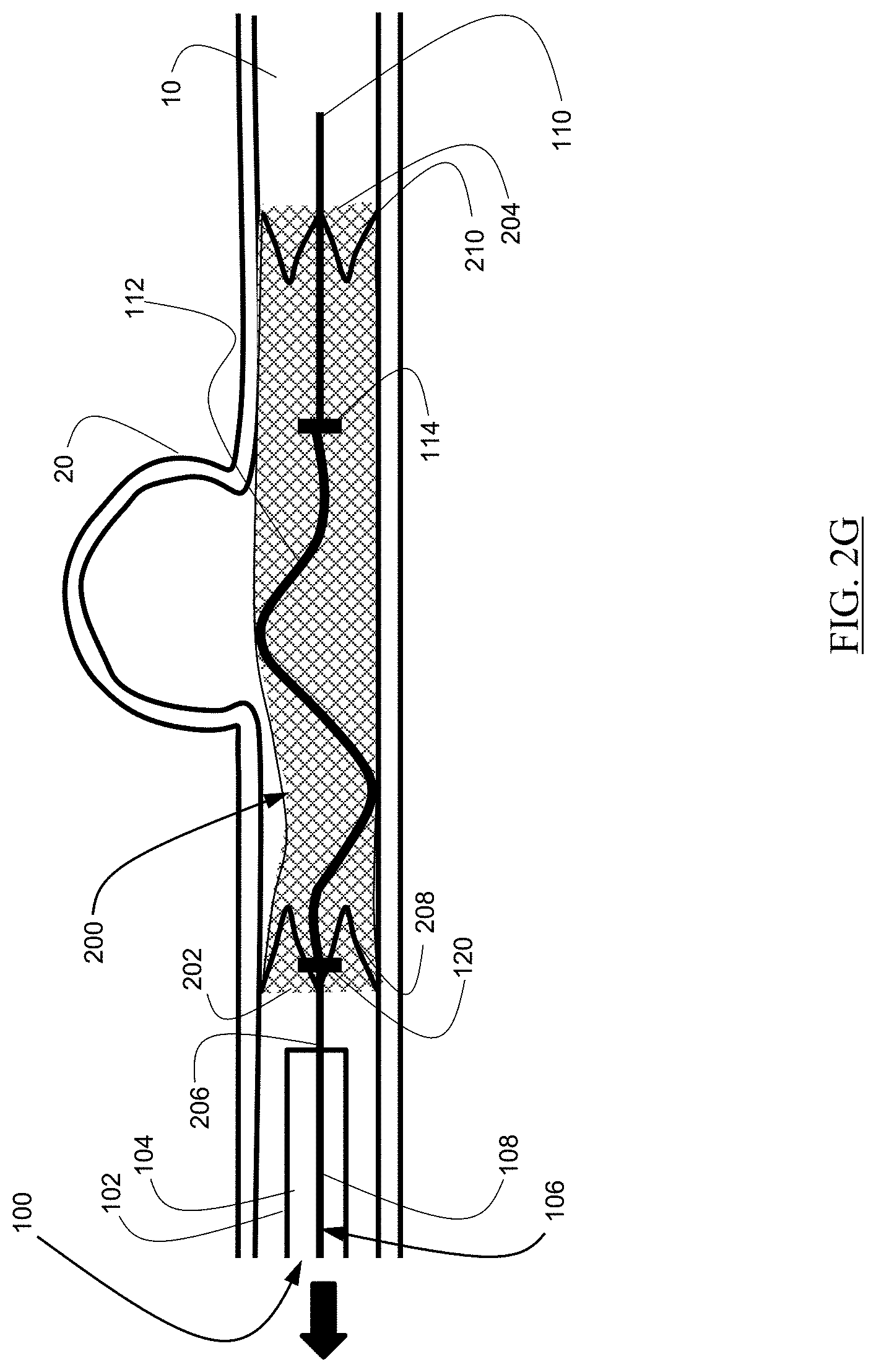
[0050] As illustrated in FIG. 2G, the delivery wire 106 can subsequently be moved proximally to side against portions of the braid, resulting in better conformity to the walls of the body lumen 10.
[0051] As illustrated in FIG. 2H, the delivery wire 106 can subsequently be rotated, and the shaped portion 112 can slide against portions of the braid, resulting in better conformity to the walls of the body lumen 10.
[0052] In the expanded configuration, as illustrated in FIG. 2H, the expandable element 200 can be expanded to conform to the dimensions of the patient's body lumen 10. The expanded dimension of the expandable element 200 allows the apparatus 100 to pass therethrough, to either advance to a second location or be withdrawn. The expandable element 200 can be expandable at least in part under its inherent proprieties, based at least on its original shape and the nature of the materials that make up the element, and further expanded by movement of the delivery wire 106 as described herein. Examples of the expandable element 200 can be one of pear shaped, ovoid, and elliptical when at its expanded diameter. The construction of the expandable element 200 is known to those of skill in the art. Other embodiments are contemplated for expandable elements 200 of this disclosure and can also be observed in U.S. Pat. Pub. 2016/0058524, a reference that is incorporated in its entirety herein.
[0053] FIGS. 3A to 3C illustrate some potential shapes that a shapeable portion 112 of the delivery wire 106 can have when the expandable element is in a partially implanted configuration. Arced, curved, "S" and "C" shaped are some examples. In one example, the shapeable portion 112 presents an atraumatic section 113 to contact both the braided implant 200 and possibly the wall of the body lumen 10. This atraumatic section 113 minimizes damage to one or both of the implant 200 and lumen 10. Another example of an atraumatic section 113 is to minimize the amount of radial force applied once the shapeable portion 112 deforms from the straight to curved shape. Too much force, even applied by an atraumatic shape 113, can still damage the implant/lumen. Too little force or shape and the implant will not open to its full potential shape.
[0054] FIG. 4 depicts a braided implant having a segment poorly apposed to a vessel wall as known in the art. It is an object of the present invention to provide devices, systems, and methods of treatment for improving conformity of an implant to a vessel wall.
[0055] FIG. 5 depicts a partially implanted expandable element that is a braided implant 200 having a distal end 204 positioned outside a catheter 102 and a delivery wire 106 positioned inside the implant 200, the delivery wire 106 having a distal coil 220 positioned distal the implant 200, a distal bump 114 positioned inside the implant, a recapture bump 120 positioned inside the implant 200 proximal the distal bump 114, and proximal bump 116 positioned proximal the implant 200 inside the catheter 102. The implant 200 as depicted in FIG. 5 has a poorly apposed portion 201 that is not extended to conform to the vasculature 10.
[0056] FIGS. 6A to 6C illustrate movement of the delivery wire 106 within the system illustrated in FIG. 5 to provide an outward radial force from within the poorly apposed portion 201 and other portions of the implant 200 not fully apposed to the walls to move those portions closer to the walls of the vascular 10. Progressing from FIGS. 6A to 6B, the delivery wire 106 can be moved distally to extend against an outer curved portion of the implant 200 and/or to provide a pushing force by the proximal bump 116 against a proximal anchor (not shown) of the implant 200. Progressing from FIGS. 6B to 6C, the delivery wire 106 can be pulled proximally to press against an inner curved portion of the implant 200 and/or to retract at least a portion of the implant 200 into the catheter 102.
[0057] In the example illustrated in FIGS. 6A to 6C, the shaped portion 112 of the delivery wire 106 can be flexible to curve to the shape of a curved vasculature 10 and need not reshape as a result of being made from a memory shape material. The shapeable portion 112 can solely curve to conform to the shape of a curved bodily lumen such that distal and proximal movements of the expandable element 200, delivery wire 106, and catheter 102 can cause the delivery wire to move to provide a radial force from within the braided portion 206. In this example, the non-preshaped shapeable portion 112 can curve based on bringing the deliver wire 106 through the inside of the curve and the outside of a curve of a vasculature where the braided portion 206 is to be implanted.
[0058] FIG. 7 is a flow diagram outlining example method steps for use of an apparatus or system for deploying an implant. The method steps can be implemented by an of the example means described herein or by any means that would be known to one of ordinary skill in the art.
[0059] Referring to method 700 illustrated in FIG. 7, in step 710 an implantation delivery system having a catheter, an expandable element, and a delivery wire can be provided. The implantation delivery system can be any of the delivery systems described herein having any combination of the features described here, as well as any features that would be known to one skilled in the art. In step 720 a first portion of the expandable element can be moved to exit the catheter. In step 730 a second portion of the expandable element can be maintained within the catheter to establish a partially implanted configuration. In step 740 the delivery wire can be moved independent of the expandable element in the partially implanted configuration. In step 750 a circumference of the expandable element can be enlarged in response to the movement of the delivery wire in step 740.
[0060] The descriptions contained herein are examples of embodiments of the invention and are not intended in any way to limit the scope of the invention. As described herein, the invention contemplates many variations and modifications of the implantation system and methods of use thereof, including various shapes of the shapeable portion of the delivery wire, various materials, various treatments, and various stent geometries. These modifications would be apparent to those having ordinary skill in the art to which this invention relates and are intended to be within the scope of the claims which follow.
* * * * *
D00000
D00001
D00002
D00003
D00004
D00005
D00006
D00007
D00008
D00009
D00010
D00011
D00012
D00013
D00014
XML
uspto.report is an independent third-party trademark research tool that is not affiliated, endorsed, or sponsored by the United States Patent and Trademark Office (USPTO) or any other governmental organization. The information provided by uspto.report is based on publicly available data at the time of writing and is intended for informational purposes only.
While we strive to provide accurate and up-to-date information, we do not guarantee the accuracy, completeness, reliability, or suitability of the information displayed on this site. The use of this site is at your own risk. Any reliance you place on such information is therefore strictly at your own risk.
All official trademark data, including owner information, should be verified by visiting the official USPTO website at www.uspto.gov. This site is not intended to replace professional legal advice and should not be used as a substitute for consulting with a legal professional who is knowledgeable about trademark law.