Spinal Surgery Systems And Methods
KAPITAN; John ; et al.
U.S. patent application number 16/435128 was filed with the patent office on 2020-02-06 for spinal surgery systems and methods. This patent application is currently assigned to GetSet Surgical SA. The applicant listed for this patent is GetSet Surgical SA. Invention is credited to Lawrence BINDER, John KAPITAN, Ole STOKLUND.
| Application Number | 20200038201 16/435128 |
| Document ID | / |
| Family ID | 69228116 |
| Filed Date | 2020-02-06 |


View All Diagrams
| United States Patent Application | 20200038201 |
| Kind Code | A1 |
| KAPITAN; John ; et al. | February 6, 2020 |
SPINAL SURGERY SYSTEMS AND METHODS
Abstract
An intervertebral spacer may include a superior surface configured to engage a superior vertebral body, an inferior surface configured to engage an inferior vertebral body, and a peripheral wall extending from the superior surface to the inferior surface. A proximal end of the peripheral wall may include with a cam surface that is rotatable against a complementary cam surface of an inserter tool such that a first force causes the intervertebral spacer to pivot, relative to the inserter tool, about a pivot point associated with the cam surface.
| Inventors: | KAPITAN; John; (Leicester, NC) ; STOKLUND; Ole; (Lausanne, CH) ; BINDER; Lawrence; (Miami, FL) | ||||||||||
| Applicant: |
|
||||||||||
|---|---|---|---|---|---|---|---|---|---|---|---|
| Assignee: | GetSet Surgical SA Epalinges CH |
||||||||||
| Family ID: | 69228116 | ||||||||||
| Appl. No.: | 16/435128 | ||||||||||
| Filed: | June 7, 2019 |
Related U.S. Patent Documents
| Application Number | Filing Date | Patent Number | ||
|---|---|---|---|---|
| 62712938 | Jul 31, 2018 | |||
| Current U.S. Class: | 1/1 |
| Current CPC Class: | A61F 2002/4628 20130101; A61B 17/8875 20130101; A61B 17/8685 20130101; A61F 2002/4627 20130101; A61B 2017/564 20130101; A61F 2/4603 20130101; A61B 17/888 20130101; A61F 2002/4615 20130101; A61B 17/7032 20130101; A61F 2/442 20130101; A61F 2/4611 20130101; A61B 17/7082 20130101; A61F 2250/0006 20130101; A61F 2/447 20130101; A61B 17/8615 20130101; A61B 17/8888 20130101; A61F 2002/30593 20130101; A61B 17/7037 20130101; A61F 2002/30261 20130101; A61F 2002/30112 20130101 |
| International Class: | A61F 2/46 20060101 A61F002/46; A61F 2/44 20060101 A61F002/44 |
Claims
1. An intervertebral spacer comprising: a superior surface configured to engage a superior vertebral body; an inferior surface configured to engage an inferior vertebral body; and a peripheral wall extending from the superior surface to the inferior surface, the peripheral wall comprising: a distal end; and a proximal end comprising a cam surface that is rotatable against a complementary cam lobe surface of an inserter tool such that a first force causes the intervertebral spacer to pivot, relative to the inserter tool, about a pivot point associated with the cam surface.
2. The intervertebral spacer of claim 1, wherein the cam surface comprises a concave surface having a first radius of curvature, the concave surface configured to receive a cam lobe comprising a complementarily shaped convex surface having a second radius of curvature that is substantially equal to the first radius of curvature.
3. The intervertebral spacer of claim 1, wherein the cam surface comprises a convex surface having a first radius of curvature, the convex surface configured to receive a cam lobe comprising a complementarily shaped concave surface having a second radius of curvature that is substantially equal to the first radius of curvature.
4. The intervertebral spacer of claim 1 further comprising: an aperture formed in the proximal end of the intervertebral spacer; and a chamfered surface proximate the aperture, wherein the chamfered surface is configured to receive a second force from an inserter shaft tip to aid the first force in pivoting the intervertebral spacer about the pivot point associated with the cam surface.
5. The intervertebral spacer of claim 1, wherein the peripheral wall further comprises: a first side extending from the proximal end to the distal end; and a second side extending from the proximal end to the distal end, wherein the cam surface is located closer to the first side of the intervertebral spacer than the second side of the intervertebral spacer.
6. The intervertebral spacer of claim 5, wherein: the superior surface of the intervertebral spacer comprises a third radius of curvature extending from the proximal end of the intervertebral spacer to the distal end of the intervertebral spacer; and the inferior surface of the intervertebral spacer comprises a fourth radius of curvature extending from the proximal end of the intervertebral spacer to the distal end of the intervertebral spacer that is substantially equal to the third radius of curvature.
7. The intervertebral spacer of claim 5, wherein: the superior surface of the intervertebral spacer comprises a fifth radius of curvature extending from the first side of the intervertebral spacer to the second side of the intervertebral spacer; and the inferior surface of the intervertebral spacer comprises a sixth radius of curvature extending from the first side of the intervertebral spacer to the second side of the intervertebral spacer that is substantially equal to the fifth radius of curvature.
8. A spinal fusion system comprising: an intervertebral spacer comprising: a superior surface configured to engage a superior vertebral body; an inferior surface configured to engage an inferior vertebral body; and a peripheral wall extending from the superior surface to the inferior surface, the peripheral wall comprising: a distal end; and a proximal end comprising a cam surface that is rotatable against a complementary cam lobe surface such that a first force causes the intervertebral spacer to pivot about a pivot point associated with the cam surface; and an inserter tool comprising: a shroud having a proximal end and a distal end; a handle located toward the proximal end of the shroud; and a cam lobe located at the distal end of the shroud, the shroud extending between the handle and the cam lobe, wherein the cam lobe is configured to impart the first force to the cam surface that causes the intervertebral spacer to pivot about the pivot point associated with the cam surface.
9. The spinal fusion system of claim 8, wherein: the inserter tool further comprises an inserter shaft, the inserter shaft comprising: a proximal end; a distal end; and an inserter shaft tip located at the distal end of the inserter shaft; and the intervertebral spacer further comprises: an aperture formed in the proximal end of the intervertebral spacer; and a chamfered surface proximate the aperture, wherein the chamfered surface is configured to receive a second force from the inserter shaft tip to aid the first force in pivoting the intervertebral spacer about the pivot point associated with the cam surface.
10. The spinal fusion system of claim 9, wherein: the inserter shaft further comprises: a knob located at the proximal end of the inserter shaft; and first threading formed along the inserter shaft proximate the inserter shaft tip; and the intervertebral spacer further comprises: second threading formed within the aperture, wherein the inserter shaft is configured to translate proximally and distally relative to the shroud, and wherein the inserter shaft is removably couplable to the intervertebral spacer by rotating the inserter shaft relative to the intervertebral spacer to engage the first threading with the second threading.
11. The spinal fusion system of claim 8, wherein: the cam surface comprises a concave surface having a first radius of curvature; and the cam lobe comprises a complementarily shaped convex surface having a second radius of curvature that is substantially equal to the first radius of curvature.
12. The spinal fusion system of claim 8, wherein: the cam surface comprises a convex surface having a first radius of curvature; and the cam lobe comprises a complementarily shaped concave surface having a second radius of curvature that is substantially equal to the first radius of curvature.
13. The spinal fusion system of claim 8, wherein the peripheral wall further comprises: a first side extending from the proximal end to the distal end; and a second side extending from the proximal end to the distal end; wherein the cam surface is located closer to the first side of the intervertebral spacer than the second side of the intervertebral spacer.
14. The spinal fusion system of claim 13, wherein: the superior surface of the intervertebral spacer comprises a third radius of curvature extending from the proximal end of the intervertebral spacer to the distal end of the intervertebral spacer; and the inferior surface of the intervertebral spacer comprises a fourth radius of curvature extending from the proximal end of the intervertebral spacer to the distal end of the intervertebral spacer that is substantially equal to the third radius of curvature.
15. The spinal fusion system of claim 13, wherein: the superior surface of the intervertebral spacer comprises a fifth radius of curvature extending from the first side of the intervertebral spacer to the second side of the intervertebral spacer; and the inferior surface of the intervertebral spacer comprises a sixth radius of curvature extending from the first side of the intervertebral spacer to the second side of the intervertebral spacer that is substantially equal to the fifth radius of curvature.
16. A method of inserting an intervertebral spacer comprising a cam surface between two vertebral bodies of a patient through use of an inserter tool that comprises a complimentarily shaped cam lobe configured to engage the cam surface and permit selective rotation of the intervertebral spacer relative to the inserter tool, the method comprising: aligning the cam surface of the intervertebral spacer with the complimentarily shaped cam lobe of the inserter tool; moving the cam surface into engagement with the complimentarily shaped cam lobe; and inserting the intervertebral spacer between the two vertebral bodies of the patient.
17. The method of claim 16, wherein the inserter tool comprises an inserter shaft with first threading and the intervertebral spacer comprises an aperture with second threading, further comprising: engaging the first threading of the inserter shaft with the second threading of the intervertebral spacer to removably couple the intervertebral spacer to the inserter shaft.
18. The method of claim 17 further comprising: disengaging the first threading of the inserter shaft with the second threading of the intervertebral spacer; and removing the inserter shaft from the patient.
19. The method of claim 18 further comprising: applying a first force to the cam surface with the complimentarily shaped cam lobe to cause the intervertebral spacer to pivot, relative to the inserter tool, about a pivot point associated with the cam surface.
20. The method of claim 19, wherein the inserter shaft comprises an inserter shaft tip and the intervertebral spacer comprises a chamfered surface proximate the aperture, further comprising: applying a second force to the chamfered surface with the inserter shaft tip to aid the first force in pivoting the intervertebral spacer about the pivot point associated with the cam surface.
Description
CROSS-REFERENCE TO RELATED APPLICATIONS
[0001] This application claims the benefit of U.S. Provisional Patent Application Ser. No. 62/712,938 filed on Jul. 31, 2018, entitled "SPINAL SURGERY SYSTEMS AND METHODS," the disclosure of which is incorporated herein by reference in its entirety.
TECHNICAL FIELD
[0002] The present disclosure relates to surgical systems, methods, instruments, and devices. More specifically, the present disclosure relates to improved surgical systems, methods, devices, and instruments for implanting intervertebral spacers between adjacent vertebral bodies in a patient.
BACKGROUND
[0003] Spinal fixation procedures utilizing intervertebral spacers can be used to correct spinal conditions such as degenerative disc disease, spondylolisthesis, spinal deformities, or other spinal conditions through minimally invasive or invasive spinal surgery. For example, intervertebral discs can degenerate or otherwise become damaged over time. In some instances, an intervertebral spacer can be positioned within a space previously occupied by a disc between adjacent vertebral bodies. Such intervertebral spacers can help maintain a desired spacing between adjacent vertebrae and/or promote fusion between adjacent vertebrae. The use of bone graft and/or other materials within an intervertebral spacer can also facilitate the fusion of adjacent vertebral bodies. Accordingly, a need exists for improved intervertebral spacers and related surgical instrumentation, tools, systems and methods.
SUMMARY
[0004] The various systems and methods of the present disclosure have been developed in response to the present state of the art, and in particular, in response to the problems and needs in the art that have not yet been fully solved by currently available surgical devices, instruments, systems, and methods for implanting intervertebral spacers between vertebral bodies of a patient.
[0005] According to some embodiments, an intervertebral spacer may include a superior surface configured to engage a superior vertebral body, an inferior surface configured to engage an inferior vertebral body, and a peripheral wall extending from the superior surface to the inferior surface. The peripheral wall may have a distal end and a proximal end that includes a cam surface that is rotatable against a complementary cam surface of an inserter tool such that a first force causes the intervertebral spacer to pivot, relative to the inserter tool, about a pivot point associated with the cam surface.
[0006] In other embodiments, a spinal fusion system may include an intervertebral spacer and an inserter tool. The intervertebral spacer may include a superior surface configured to engage a superior vertebral body, an inferior surface configured to engage an inferior vertebral body, and a peripheral wall extending from the superior surface to the inferior surface. The peripheral wall may have a distal end and a proximal end comprising a cam surface that is rotatable against a complementary cam surface such that a first force causes the intervertebral spacer to pivot about a pivot point associated with the cam surface. The inserter tool may include a shroud having a proximal end and a distal end, a handle located toward the proximal end of the shroud, and a cam lobe located at the distal end of the shroud, with the shroud extending between the handle and the cam lobe. The cam lobe may be configured to impart the first force to the cam surface that causes the intervertebral spacer to pivot about the pivot point associated with the cam surface.
[0007] In yet other embodiments, a method for inserting an intervertebral spacer comprising a cam surface between two vertebral bodies of a patient through use of an inserter tool that comprises a complimentarily shaped cam lobe configured to engage the cam surface and permit selective rotation of the intervertebral spacer relative to the inserter tool may include aligning the cam surface of the intervertebral spacer with the complimentarily shaped cam lobe of the inserter tool. The method may also include moving the cam surface into engagement with the complimentarily shaped cam lobe and inserting the intervertebral spacer between the two vertebral bodies of the patient.
[0008] These and other features and advantages of the present disclosure will become more fully apparent from the following description and appended claims, or may be learned by the practice of the systems and methods set forth hereinafter.
BRIEF DESCRIPTION OF THE DRAWINGS
[0009] Exemplary embodiments of the disclosure will become more fully apparent from the following description and appended claims, taken in conjunction with the accompanying drawings. Understanding that these drawings depict only exemplary embodiments and are, therefore, not to be considered limiting of the scope of the appended claims, the exemplary embodiments of the present disclosure will be described with additional specificity and detail through use of the accompanying drawings in which:
[0010] FIG. 1A is a perspective top view of a proximal end of an intervertebral spacer 100, according to an embodiment of the present disclosure;
[0011] FIG. 1B is a perspective top view of a distal end of the intervertebral spacer 100 of FIG. 1A;
[0012] FIG. 1C is a top view of the intervertebral spacer 100 of FIG. 1A;
[0013] FIG. 1D is a bottom view of the intervertebral spacer 100 of FIG. 1A;
[0014] FIG. 1E illustrates a first side of the intervertebral spacer 100 of FIG. 1A;
[0015] FIG. 1F illustrates a second side of the intervertebral spacer 100 of FIG. 1A;
[0016] FIG. 1G is a perspective view of the distal end of the intervertebral spacer 100 of FIG. 1A;
[0017] FIG. 1H is a perspective view of the proximal end of the intervertebral spacer 100 of FIG. 1A;
[0018] FIG. 2A is a perspective view of a first radiopaque marker 200, according to an embodiment of the present disclosure;
[0019] FIG. 2B is a side view of the first radiopaque marker 200 of FIG. 2A;
[0020] FIG. 3A is a perspective view of a second radiopaque marker 300, according to an embodiment of the present disclosure;
[0021] FIG. 3B is a side view of the second radiopaque marker 300 of FIG. 3A;
[0022] FIG. 4 is an exploded view of the intervertebral spacer 100 of FIG. 1A and the first and second radiopaque markers 200, 300 of FIGS. 2A-3B prior to assembly;
[0023] FIG. 5A is a perspective top view of a proximal end of an intervertebral spacer 500, according to an embodiment of the present disclosure;
[0024] FIG. 5B is a perspective top view of a distal end of the intervertebral spacer 500 of FIG. 5A;
[0025] FIG. 5C is a top view of the intervertebral spacer 500 of FIG. 5A;
[0026] FIG. 5D is a bottom view of the intervertebral spacer 500 of FIG. 5A;
[0027] FIG. 5E illustrates a first side of the intervertebral spacer 500 of FIG. 5A;
[0028] FIG. 5F illustrates a second side of the intervertebral spacer 500 of FIG. 5A;
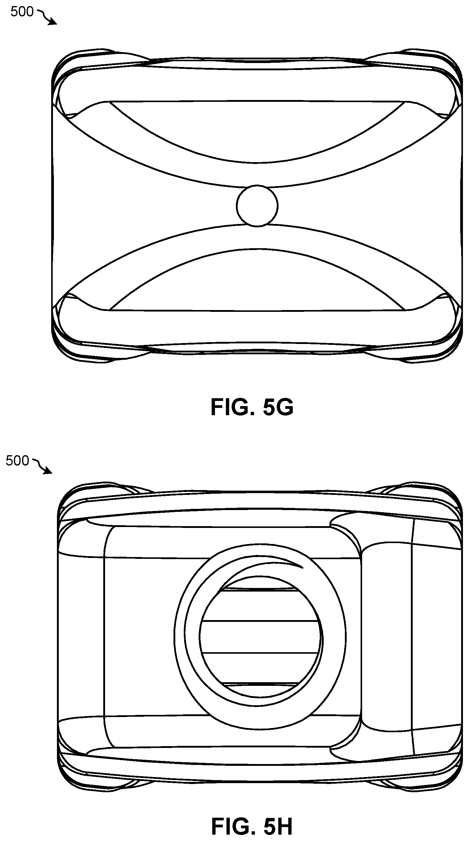
[0029] FIG. 5G illustrates the distal end of the intervertebral spacer 500 of FIG. 5A;
[0030] FIG. 5H illustrates the proximal end of the intervertebral spacer 500 of FIG. 5A;
[0031] FIG. 6A is a perspective top view of a proximal end of an intervertebral spacer 600, according to an embodiment of the present disclosure;
[0032] FIG. 6B is a perspective top view of a distal end of the intervertebral spacer 600 of FIG. 6A;
[0033] FIG. 6C is a top view of the intervertebral spacer 600 of FIG. 6A;
[0034] FIG. 6D is a bottom view of the intervertebral spacer 600 of FIG. 6A;
[0035] FIG. 6E illustrates a first side of the intervertebral spacer 600 of FIG. 6A;
[0036] FIG. 6F illustrates a second side of the intervertebral spacer 600 of FIG. 6A;
[0037] FIG. 6G illustrates the distal end of the intervertebral spacer 600 of FIG. 6A;
[0038] FIG. 6H illustrates the proximal end of the intervertebral spacer 600 of FIG. 6A;
[0039] FIG. 7A is a perspective top view of a proximal end of an intervertebral spacer 700, according to an embodiment of the present disclosure;
[0040] FIG. 7B is a perspective top view of a distal end of the intervertebral spacer 700 of FIG. 7A;
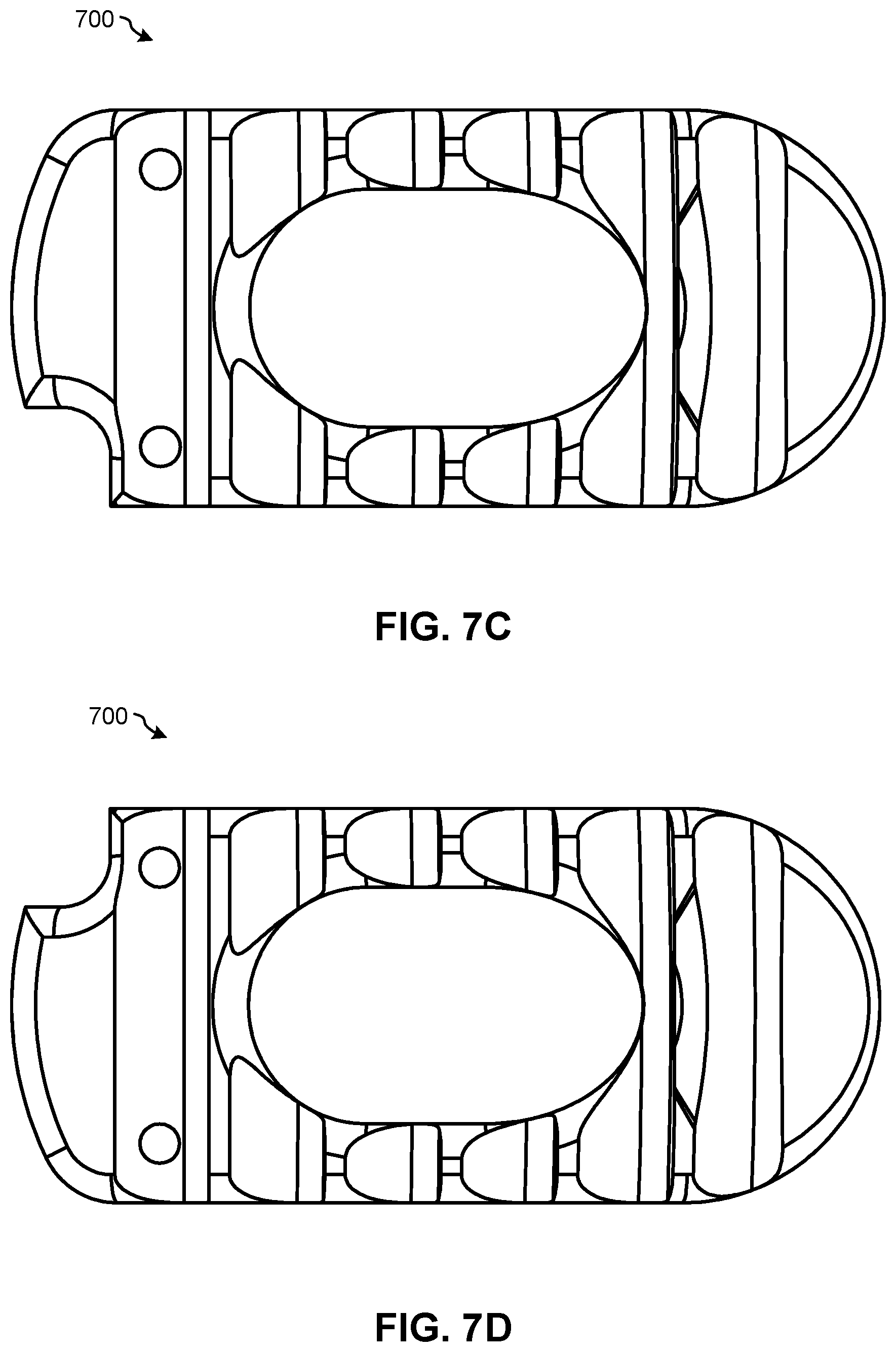
[0041] FIG. 7C is a top view of the intervertebral spacer 700 of FIG. 7A;
[0042] FIG. 7D is a bottom view of the intervertebral spacer 700 of FIG. 7A;
[0043] FIG. 7E illustrates a first side of the intervertebral spacer 700 of FIG. 7A;
[0044] FIG. 7F illustrates a second side of the intervertebral spacer 700 of FIG. 7A;
[0045] FIG. 7G illustrates the distal end of the intervertebral spacer 700 of FIG. 7A;
[0046] FIG. 7H illustrates the proximal end of the intervertebral spacer 700 of FIG. 7A;
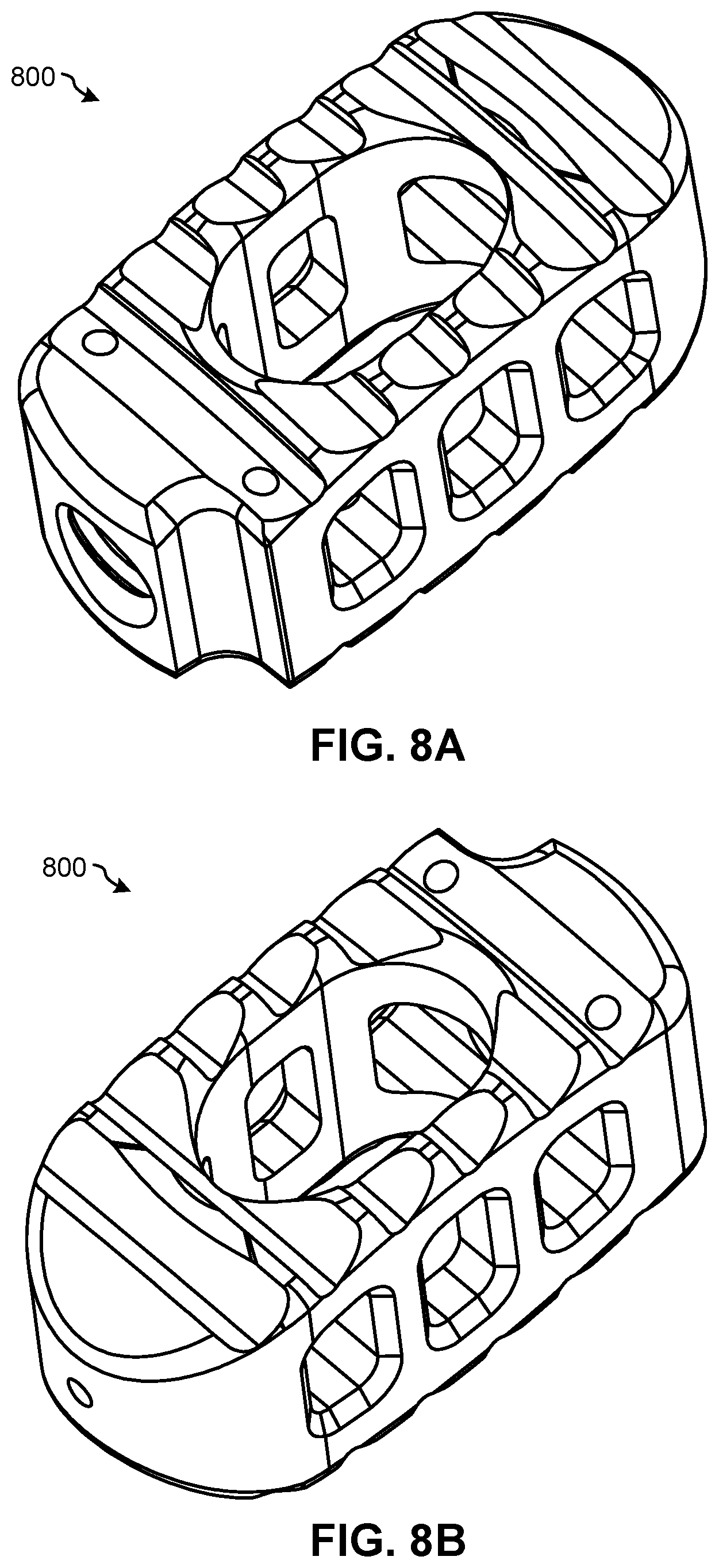
[0047] FIG. 8A is a perspective top view of a proximal end of an intervertebral spacer 800, according to an embodiment of the present disclosure;
[0048] FIG. 8B is a perspective top view of a distal end of the intervertebral spacer 800 of FIG. 8A;
[0049] FIG. 8C is a top view of the intervertebral spacer 800 of FIG. 8A;
[0050] FIG. 8D is a bottom view of the intervertebral spacer 800 of FIG. 8A;
[0051] FIG. 8E illustrates a first side of the intervertebral spacer 800 of FIG. 8A;
[0052] FIG. 8F illustrates a second side of the intervertebral spacer 800 of FIG. 8A;
[0053] FIG. 8G illustrates the distal end of the intervertebral spacer 800 of FIG. 8A;
[0054] FIG. 8H illustrates the proximal end of the intervertebral spacer 800 of FIG. 8A;
[0055] FIG. 9A is a perspective top view of a proximal end of an intervertebral spacer 900, according to an embodiment of the present disclosure;
[0056] FIG. 9B is a perspective top view of a distal end of the intervertebral spacer 900 of FIG. 9A;
[0057] FIG. 9C is a top view of the intervertebral spacer 900 of FIG. 9A;
[0058] FIG. 9D is a bottom view of the intervertebral spacer 900 of FIG. 9A;
[0059] FIG. 9E illustrates a first side of the intervertebral spacer 900 of FIG. 9A;
[0060] FIG. 9F illustrates a second side of the intervertebral spacer 900 of FIG. 9A;
[0061] FIG. 9G illustrates the distal end of the intervertebral spacer 900 of FIG. 9A;
[0062] FIG. 9H illustrates the proximal end of the intervertebral spacer 900 of FIG. 9A;
[0063] FIG. 10A is a perspective top view of a proximal end of an intervertebral spacer 1000, according to an embodiment of the present disclosure;
[0064] FIG. 10B is a perspective top view of a distal end of the intervertebral spacer 1000 of FIG. 10A;
[0065] FIG. 10C is a top view of the intervertebral spacer 1000 of FIG. 10A;
[0066] FIG. 10D is a bottom view of the intervertebral spacer 1000 of FIG. 10A;
[0067] FIG. 10E illustrates a first side of the intervertebral spacer 1000 of FIG. 10A;
[0068] FIG. 10F illustrates a second side of the intervertebral spacer 1000 of FIG. 10A;
[0069] FIG. 10G illustrates the distal end of the intervertebral spacer 1000 of FIG. 10A;
[0070] FIG. 10H illustrates the proximal end of the intervertebral spacer 1000 of FIG. 10A;
[0071] FIG. 11A is a perspective top view of a proximal end of an intervertebral spacer 1100, according to an embodiment of the present disclosure;
[0072] FIG. 11B is a perspective top view of a distal end of the intervertebral spacer 1100 of FIG. 11A;
[0073] FIG. 11C is a top view of the intervertebral spacer 1100 of FIG. 11A;
[0074] FIG. 11D is a bottom view of the intervertebral spacer 1100 of FIG. 11A;
[0075] FIG. 11E illustrates a first side of the intervertebral spacer 1100 of FIG. 11A;
[0076] FIG. 11F illustrates a second side of the intervertebral spacer 1100 of FIG. 11A;
[0077] FIG. 11G illustrates the distal end of the intervertebral spacer 1100 of FIG. 11A;
[0078] FIG. 11H illustrates the proximal end of the intervertebral spacer 1100 of FIG. 11A;
[0079] FIG. 12A is a perspective top view of a proximal end of an intervertebral spacer 1200, according to an embodiment of the present disclosure;
[0080] FIG. 12B is a perspective top view of a distal end of the intervertebral spacer 1200 of FIG. 12A;
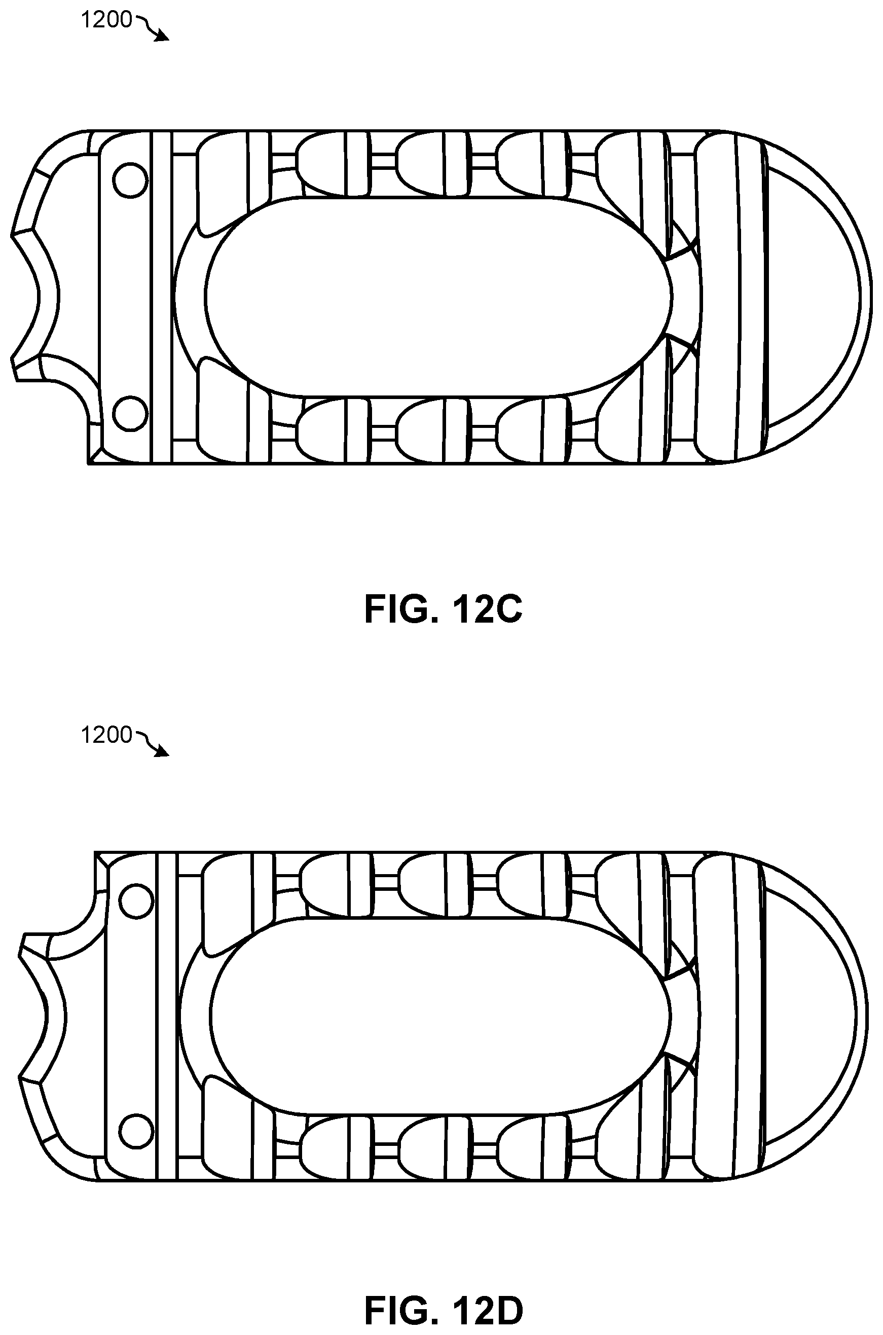
[0081] FIG. 12C is a top view of the intervertebral spacer 1200 of FIG. 12A;
[0082] FIG. 12D is a bottom view of the intervertebral spacer 1200 of FIG. 12A;
[0083] FIG. 12E illustrates a first side of the intervertebral spacer 1200 of FIG. 12A;
[0084] FIG. 12F illustrates a second side of the intervertebral spacer 1200 of FIG. 12A;
[0085] FIG. 12G illustrates the distal end of the intervertebral spacer 1200 of FIG. 12A;
[0086] FIG. 12H illustrates the proximal end of the intervertebral spacer 1200 of FIG. 12A;
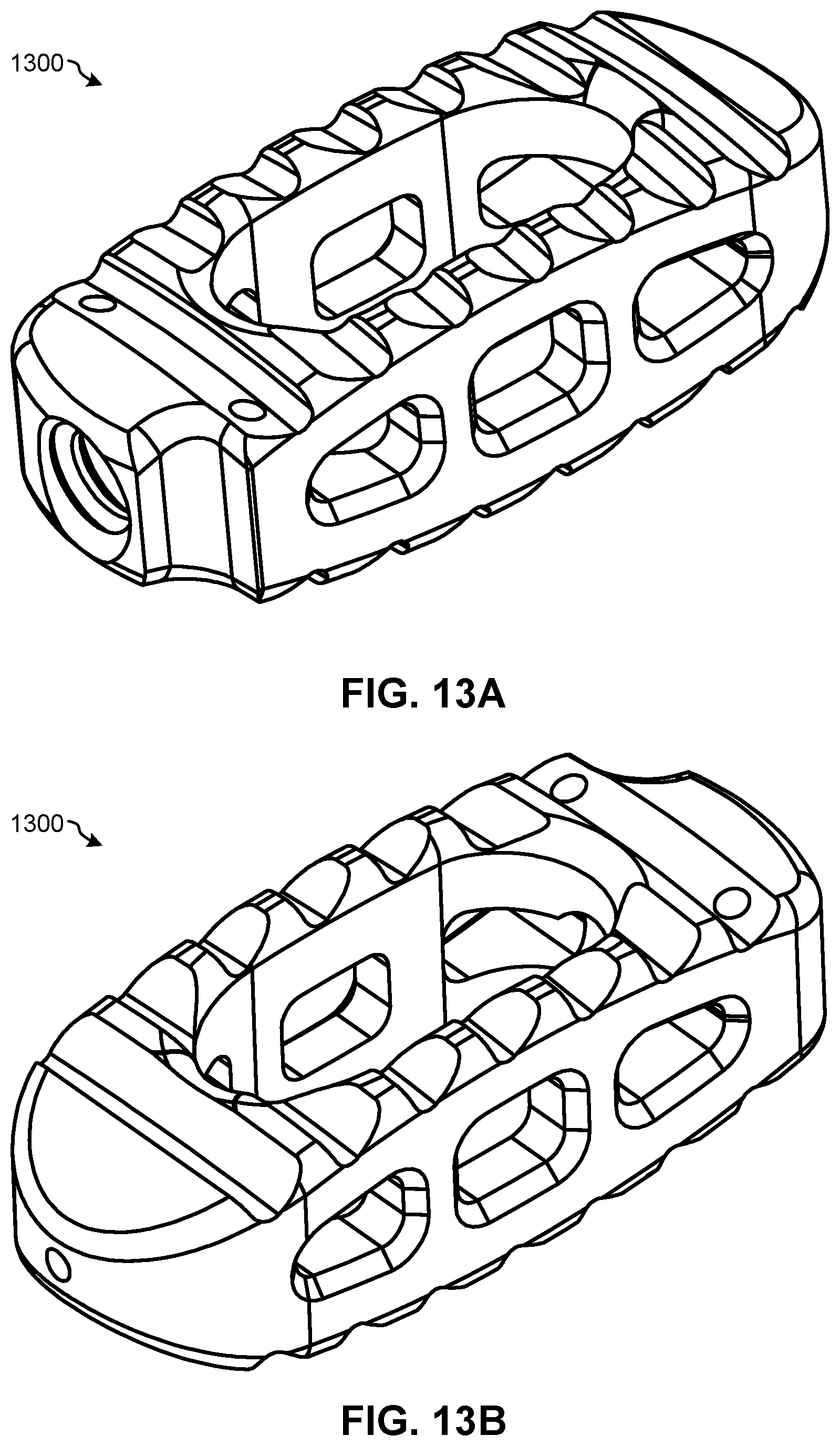
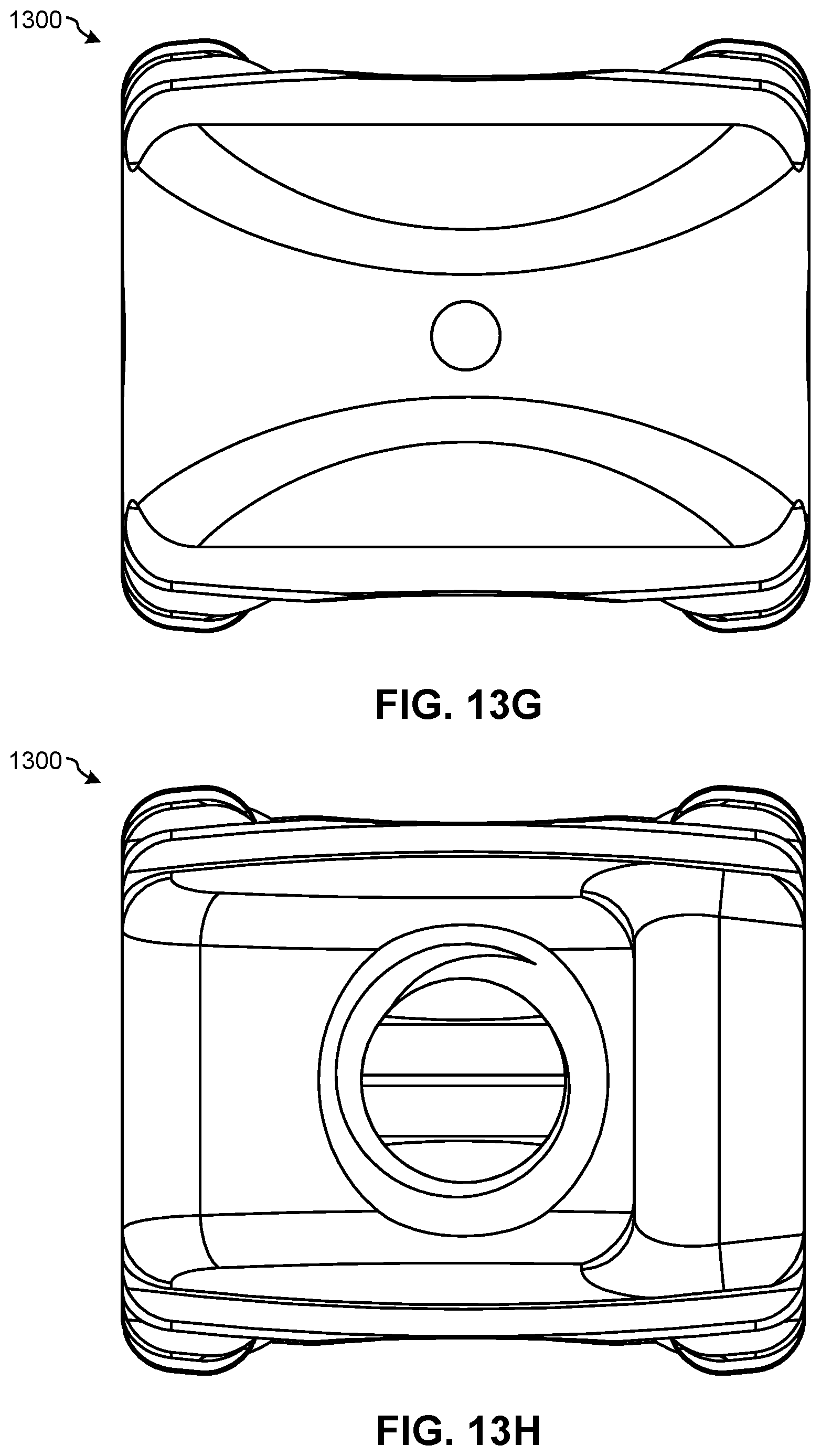
[0087] FIG. 13A is a perspective top view of a proximal end of an intervertebral spacer 1300, according to an embodiment of the present disclosure;
[0088] FIG. 13B is a perspective top view of a distal end of the intervertebral spacer 1300 of FIG. 13A;
[0089] FIG. 13C is a top view of the intervertebral spacer 1300 of FIG. 13A;
[0090] FIG. 13D is a bottom view of the intervertebral spacer 1300 of FIG. 13A;
[0091] FIG. 13E illustrates a first side of the intervertebral spacer 1300 of FIG. 13A;
[0092] FIG. 13F illustrates a second side of the intervertebral spacer 1300 of FIG. 13A;
[0093] FIG. 13G illustrates the distal end of the intervertebral spacer 1300 of FIG. 13A;
[0094] FIG. 13H illustrates the proximal end of the intervertebral spacer 1300 of FIG. 13A;
[0095] FIG. 14A is a perspective top view of a proximal end of an intervertebral spacer 1400, according to an embodiment of the present disclosure;
[0096] FIG. 14B is a perspective top view of a distal end of the intervertebral spacer 1400 of FIG. 14A;
[0097] FIG. 14C is a top view of the intervertebral spacer 1400 of FIG. 14A;
[0098] FIG. 14D is a bottom view of the intervertebral spacer 1400 of FIG. 14A;
[0099] FIG. 14E illustrates a first side of the intervertebral spacer 1400 of FIG. 14A;
[0100] FIG. 14F illustrates a second side of the intervertebral spacer 1400 of FIG. 14A;
[0101] FIG. 14G illustrates the distal end of the intervertebral spacer 1400 of FIG. 14A;
[0102] FIG. 14H illustrates the proximal end of the intervertebral spacer 1400 of FIG. 14A;
[0103] FIG. 15A is a perspective top view of a proximal end of an intervertebral spacer 1500, according to an embodiment of the present disclosure;
[0104] FIG. 15B is a perspective top view of a distal end of the intervertebral spacer 1500 of FIG. 15A;
[0105] FIG. 15C is a top view of the intervertebral spacer 1500 of FIG. 15A;
[0106] FIG. 15D is a bottom view of the intervertebral spacer 1500 of FIG. 15A;
[0107] FIG. 15E illustrates a first side of the intervertebral spacer 1500 of FIG. 15A;
[0108] FIG. 15F illustrates a second side of the intervertebral spacer 1500 of FIG. 15A;
[0109] FIG. 15G illustrates the distal end of the intervertebral spacer 1500 of FIG. 15A;
[0110] FIG. 15H illustrates the proximal end of the intervertebral spacer 1500 of FIG. 15A;
[0111] FIG. 16A is a perspective top view of a proximal end of an intervertebral spacer 1600, according to an embodiment of the present disclosure;
[0112] FIG. 16B is a perspective top view of a distal end of the intervertebral spacer 1600 of FIG. 16A;
[0113] FIG. 16C is a top view of the intervertebral spacer 1600 of FIG. 16A;
[0114] FIG. 16D is a bottom view of the intervertebral spacer 1600 of FIG. 16A;
[0115] FIG. 16E illustrates a first side of the intervertebral spacer 1600 of FIG. 16A;
[0116] FIG. 16F illustrates a second side of the intervertebral spacer 1600 of FIG. 16A;
[0117] FIG. 16G illustrates the distal end of the intervertebral spacer 1600 of FIG. 16A;
[0118] FIG. 16H illustrates the proximal end of the intervertebral spacer 1600 of FIG. 16A;
[0119] FIG. 17A is a perspective top view of a proximal end of an intervertebral spacer 1700, according to an embodiment of the present disclosure;
[0120] FIG. 17B is a perspective top view of a distal end of the intervertebral spacer 1700 of FIG. 17A;
[0121] FIG. 17C is a top view of the intervertebral spacer 1700 of FIG. 17A;
[0122] FIG. 17D is a bottom view of the intervertebral spacer 1700 of FIG. 17A;
[0123] FIG. 17E illustrates a first side of the intervertebral spacer 1700 of FIG. 17A;
[0124] FIG. 17F illustrates a second side of the intervertebral spacer 1700 of FIG. 17A;
[0125] FIG. 17G illustrates the distal end of the intervertebral spacer 1700 of FIG. 17A;
[0126] FIG. 17H illustrates the proximal end of the intervertebral spacer 1700 of FIG. 17A;
[0127] FIG. 18A is a perspective top view of a proximal end of an intervertebral spacer 1800, according to an embodiment of the present disclosure;
[0128] FIG. 18B is a perspective top view of a distal end of the intervertebral spacer 1800 of FIG. 18A;
[0129] FIG. 18C is a top view of the intervertebral spacer 1800 of FIG. 18A;
[0130] FIG. 18D is a bottom view of the intervertebral spacer 1800 of FIG. 18A;
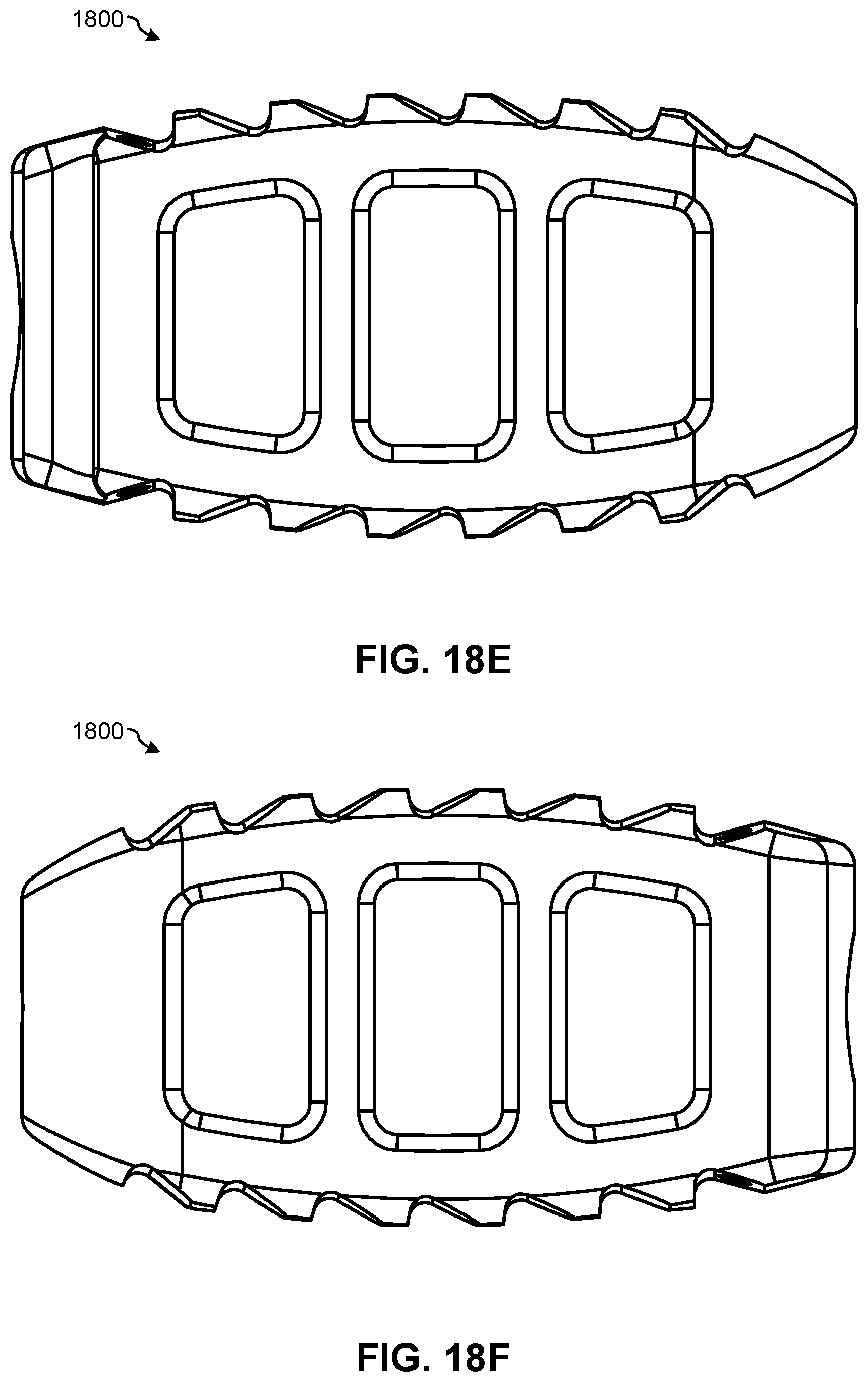
[0131] FIG. 18E illustrates a first side of the intervertebral spacer 1800 of FIG. 18A;
[0132] FIG. 18F illustrates a second side of the intervertebral spacer 1800 of FIG. 18A;
[0133] FIG. 18G illustrates the distal end of the intervertebral spacer 1800 of FIG. 18A;
[0134] FIG. 18H illustrates the proximal end of the intervertebral spacer 1800 of FIG. 18A;
[0135] FIG. 19A is a perspective top view of a proximal end of an inserter tool 1900, according to an embodiment of the present disclosure;
[0136] FIG. 19B is a perspective top view of a distal end of the inserter tool 1900 of FIG. 19A;
[0137] FIG. 19C is a top view of the inserter tool 1900 of FIG. 19A;
[0138] FIG. 19D is a bottom view of the inserter tool 1900 of FIG. 19A;
[0139] FIG. 19E is a right side view of the inserter tool 1900 of FIG. 19A;
[0140] FIG. 19F is a left side view of the inserter tool 1900 of FIG. 19A;
[0141] FIG. 19G illustrates the distal end 1912 of the inserter tool 1900 of FIG. 19A with an extended inserter shaft tip 1943;
[0142] FIG. 19H illustrates the distal end 1912 of the inserter tool 1900 of FIG. 19A with a retracted inserter shaft tip 1943;
[0143] FIG. 20A is a perspective side view of a proximal end of a shroud 1910 isolated from the inserter tool 1900 shown in FIG. 19A;
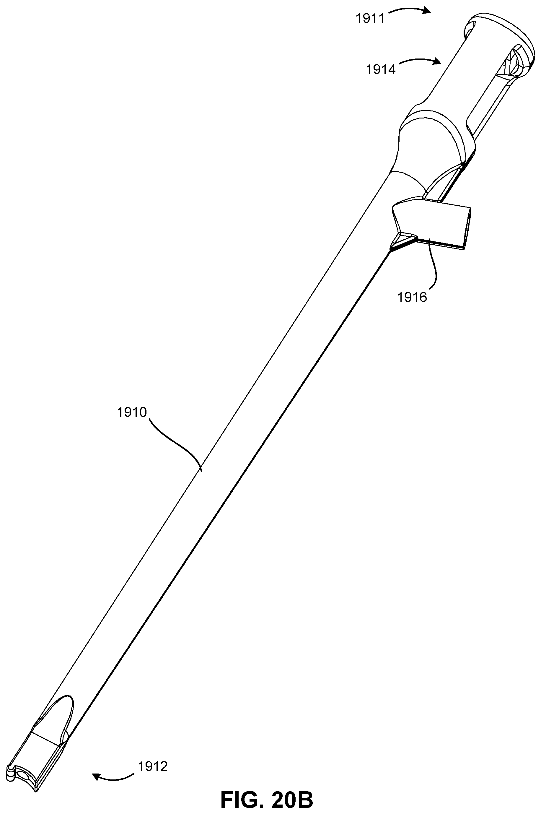
[0144] FIG. 20B is a perspective side view of a distal end of the shroud 1910 of FIG. 20A;
[0145] FIG. 20C is a close-up perspective view of the distal end of the shroud 1910 of FIG. 20A illustrating a cam lobe 1930;
[0146] FIG. 20D is a close-up side view of the distal end of the shroud 1910 of FIG. 20A illustrating the cam lobe 1930;
[0147] FIG. 21A is a perspective view of a proximal end of an inserter shaft 1940 isolated from the inserter tool 1900 shown in FIG. 19A;
[0148] FIG. 21B is a perspective view of a distal end of the inserter shaft 1940 of FIG. 21A;
[0149] FIG. 21C is a close-up perspective view of the distal end of the inserter shaft 1940 of FIG. 21A;
[0150] FIG. 21D is a close-up side view of the distal end of the inserter shaft 1940 of FIG. 21A;
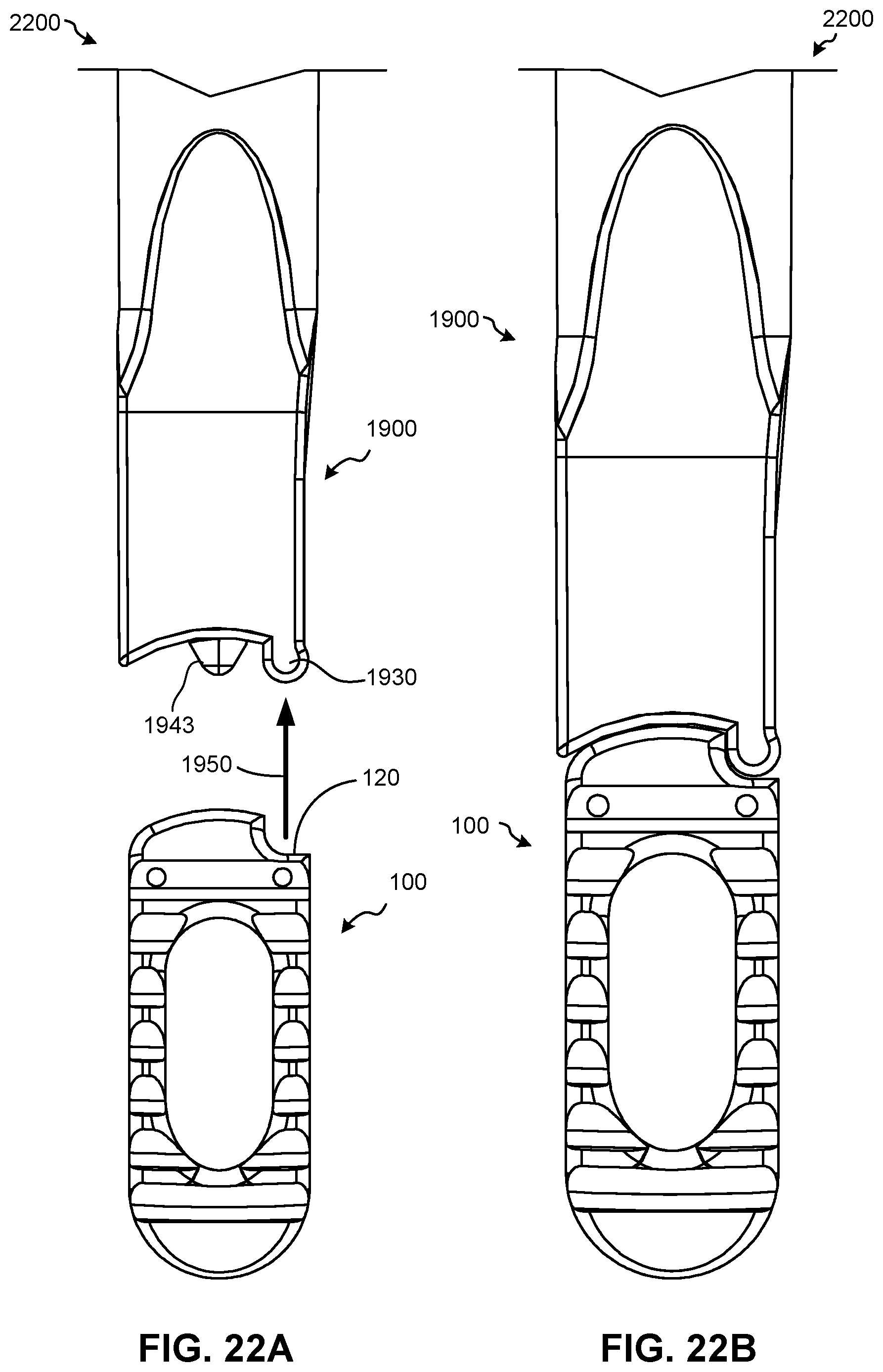
[0151] FIG. 22A illustrates a spinal fusion system 2200 prior to assembly;
[0152] FIG. 22B illustrates the spinal fusion system 2200 of FIG. 22A after assembly;
[0153] FIG. 23 illustrates a spinal fusion system 2300 with an intervertebral spacer 100 that has been partially rotated via a first force 1951;
[0154] FIG. 24 illustrates a spinal fusion system 2400 with an intervertebral spacer 100 that has been partially rotated via a first force 1951 and a second force 1952;
[0155] FIG. 25 illustrates a spinal fusion system 2500 with an intervertebral spacer 100 that has been fully rotated via a first force 1951;
[0156] FIG. 26 illustrates a spinal fusion system 2600 with an intervertebral spacer 100 that has been fully rotated via a first force 1951 and a second force 1952;
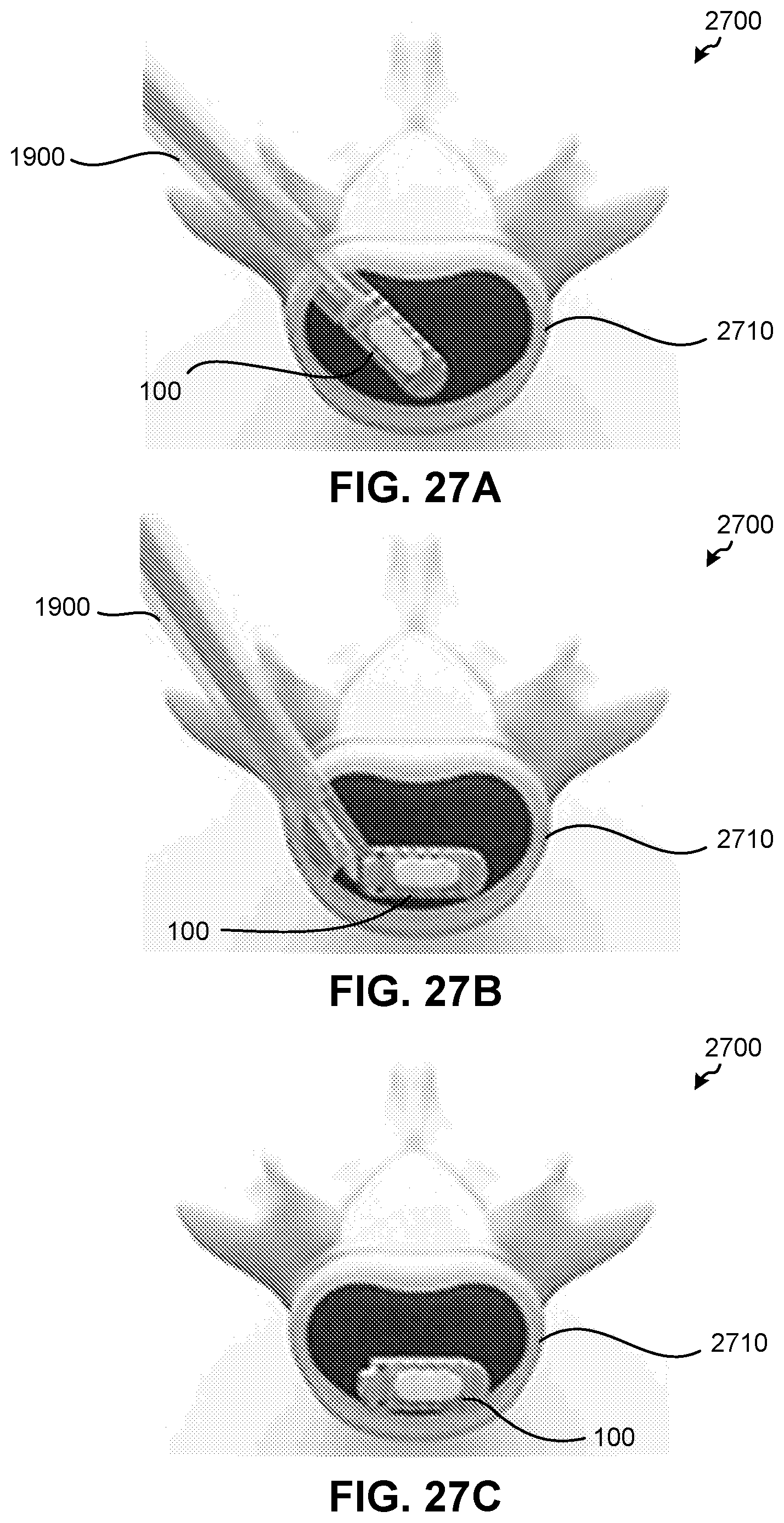
[0157] FIG. 27A illustrates an example implantation process 2700 for an intervertebral spacer 100 relative to a vertebral body 2710, according to one embodiment of the present disclosure;
[0158] FIG. 27B illustrates rotation of the intervertebral spacer 100 of FIG. 27A relative to the vertebral body 2710;
[0159] FIG. 27C illustrates final placement of the intervertebral spacer 100 of FIG. 27A relative to the vertebral body 2710;
[0160] FIG. 28A illustrates an example implantation process 2800 for one or more intervertebral spacers 100 relative to a vertebral body 2810, according to one embodiment of the present disclosure;
[0161] FIG. 28B illustrates final placement of two intervertebral spacers 100 relative to the vertebral body 2810; and
[0162] FIG. 29 illustrates a flowchart of a method 2900 for inserting an intervertebral spacer between two vertebral bodies of a patient, according to an embodiment of the present disclosure.
[0163] It is to be understood that the drawings are for purposes of illustrating the concepts of the disclosure and may not be drawn to scale. Furthermore, the drawings illustrate exemplary embodiments and do not represent limitations to the scope of the present disclosure.
DETAILED DESCRIPTION
[0164] Exemplary embodiments of the present disclosure will be best understood by reference to the drawings, wherein like parts are designated by like numerals throughout. It will be readily understood that the components of the present disclosure, as generally described and illustrated in the Figures herein, could be arranged and designed in a wide variety of different configurations. Thus, the following more detailed description of the embodiments of the apparatus and method, as represented in the Figures, is not intended to limit the scope of the present disclosure, as claimed in this or any other application claiming priority to this application, but is merely representative of exemplary embodiments of the present disclosure.
[0165] Standard medical directions, planes of reference, and descriptive terminology are employed in this specification. For example, anterior means toward the front of the body. Posterior means toward the back of the body. Superior means toward the head. Inferior means toward the feet. Medial means toward the midline of the body. Lateral means away from the midline of the body. Axial means toward a central axis of the body. Abaxial means away from a central axis of the body. Ipsilateral means on the same side of the body. Contralateral means on the opposite side of the body. A sagittal plane divides a body into right and left portions. A midsagittal plane divides the body into bilaterally symmetric right and left halves. A coronal plane divides a body into anterior and posterior portions. A transverse plane divides a body into superior and inferior portions. These descriptive terms may be applied to an animate or inanimate body.
[0166] The phrases "connected to," "coupled to," "engaged with," and "in communication with" refer to any form of interaction between two or more entities, including mechanical, electrical, magnetic, electromagnetic, fluid, and thermal interaction. Two components may be functionally coupled to each other even though they are not in direct contact with each other. The term "abutting" refers to items that are in direct physical contact with each other, although the items may not necessarily be attached together. The phrase "fluid communication" refers to two features that are connected such that a fluid within one feature is able to pass into the other feature.
[0167] The word "exemplary" is used herein to mean "serving as an example, instance, or illustration." Any embodiment described herein as "exemplary" is not necessarily to be construed as preferred or advantageous over other embodiments. While the various aspects of the embodiments are presented in drawings, the drawings are not necessarily drawn to scale unless specifically indicated.
[0168] FIGS. 1A-1H illustrate various views of an intervertebral spacer 100, according to an embodiment of the present disclosure. Specifically, FIG. 1A is a perspective top view of a proximal end 105 of the intervertebral spacer 100; FIG. 1B is a perspective top view of a distal end 104 of the intervertebral spacer 100; FIG. 1C is a top view of the intervertebral spacer 100; FIG. 1D is a bottom view of the intervertebral spacer 100; FIG. 1E illustrates a first side 111 of the intervertebral spacer 100; FIG. 1F illustrates a second side 112 of the intervertebral spacer 100; FIG. 1G is a perspective view of the distal end 104 of the intervertebral spacer 100; and FIG. 1H is a perspective view of the proximal end 105 of the intervertebral spacer 100.
[0169] The intervertebral spacer 100 may generally include a superior surface 101 configured to engage a superior vertebral body (not shown), an inferior surface 102 configured to engage an inferior vertebral body (not shown), and a peripheral wall 103 extending from the superior surface 101 to the inferior surface 102. The peripheral wall 103 may generally comprise the distal end 104, the proximal end 105, the first side 111, and the second side 112 of the intervertebral spacer 100.
[0170] The proximal end 105 of the intervertebral spacer 100 may include a cam surface 120 that is rotatable against a complementary cam surface of a suitable inserter tool such that a first force causes the intervertebral spacer 100 to pivot, relative to the inserter tool, about a pivot point 125 associated with the cam surface 120, as will be discussed in more detail below with respect to FIGS. 22A-26. The cam surface 120 may comprise a concave surface having a first radius of curvature 121, as shown in FIGS. 1C and 1D. In at least one embodiment, the first radius of curvature 121 may be about 1.25 mm. In other embodiments, the first radius of curvature 121 may be between about 0.5 mm and about 4 mm. However, it will be understood that in other embodiments (not shown), the cam surface 120 may alternatively comprise a convex surface. The cam surface 120 may also be located closer to the first side 111 of the intervertebral spacer 100 than the second side 112 of the intervertebral spacer 100, or vice versa.
[0171] The proximal end 105 of the intervertebral spacer 100 may also include an aperture 140 formed therein, as well as a chamfered surface 142 proximate the aperture 140. The chamfered surface 142 may be configured to receive a second force from a suitable inserter shaft tip to aid the first force in pivoting the intervertebral spacer 100 about the pivot point 125 associated with the cam surface 120, as will be discussed in more detail below with respect to FIGS. 22A-26. Moreover, the aperture 140 may include threading 144 formed within the aperture 140 to facilitate coupling of the intervertebral spacer 100 to a suitable inserter shaft, which will also be discussed in more detail below with respect to FIGS. 22A-26.
[0172] As shown in FIG. 1E, the superior surface 101 of the intervertebral spacer 100 may comprise a third radius of curvature 113 that extends from the proximal end 105 of the intervertebral spacer 100 to the distal end 104 of the intervertebral spacer 100. Likewise, the inferior surface 102 of the intervertebral spacer 100 may comprise a fourth radius of curvature 114 that extends from the proximal end 105 of the intervertebral spacer 100 to the distal end 104 of the intervertebral spacer 100, as shown in FIG. 1F.
[0173] In at least one embodiment, the fourth radius of curvature 114 may be substantially equal to the third radius of curvature 113. As defined herein, "substantially equal to" means "equal to," or within about a + or -10% relative variance from one another.
[0174] In some embodiments, the third and fourth radii of curvatures 113, 114 may each range from about 300 mm to about 60 mm.
[0175] In a particular embodiment, the third and fourth radii of curvatures 113, 114 may each be about 42.45 mm.
[0176] As shown in FIG. 1G, the superior surface 101 of the intervertebral spacer 100 may comprise a fifth radius of curvature 115 that extends from the first side 111 of the intervertebral spacer 100 to the second side 112 of the intervertebral spacer 100. Likewise, the inferior surface 102 of the intervertebral spacer 100 may comprise a sixth radius of curvature 116 that extends from the first side 111 of the intervertebral spacer 100 to the second side 112 of the intervertebral spacer 100, as shown in FIG. 1H.
[0177] In at least one embodiment, the sixth radius of curvature 116 may be substantially equal to the fifth radius of curvature 115.
[0178] In some embodiments, the fifth and sixth radii of curvatures 115, 116 may each range from about 300 mm to about 60 mm.
[0179] In a particular embodiment, fifth and sixth radii of curvatures 115, 116 may each be about 41.5 mm.
[0180] In this manner, the third, fourth, fifth, and sixth radii of curvatures 113, 114, 115, 116 of the superior and inferior surfaces 101, 102 of the intervertebral spacer 100 may together result in a dome shape with "high spots" (or maximal thickness of the intervertebral spacer 100) toward the centers of the superior and inferior surfaces 101, 102. These high spots may help reduce frictional forces acting upon the superior and inferior surfaces 101, 102 when the intervertebral spacer 100 is inserted between two vertebral bodies. In this manner, these high spots may help reduce the force needed to rotate the intervertebral spacer 100 after it has been inserted between two vertebral bodies, as will be discussed below in more detail with respect to FIGS. 22A-26.
[0181] The intervertebral spacer 100 may include a central bone graft aperture 160 formed through the superior and inferior surfaces 101, 102 of the intervertebral spacer 100, as well as one or more side bone graft apertures 170 formed in the first and second sides 111, 112 of the intervertebral spacer 100. The central bone graft aperture 160 and the one or more side bone graft apertures 170 may each be configured to receive bone graft material (not shown) and/or other suitable materials that are known in the art. The intervertebral spacer 100 may also include one or more serrated teeth 180 formed in the superior and inferior surfaces 101, 102 of the intervertebral spacer 100. The one or more serrated teeth 180 may be configured to help stabilize the intervertebral spacer 100 between adjacent vertebral bodies during the fusion process. Moreover, bone graft and/or other suitable materials may also be placed between adjacent serrated teeth 180 of the intervertebral spacer 100 in order to enhance the fusion process and/or help stabilize the intervertebral spacer 100 between adjacent vertebral bodies during the fusion process.
[0182] The intervertebral spacer 100 may also include one or more first marker apertures 150 and a second marker aperture 152. The one or more first marker apertures 150 may each be configured to receive a first radiopaque maker 200, as shown in FIGS. 2A and 2B. The second marker aperture 152 may be configured to receive a second radiopaque maker 300, as shown in FIGS. 3A and 3B. The first and second radiopaque makers 200, 300 may be made from any suitable radiopaque material, such as tantalum (as one non-limiting example). The first and second radiopaque makers 200, 300 may be respectively inserted into the first and second marker apertures 150, 152 in order to couple the first and second radiopaque makers 200, 300 to the intervertebral spacer 100, as can be seen in the exploded view shown in FIG. 4. In this manner, the first and second radiopaque makers 200, 300 may be used to verify whether or not the intervertebral spacer 100 has been correctly placed between adjacent vertebral bodies via a suitable x-ray imaging process, which may be performed intraoperatively and/or postoperatively.
[0183] FIGS. 5A-18H illustrate various views of differently sized intervertebral spacers, according to embodiments of the present disclosure. Specifically, FIGS. 5A-5H illustrate various views of an intervertebral spacer 500 having a height "H" (see FIG. 5E) of about 8 mm and a length "L" (see FIG. 5E) of about 22 mm; FIGS. 6A-6H illustrate various views of an intervertebral spacer 600 having a height of about 9 mm and a length of about 22 mm; FIGS. 7A-7H illustrate various views of an intervertebral spacer 700 having a height of about 10 mm and a length of about 22 mm; FIGS. 8A-8H illustrate various views of an intervertebral spacer 800 having a height of about 11 mm and a length of about 22 mm; FIGS. 9A-9H illustrate various views of an intervertebral spacer 900 having a height of about 12 mm and a length of about 22 mm; FIGS. 10A-10H illustrate various views of an intervertebral spacer 1000 having a height of about 13 mm and a length of about 22 mm; FIGS. 11A-11H illustrate various views of an intervertebral spacer 1100 having a height of about 14 mm and a length of about 22 mm; FIGS. 12A-12H illustrate various views of an intervertebral spacer 1200 having a height of about 8 mm and a length of about 26 mm; FIGS. 13A-13H illustrate various views of an intervertebral spacer 1300 having a height of about 9 mm and a length of about 26 mm; FIGS. 14A-14H illustrate various views of an intervertebral spacer 1400 having a height of about 10 mm and a length of about 26 mm; FIGS. 15A-15H illustrate various views of an intervertebral spacer 1500 having a height of about 11 mm and a length of about 26 mm; FIGS. 16A-16H illustrate various views of an intervertebral spacer 1600 having a height of about 12 mm and a length of about 26 mm; FIGS. 17A-17H illustrate various views of an intervertebral spacer 1700 having a height of about 13 mm and a length of about 26 mm; and FIGS. 18A-18H illustrate various views of an intervertebral spacer 1800 having a height of about 14 mm and a length of about 26 mm.
[0184] FIGS. 19A-21D illustrate various views of an inserter tool 1900 and its components, according to an embodiment of the present disclosure. Specifically, FIG. 19A is a perspective top view of a proximal end 1911 of the inserter tool 1900; FIG. 19B is a perspective top view of a distal end 1912 of the inserter tool 1900; FIG. 19C is a top view of the inserter tool 1900; FIG. 19D is a bottom view of the inserter tool 1900; FIG. 19E is a right side view of the inserter tool 1900; FIG. 19F is a left side view of the inserter tool 1900; FIG. 19G illustrates the distal end 1912 of the inserter tool 1900 with an extended inserter shaft tip 1943; FIG. 19H illustrates the distal end 1912 of the inserter tool 1900 with a retracted inserter shaft tip 1943; FIG. 20A is a perspective side view of the proximal end 1911 of a shroud 1910 of the inserter tool 1900; FIG. 20B is a perspective side view of the distal end 1912 of the shroud 1910; FIG. 20C is a close-up perspective view of the distal end 1912 of the shroud 1910 illustrating a cam lobe 1930; FIG. 20D is a close-up side view of the distal end 1912 of the shroud 1910 illustrating the cam lobe 1930; FIG. 21A is a perspective view of a proximal end 1941 of an inserter shaft 1940 of the inserter tool 1900; FIG. 21B is a perspective view of a distal end 1942 of the inserter shaft 1940; FIG. 21C is a close-up perspective view of the distal end 1942 of the inserter shaft 1940; and FIG. 21D is a close-up side view of the distal end 1942 of the inserter shaft 1940.
[0185] As shown in FIGS. 19A-21D, the inserter tool 1900 may generally comprise the shroud 1910, the inserter shaft 1940 (enclosed by the shroud 1910), a handle 1920 located toward the proximal end 1911 of the shroud 1910, and the cam lobe 1930 located at the distal end 1912 of the shroud 1910. The handle 1920 may be coupled to the shroud 1910 via a shroud stem 1916 (see FIGS. 20A and 20B) and the shroud 1910 may generally extend between the handle 1920 and the cam lobe 1930.
[0186] As shown in FIGS. 21A-21D, the inserter shaft 1940 may be coupled to a knob 1945 at its proximal end 1941 and have the inserter shaft tip 1943 at its distal end 1942. The knob 1945 may be accessible through a window 1914 formed in the shroud 1910 (see FIGS. 20A and 20B). The knob 1945 may be translated distally with respect to the shroud 1910 (as indicated by arrow 1901 shown in FIG. 19E) to extend the inserter shaft tip 1943 from the distal end 1912 of the shroud 1910 through the inserter shaft aperture 1918 (see FIG. 20C). The knob 1945 may also be translated proximally with respect to the shroud 1910 (as indicated by arrow 1902 shown in FIG. 19F) to retract the inserter shaft tip 1943 into the distal end 1912 of the shroud 1910.
[0187] As shown in FIGS. 21C-21D, the inserter shaft tip 1943 may have a conical shape that is configured to engage the chamfered surface 142 formed in the intervertebral spacer 100, as will be discussed in more detail below with respect to FIGS. 22A-26. The inserter shaft 1940 may also include threading 1944 formed along the inserter shaft 1940 proximate the inserter shaft tip 1943. In this manner, the inserter shaft 1940 may be removably couplable to the intervertebral spacer 100 by rotating the inserter shaft 1940 relative to the intervertebral spacer 100 to engage the threading 1944 of the inserter shaft 1940 (i.e., first threading) with the threading 144 formed in the intervertebral spacer 100 (i.e., second threading).
[0188] As shown in FIGS. 20C-20D, the cam lobe 1930 may comprise a complementarily shaped convex cam lobe surface 1931 having a second radius of curvature 1932 that is substantially equal to the first radius of curvature 121 shown in FIGS. 1C and 1D. However, it will be understood that in other embodiments, the cam lobe 1930 may alternatively comprise a concave surface that is complementarily shaped to a convex cam surface formed in a suitable intervertebral spacer (not shown).
[0189] In this application, surfaces that are "complementary" or "complementarily shaped" are surfaces that are shaped to follow similar pathways. In some embodiments, complementarily shaped surfaces may be concave and convex, respectively, Further, in some exemplary embodiment, complementarily shaped surfaces may have arcuate shapes. The radii of curvature of complementarily shaped surfaces may be similar, for example, with the surface having a concave curvature having a radius of curvature slightly larger than the radius of curvature of the convex surface. However, complementary surfaces, or complementarily shaped surfaces, need not, in all embodiments, be concave and convex (respectively), arcuate, or possessed of similar radii of curvature.
[0190] In at least one embodiment, the cam lobe 1930 may be located closer to the top of the shroud 1910 above a distal surface 1919. In this embodiment, the distal surface 1919 of the shroud 1910 may be concave. However, it will also be understood that in other embodiments (not shown), the cam lobe 1930 may be located closer to the bottom of the shroud 1910 below a distal surface of the shroud 1910, and the distal surface of the shroud 1910 may be at least partially concave, convex, and/or straight.
[0191] FIGS. 22A-26 illustrate various spinal fusion systems including an intervertebral spacer 100 and an inserter tool 1900 during various stages of operation. Specifically, FIG. 22A illustrates a spinal fusion system 2200 prior to assembly; FIG. 22B illustrates the spinal fusion system 2200 after assembly; FIG. 23 illustrates a spinal fusion system 2300 with the intervertebral spacer 100 partially rotated via a first force 1951; FIG. 24 illustrates a spinal fusion system 2400 with the intervertebral spacer 100 partially rotated via the first force 1951 and a second force 1952; FIG. 25 illustrates a spinal fusion system 2500 with the intervertebral spacer 100 fully rotated via the first force 1951; and FIG. 26 illustrates a spinal fusion system 2600 with the intervertebral spacer 100 fully rotated via the first force 1951 and the second force 1952.
[0192] FIGS. 22A and 22B illustrate how the intervertebral spacer 100 may be removably coupled to the inserter tool 1900. This may be accomplished by aligning the cam surface 120 with the cam lobe 1930, moving the cam surface 120 into engagement with the complimentarily shaped cam lobe 1930 (see arrow 1950 in FIG. 22A), and engaging the threading 1944 of the inserter shaft 1940 with the threading 144 of the intervertebral spacer 100 to removably couple the intervertebral spacer 100 to the inserter shaft 1940 (and thus the inserter tool 1900), as shown in FIG. 22B.
[0193] FIGS. 23 and 25 illustrate how the cam surface 120 of the intervertebral spacer 100 is rotatable against the complementary cam lobe surface 1931 of the cam lobe 1930 coupled to the inserter tool 1900, such that a first force 1951 causes the intervertebral spacer 100 to pivot, relative to the inserter tool 1900, about the pivot point 125 associated with the cam surface 120. In these embodiments, the cam lobe 1930 is configured to impart the first force 1951 to the cam surface 120 as the inserter tool 1900 is pushed distally, causing the intervertebral spacer 100 to pivot about the pivot point 125 associated with the cam surface 120. As previously discussed, frictional forces may act upon the superior and inferior surfaces 101, 102 of the intervertebral spacer 100 when it is inserted between two vertebral bodies. In this manner, the frictional forces imparted on the intervertebral spacer 100 by the vertebral bodies may act to oppose the first force 1951 and help facilitate rotation of the intervertebral spacer 100 as it is inserted between the vertebral bodies.
[0194] FIGS. 24 and 26 show how the chamfered surface 142 of the intervertebral spacer 100 is configured to receive a second force 1952 from the inserter shaft tip 1943 to further aid the first force 1951 in pivoting the intervertebral spacer 100 about the pivot point 125 associated with the cam surface 120. This may be accomplished by pushing the inserter shaft 1940 distally, causing the inserter shaft tip 1943 to engage the chamfered surface 142 of the intervertebral spacer 100 and pivot the intervertebral spacer 100 about the pivot point 125 associated with the cam surface 120. In a similar manner, the frictional forces imparted on the intervertebral spacer 100 by the vertebral bodies may act to oppose both of the first and second forces 1951, 1952 and help facilitate rotation of the intervertebral spacer 100 as it is inserted between the vertebral bodies.
[0195] FIGS. 27A-27C illustrate an example implantation process 2700 for an intervertebral spacer 100 relative to a vertebral body 2710, according to one embodiment of the present disclosure. Specifically, FIG. 27A illustrates the intervertebral spacer 100 inserted into the disc space above the vertebral body 2710 during a transforaminal insertion procedure; FIG. 27B illustrates rotation of the intervertebral spacer 100 relative to the vertebral body 2710 via one or more of the processes described above with respect to FIGS. 23-26; and FIG. 27C illustrates final placement of the intervertebral spacer 100 relative to the vertebral body 2710 with the inserter tool 1900 decoupled from the intervertebral spacer 100 and removed from the surgical site.
[0196] FIGS. 28A and 28B illustrate another example implantation process 2800 for one or more intervertebral spacers 100 relative to a vertebral body 2810, according to another embodiment of the present disclosure. Specifically, FIG. 28A illustrates one intervertebral spacer 100 inserted into the disc space above the vertebral body 2810 during a posterior insertion procedure, with the aid of a tool 3000 providing distraction during the insertion process, and FIG. 28B illustrates final placement of two intervertebral spacers 100 relative to the vertebral body 2810.
[0197] FIG. 29 illustrates a flowchart of a method 2900 for inserting an intervertebral spacer between two vertebral bodies of a patient, according to an embodiment of the present disclosure. In general, the method 2900 may include the use of an intervertebral spacer comprising a cam surface and an inserter tool that comprises a complimentarily shaped cam lobe configured to engage the cam surface and permit selective rotation of the intervertebral spacer relative to the inserter tool. The inserter tool may also comprise an inserter shaft with first threading and the intervertebral spacer may additionally comprises an aperture with second threading. The inserter shaft further comprise an inserter shaft tip and the intervertebral spacer may also comprise a chamfered surface proximate the aperture.
[0198] The method 2900 may begin with a step 2910 in which the cam surface of the intervertebral spacer may be aligned with the complimentarily shaped cam lobe of the inserter tool.
[0199] Once the cam surface of the intervertebral spacer has been aligned with the complimentarily shaped cam lobe of the inserter tool, the method 2900 may proceed to a step 2920 in which the cam surface may be moved into engagement with the complimentarily shaped cam lobe and the first threading of the inserter shaft may be engaged with the second threading of the intervertebral spacer to removably couple the intervertebral spacer to the inserter shaft.
[0200] Once the intervertebral spacer has been removably coupled to the inserter shaft, the method 2900 may proceed to a step 2930 in which the intervertebral spacer may be inserted between the two vertebral bodies of the patient.
[0201] Alternatively, or in addition thereto, once the intervertebral spacer has been inserted between the two vertebral bodies of the patient, the method 2900 may proceed to a step 2940 in which a first force may be applied to the cam surface with the complimentarily shaped cam lobe to cause the intervertebral spacer to pivot, relative to the inserter tool, about a pivot point associated with the cam surface.
[0202] Alternatively, or in addition thereto, the method 2900 may proceed to a step 2950 in which a second force may be applied to the chamfered surface with the inserter shaft tip to aid the first force in pivoting the intervertebral spacer about the pivot point associated with the cam surface.
[0203] Alternatively, or in addition thereto, the method 2900 may proceed to a step 2960 in which the first threading of the inserter shaft may be disengaged with the second threading of the intervertebral spacer, the inserter shaft may be removed from the patient, and the method 2900 may end.
[0204] Any methods disclosed herein comprise one or more steps or actions for performing the described method. One or more of the method steps and/or actions may be omitted from and of the methods disclosed herein. Moreover, any of the method steps and/or actions may be interchanged with one another. In other words, unless a specific order of steps or actions is required for proper operation of the embodiment, the order and/or use of specific steps and/or actions may be modified.
[0205] Reference throughout this specification to "an embodiment" or "the embodiment" means that a particular feature, structure or characteristic described in connection with that embodiment is included in at least one embodiment. Thus, the quoted phrases, or variations thereof, as recited throughout this specification are not necessarily all referring to the same embodiment.
[0206] Similarly, it should be appreciated that in the above description of embodiments, various features are sometimes grouped together in a single embodiment, Figure, or description thereof for the purpose of streamlining the disclosure. This method of disclosure, however, is not to be interpreted as reflecting an intention that any claim requires more features than those expressly recited in that claim. Rather, as the following claims reflect, inventive aspects lie in a combination of fewer than all features of any single foregoing disclosed embodiment. Thus, the claims following this Detailed Description are hereby expressly incorporated into this Detailed Description, with each claim standing on its own as a separate embodiment. This disclosure includes all permutations of the independent claims with their dependent claims.
[0207] Recitation in the claims of the term "first" with respect to a feature or element does not necessarily imply the existence of a second or additional such feature or element. Elements recited in means-plus-function format are intended to be construed in accordance with 35 U.S.C. .sctn. 112 Para. 6. It will be apparent to those having skill in the art that changes may be made to the details of the above-described embodiments without departing from the underlying principles set forth herein.
[0208] While specific embodiments and applications of the present disclosure have been illustrated and described, it is to be understood that the scope of the appended claims is not limited to the precise configuration and components disclosed herein. Various modifications, changes, and variations which will be apparent to those skilled in the art may be made in the arrangement, operation, and details of the systems, methods, and devices disclosed herein.
* * * * *
D00000
D00001
D00002
D00003
D00004
D00005
D00006
D00007
D00008
D00009
D00010
D00011
D00012

D00013

D00014

D00015

D00016
D00017

D00018

D00019
D00020

D00021

D00022

D00023

D00024

D00025

D00026

D00027

D00028

D00029

D00030

D00031

D00032

D00033

D00034

D00035

D00036
D00037

D00038

D00039
D00040

D00041

D00042
D00043

D00044

D00045

D00046

D00047

D00048

D00049

D00050

D00051

D00052

D00053

D00054

D00055

D00056

D00057

D00058

D00059

D00060

D00061
D00062

D00063

D00064

D00065

D00066

D00067

D00068

D00069

D00070
D00071

D00072

D00073

D00074

D00075
D00076

D00077

D00078

D00079
D00080

D00081

XML
uspto.report is an independent third-party trademark research tool that is not affiliated, endorsed, or sponsored by the United States Patent and Trademark Office (USPTO) or any other governmental organization. The information provided by uspto.report is based on publicly available data at the time of writing and is intended for informational purposes only.
While we strive to provide accurate and up-to-date information, we do not guarantee the accuracy, completeness, reliability, or suitability of the information displayed on this site. The use of this site is at your own risk. Any reliance you place on such information is therefore strictly at your own risk.
All official trademark data, including owner information, should be verified by visiting the official USPTO website at www.uspto.gov. This site is not intended to replace professional legal advice and should not be used as a substitute for consulting with a legal professional who is knowledgeable about trademark law.