Multi-electrode Irrigated Balloon Catheter
Pappone; Carlo ; et al.
U.S. patent application number 16/543277 was filed with the patent office on 2020-02-06 for multi-electrode irrigated balloon catheter. The applicant listed for this patent is ST. JUDE MEDICAL, ATRIAL FIBRILLATION DIVISION, INC.. Invention is credited to Peter Chen, Alan de la Rama, Cary Hata, Carlo Pappone.
| Application Number | 20200038103 16/543277 |
| Document ID | / |
| Family ID | 39827599 |
| Filed Date | 2020-02-06 |


| United States Patent Application | 20200038103 |
| Kind Code | A1 |
| Pappone; Carlo ; et al. | February 6, 2020 |
MULTI-ELECTRODE IRRIGATED BALLOON CATHETER
Abstract
A fluid delivery balloon ablation catheter configured to allow uniform fluid distribution through each electrode by varying the diameter of the main lumen. The catheter comprises an elongated tubular catheter body having a distal end, a proximal end, and a lumen extending longitudinally within the catheter body. A number of elution holes are provided in the catheter tip region, and these holes are in fluid communication with the lumen through ducts. As such, cooling fluid is delivered from the pump, through the lumen through the ducts, and out of the holes to the environment outside of the catheter. The main lumen has at least one tapered flow constrictors to restrict flow of fluid towards the distal region of the lumen. The catheter has multiple half-dome balloons, with the distal balloon being the smallest, and the proximal balloon being the largest balloon. The multiple-balloon catheter helps when using the ablation catheter in a funnel-shaped vessel.
| Inventors: | Pappone; Carlo; (Lecco, IT) ; de la Rama; Alan; (Cerritos, CA) ; Chen; Peter; (Irvine, CA) ; Hata; Cary; (Irvine, CA) | ||||||||||
| Applicant: |
|
||||||||||
|---|---|---|---|---|---|---|---|---|---|---|---|
| Family ID: | 39827599 | ||||||||||
| Appl. No.: | 16/543277 | ||||||||||
| Filed: | August 16, 2019 |
Related U.S. Patent Documents
| Application Number | Filing Date | Patent Number | ||
|---|---|---|---|---|
| 14288017 | May 27, 2014 | 10433903 | ||
| 16543277 | ||||
| 11696646 | Apr 4, 2007 | 8764742 | ||
| 14288017 | ||||
| Current U.S. Class: | 1/1 |
| Current CPC Class: | A61M 25/003 20130101; A61M 2025/1093 20130101; A61M 2025/0034 20130101; A61M 25/1011 20130101; A61B 2018/1497 20130101; A61B 2018/1467 20130101; A61B 2018/00029 20130101; A61M 25/007 20130101; A61B 2218/002 20130101; A61B 18/1492 20130101; A61M 25/1002 20130101; A61M 25/0071 20130101 |
| International Class: | A61B 18/14 20060101 A61B018/14; A61M 25/10 20060101 A61M025/10; A61M 25/00 20060101 A61M025/00 |
Claims
1. A balloon catheter comprising: a catheter body having a lumen with varied diameter along a longitudinal length; a pump attached to a proximal end of the catheter for infusing a fluid through the lumen; a plurality of ducts each leading from the lumen to a separate hole on an exterior surface of the catheter such that a fluid can pass through the lumen, through the ducts, and eventually flow out of the holes for fluid delivery in a patient; wherein the diameter of the catheter lumen is varied such that a desired delivery pattern is achieved due to the differences of fluid pressure along the longitudinal length caused by the varied diameter.
2. The balloon catheter of claim 1, wherein the desired delivery pattern is to have a uniformed outflow rate of fluid in substantially all of the holes, and wherein the diameter of the lumen is smaller at its distal end than at its proximal end.
3. The balloon catheter of claim 2 further comprising at least one RF ablation electrode at a distal end, means for electrically connecting the electrode to a RF ablation current generating means, a temperature sensor attached to a tip of the catheter for generating a signal indicative of the temperature of the electrode, and wherein the fluid is a cooling fluid for irrigating the electrode and substantially evenly dissipate beat throughout the entire length of a catheter tip or ring electrodes.
4. The balloon catheter of claim 3, wherein the desired delivery pattern is to have an outflow rate of fluid that is faster at the distal cod of the catheter than its proximal end.
5. The balloon catheter of claim 1, wherein the desired delivery pattern is to have an outflow rate of fluid that is slower at the distal end of the catheter than its proximal end.
6. The balloon catheter of claim 1, wherein the desired delivery pattern is to have an overall uniform outflow rate except at least one longitudinal section of holes with a different outflow rate, wherein the different outflow rate is either faster or slower than the uniform outflow rate.
7. The balloon catheter of claim 1 further comprising at least one inflatable balloon disposed on the catheter body.
8. The balloon catheter of claim 7, wherein one of the at least one inflatable balloon is attached to less than 60% of a circumference of a section of the catheter body.
9. The balloon catheter of claim 8, wherein one of the at least one inflatable balloon is attached to less than 52% of a circumference of a section of the catheter body.
10. The balloon catheter of claim 9, wherein one of the at least one inflatable balloon has an inflated shape, wherein the inflated shape is a half-dome.
11. The balloon catheter of claim 10 further comprising a plurality of balloons, and where the inflatable balloon located most distally has an inflated size that is smaller than an inflated size of some of the other inflatable balloons.
12. The balloon catheter of claim 11, wherein the desired delivery pattern is to have a uniformed outflow rate of fluid in substantially all of the holes, and wherein the diameter of the lumen is smaller at its distal end than at its proximal end.
13. The balloon catheter of claim 12, wherein the fluid is at least one selected from the group consisting of cooling fluid, therapeutic fluid, medication.
14. The balloon catheter of claim 13, wherein the plurality of holes are disposed opposite the plurality of balloons on the catheter body, such that each inflatable balloon is disposed in a same longitudinal section with at least 2 holes.
15. The balloon catheter of claim 9, wherein one of the at least one inflatable balloon has an inflated shape, wherein the inflated shape has a smaller longitudinal cross section area towards a distal par of the balloon then a proximal part of the balloon.
16. A fluid delivery balloon catheter system, the system comprising: an elongated catheter body having a distal catheter portion; at least one inflatable balloon disposed on one side of the catheter distal portion; a fluid delivery lumen having flow constrictor that limits flow of fluid in the lumen towards a distal end; and a plurality of ducts in fluid communication with the lumen and allows fluid to pass through the ducts and out of the catheter.
17. The system of claim 16, wherein the flow constrictor is a tapered section in the lumen that decreases lumen diameter.
18. The system of claim 17, comprising a plurality of inflatable balloons disposed on the same side of the catheter distal portion.
19. The system of claim 18, wherein the most distal balloon is the smallest of the plurality of balloons, and all balloons are substantially half-spherical when fully inflated.
Description
CROSS-REFERENCE TO RELATED APPLICATIONS
[0001] This application is related to co-pending U.S. patent application entitled "Irrigated Electrode Catheter With Improved Cooling," filed on the same day as the instant application, now pending. The co-pending application is hereby expressly incorporated by reference as part of the present disclosure.
[0002] Although incorporated by reference in its entirety, no arguments or disclaimers made in the co-pending application apply to this application. Any disclaimer that may have and occurred or might occur during the prosecution of the above-referenced application is hereby expressly rescinded.
FIELD OF THE INVENTION
[0003] The field of the invention is catheters.
BACKGROUND OF THE INVENTION
[0004] Ablation catheters using RF (radio frequency) energy are known for years. A typical ablation catheter has electrodes located at the catheter tip and can deliver RF energy to ablate selected tissue areas in a patient. For example, patients with arrhythmia experience irregular heart beats caused by arrhythmogenic electrical signals generated in cardiac tissues. Such patients may be treated by ablating those cardiac tissues that generate such unintended electrical signals with RF energy. With the help of sensor and mapping tools, an electrophysiologist can determine the region of cardiac tissue targeted for ablation. Once determined, a catheter tip with electrode is positioned over the targeted tissue. Then, the user sends RF energy from the generator to the electrodes, creating sufficient heat to damage the targeted tissue. By damaging and scarring the targeted tissue, aberrent electrical signal generation or transmission is interrupted.
[0005] Application of curative energy is currently performed endocardially with the objective of reaching the epicardium to create a fully transmural lesion. This is important in all arrhythmias especially during ablation for atrial fibrillation and ventricular tachycardia. In the former case, transmural lesions are required to create conduction block to isolate relevant structures while in the latter case the arrhythmogenic substrate is located often in the epicardial layer of ventricular walls. Delivery of the energy is limited by the increase of temperature at the interface between catheter tip and endocardial surface and there is a good correlation between thrombus formation and high temperature. A temperature sensor is typically provided near the tip of the catheter so the user may monitor the operating temperature to ensure that overheating does not occur in the catheter tip and in the surrounding tissues. One known solution to prevent overheating is by having an irrigation system embedded within the catheter. In brief, a typical irrigation system includes a delivery lumen inside of the catheter body to supply cooling fluid, such a saline, from a pump to the catheter tip. Irrigation system may internally irrigate the catheter tip, where the cooling fluid circulates within the catheter tip. Another type of irrigation system delivers cooling fluid from within the catheter tip to the outside of the catheter tip which also cools the surrounding tissues. Catheters with an irrigated tip allow the delivery of more energy with a lower temperature at the tissue/catheter interface thus minimizing thrombus formation while maximizing deep lesion creation in the tissue. Despite numerous desirable properties, however, known irrigated catheter has several disadvantages. For example, because the temperature of the catheter tip region can vary depending on factors such as its proximity to an electrode and irrigation duct, it is difficult to monitor and ensure that all heated surfaces along the catheter tip are adequately cooled. Often the catheter tip is positioned not perpendicularly to the tissue but tangentially to increase the tip/tissue contact area as for example during ablation of the inferior part of the right sided pulmonary vein. In this situation and in every other situation where a tip side/tissue contact is required, the possibility to uniformly cool the catheter tip would further reduce thrombus formation while enabling development of larger cooled electrode to make more efficient energy delivery. In this way the entire electrode surface can be used to ablate a pathological tissue without any risk of catheter tip side overheating and thrombus formation.
[0006] The coronary sinus (CS) is increasingly recognized as one of the major structures contributing in many types of supraventricular tachycardias including atrial fibrillation. In this case many anatomical and electrophysiological features can promote atrial fibrillation maintenance, especially in patients with a long-standing arrhythmia. As a matter of fact, the CS connects anatomically and electrophysiologically the right atrium and the left atrium with special characteristics of slow and anisotropic conduction, allowing micro- and macro-reentry during organized and unorganized atrial fibrillation. On the right atrial side, broad and thick muscular connections can be observed at the CS ostium, while different anatomic studies have demonstrated the existence of discrete and multiple connections (average 5.+-.2) between the CS body and the LA postero-inferior and postero-lateral walls. This muscular extension of the left atrial wall into the CS shows marked anisotropy, and mapping their insertion with conventional bipolar and quadripolar catheters is relatively difficult given also the oblique insertion of these sleeves across the posterior pericardial space.
[0007] The role of the CS is increasingly recognized in maintaining persistent and permanent atrial fibrillation which constitute up to 70% of the atrial fibrillation cases in the population referred for catheter ablation. On one side during ablation of long-standing atrial fibrillation, disconnection of the coronary sinus from both the let and right atrium can be required in up to 60% of cases to interrupt the arrhythmia or to organize the electrical activity in a discrete mappable atrial tachycardia. On the other side, mitral isthmus ablation to create a bi-directional line of block is increasingly performed to organize the substrate during chronic atrial fibrillation ablation. To create a bi-directional block, ablation within the CS has to be performed in 30-50% of cases. The role of CS as a critical part of left atrial tachycardia is also increasingly known. Effective mitral isthmus block in the settings of perimitral atrial flutter can require ablation in the CS in up to 50% of cases to interrupt the arrhythmia and make it no longer inducible. The CS is also important in the ablation of postero-septal and left-sided accessory pathways, as in man y cases the ventricular and/or atrial insertion of the accessory pathway is too epicardial for endocardial ablation using a conventional catheter. Furthermore mapping the CS body with a conventional multi-polar catheter is not quite efficient since this type of catheter is not able to deliver radiofrequency energy.
[0008] Thus, there remains a need for a balloon or a mesh expandable catheter that could be inserted deeply inside the CS, inflated and then slowly pulled back towards the CS ostium while delivering equatorially curative energy source such as radiofrequency or therapeutic ultrasound to fully disconnect the CS musculature from the left and right atrium in atrial fibrillation, atrial tachycardia or WPW ablation. It would be more beneficial clinically if this balloon catheter consists of multiple ablating irrigated electrodes where the irrigation pattern is controlled to provide desired relative uniform cooling to the ablating electrodes to minimize coagulum formation and create larger and longer lesions safely.
[0009] All referenced patents, applications and literatures are incorporated herein by reference in their entirety. Furthermore, where a definition or use of a term in a reference, which is incorporated by reference herein is inconsistent or contrary to the definition of that term provided herein, the definition of that term provided herein applies and the definition of that term in the reference does not apply. The contemplated embodiments may seek to satisfy one or more of the above-mentioned desire. Although the present invention may obviate one or more of the above-mentioned desires, it should be understood that some aspects of the invention might not necessarily obviate them.
SUMMARY OF THE INVENTION
[0010] The present invention provides apparatus, systems and methods in which a catheter with multiple irrigated electrodes having uniform cooling and/or uniform fluid delivery is provided, useful in uniform cooling of the electrodes and/or the surrounding tissues. The catheter comprises an elongated tubular catheter body having a distal end, a proximal end, and a lumen extending longitudinally within the catheter body. A number of elution holes are provided in each electrode, and these holes are in fluid communication with the lumen through ducts. As such, cooling fluid is delivered from the pump, through the lumen, through the ducts, and out of the holes to the environment outside of the catheter.
[0011] Contemplated catheter has at least one electrode positioned at the distal end, and the lumen has varying diameters throughout so as to provide a desired fluid outflow pattern when flowing out of elation holes. Of the many contemplated patterns, it is desired that the varying lumen diameters is configured such that outflow rate at all of the elation holes are substantially the same. Among the many different possibilities contemplated, the lumen has a diameter that is smaller at a distal end than at a proximal end. Further, it is contemplated that the decrease in diameter is defined by a tapered section in the lumen.
[0012] The ducts can be positioned at a tilted angle from the main lumen, or can be substantially perpendicular to the main lumen. In preferred embodiments the ducts and the main lumen are formed at between 35 to 90 degree angles, more preferably, 45 to 90 degree angles, even more preferably between 80 to 90 degree angles, and most preferably at substantially 90 degree angles. In embodiments where the ducts are tilted, they can tilt forward and also backward.
[0013] Contemplated lumen diameter varies from about 0.005 inch to about 0.045 inch, and the tapered section decreases the diameter preferably by about 5% to about 40%, when comparing the two diameters immediately adjacent the tapered section. In other preferred embodiments, there are no such tapered sections, and the diameter gradually decreases along the distal region of the catheter.
[0014] In some preferred embodiments of the contemplated device, the catheter has at least six ducts at a single junction with the main lumen, and these ducts are evenly and radially spread out, evenly angled from each other to form a complete circle of 360 degrees.
[0015] The ducts optionally have an inner surface with a surface pattern that causes the outflow of cooling fluid to form an irregular pattern upon exiting the holes. For example, the pattern is a spiral groove, so that the spraying pattern is an outwardly spraying swirl.
[0016] In a particularly preferred embodiment, the catheter also includes at least one inflatable balloon. In some embodiments, the balloon is preferably attached to less than 60% of a circumference of a section of the catheter body, instead of completely surrounding a longitudinal section of the catheter; or in other embodiment, preferably less than 52% of a circumference of a section of the catheter body.
[0017] The optional balloons can have an inflated shape such as a half-dome. Other suitable shapes can also be implemented depending on the shape and size of the body lumen and tissue area intended for treatment.
[0018] Further, the balloons can be positioned opposite to elution holes and/or electrodes so that the inflatable balloon can assist in physically pressing the electrodes to the targeted tissue for ablation.
BRIEF DESCRIPTION OF THE DRAWING
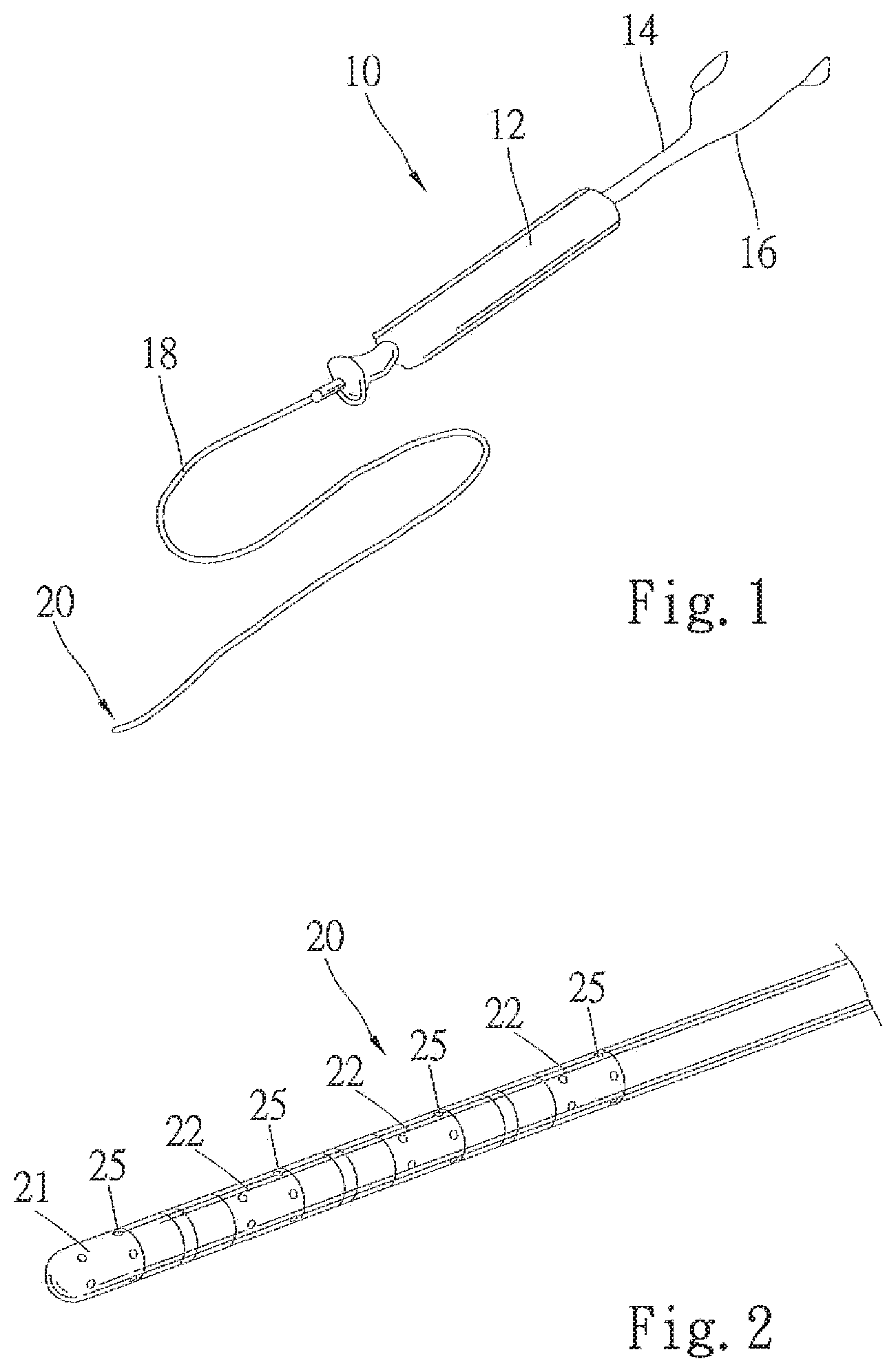
[0019] FIG. 1 is a perspective view of an irrigation catheter system according to an aspect of the inventive subject matter.
[0020] FIG. 2 is a perspective view of the catheter distal region according to an aspect of the inventive subject matter.
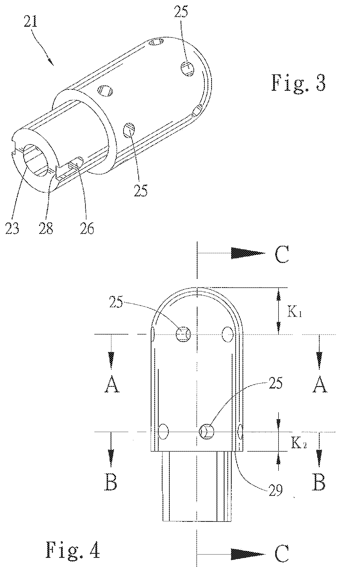
[0021] FIG. 3 is a perspective view of the catheter tip according to an aspect of the inventive subject matter.
[0022] FIG. 4 is a side view of the catheter tip according to an aspect of the inventive subject matter.
[0023] FIG. 4A is a cross sectional view of the catheter tip of FIG. 4 at line A-A, according to an aspect of the inventive subject matter.
[0024] FIG. 4B is a cross sectional view of the catheter tip of FIG. 4 at line B-B, according to an aspect of the inventive subject matter.
[0025] FIG. 5 is a longitudinal cross sectional view of the catheter tip of FIG. 4 at line C-C, according to an aspect of the inventive subject matter.
[0026] FIG. 6 is a longitudinal cross section view of a catheter tip illustrating varied lumen diameter, according to an aspect of the inventive subject matter.
[0027] FIG. 7 is a longitudinal cross section view of a catheter tip illustrating varied lumen diameter, according to an aspect of the inventive subject matter.
[0028] FIG. 8 is a longitudinal cross section view of a catheter distal section illustrating an embodiment having multiple lumens for fluid delivery, according to an aspect of the inventive subject matter.
[0029] FIG. 9 is a longitudinal cross section view of a catheter distal section illustrating an embodiment having multiple lumens for fluid delivery, according to an aspect of the inventive subject matter.
[0030] FIG. 10 is a diagrammatic illustration of side channel configuration, according to an aspect of the inventive subject matter.
[0031] FIG. 11 is a diagrammatic illustration of side channel configuration, according to an aspect of the inventive subject matter.
[0032] FIG. 12 is a diagrammatic illustration of side channel configuration, according to an aspect of the inventive subject matter.
[0033] FIG. 13 is a diagrammatic illustration of side channel configuration, according to an aspect of the inventive subject matter.
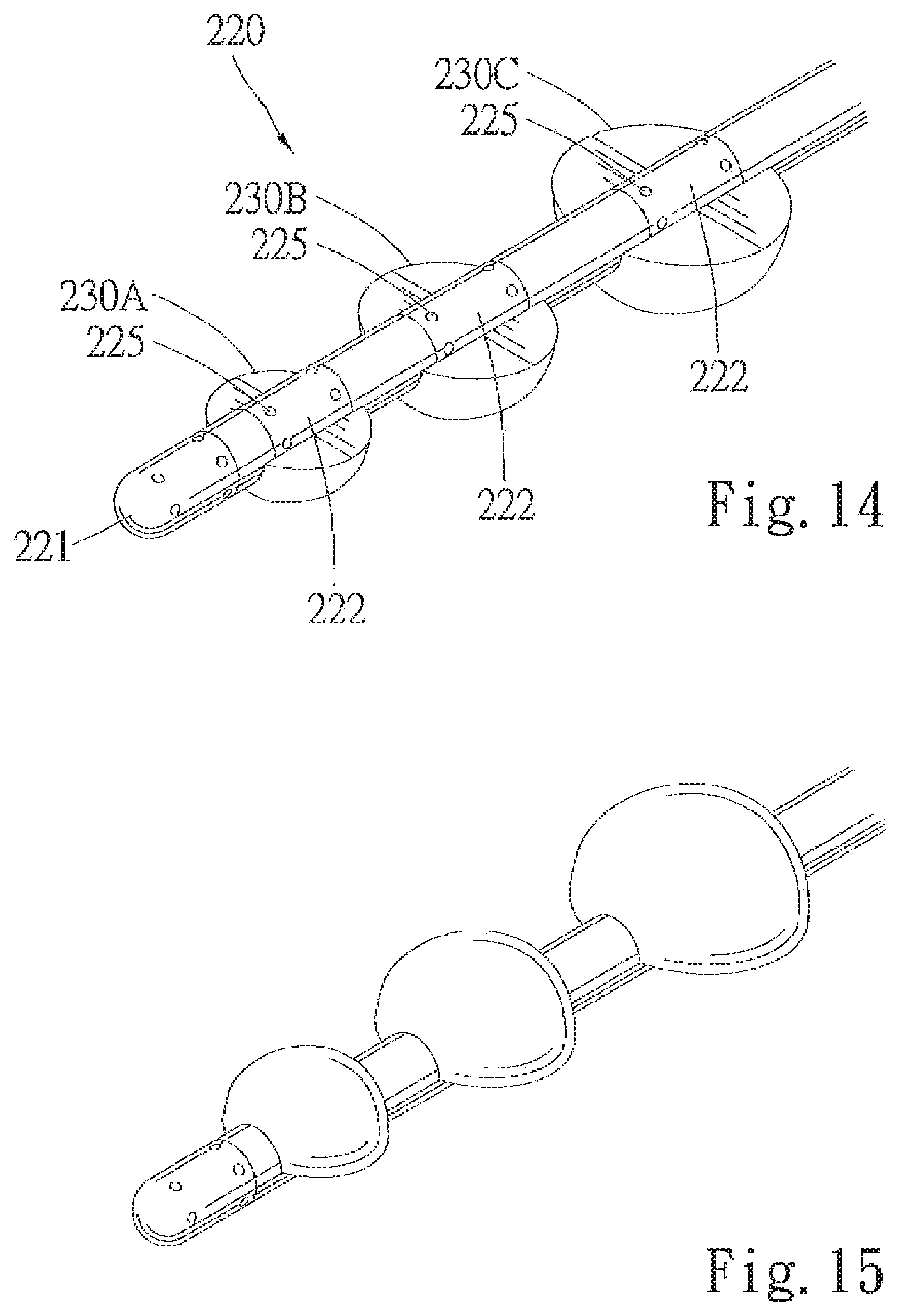
[0034] FIG. 14 is a perspective top view of the catheter distal region having inflatable balloons fully inflated, according to an aspect of the inventive subject matter.
[0035] FIG. 15 is a perspective bottom view of the catheter distal region having inflatable balloons fully inflated, according to an aspect of the inventive subject matter.
[0036] FIG. 16 is a top view of the catheter distal region having inflatable balloons fully inflated, according to an aspect of the inventive subject matter.
[0037] FIG. 17 is a crossectional view of the catheter distal region of FIG. 16 at line E-E, according to an aspect of the inventive subject matter.
DETAILED DESCRIPTION
[0038] The invention and its various embodiments can now be better understood by turning to the following detailed description of the preferred embodiments, which are presented as illustrated examples of the invention defined in the claims. It is expressly understood that the invention as defined by the claims may be broader than the illustrated embodiments described below.
[0039] Many alterations and modifications may be made by those having ordinary skill in the art without departing from the spirit and scope of the invention. Therefore, it must be understood that the illustrated embodiment has been set forth only for the purposes of example and that it should not be taken as limiting the invention as defined by the following claims. For example, notwithstanding the fact that the elements of a claim are set forth below in a certain combination, it must be expressly understood that the invention includes other combinations of fewer, more or different elements, which are disclosed herein even when not initially claimed in such combinations.
[0040] The words used in this specification to describe the invention and its various embodiments are to be understood not only m the sense of their commonly defined meanings, but to include by special definition in this specification structure, material or acts beyond the scope of the commonly defined meanings. Thus if an element can be understood in the context of this specification as including more than one meaning, then its use in a claim must be understood as being generic to all possible meanings supported by the specification and by the word itself.
[0041] The definitions of the words or elements of the following claims therefore include not only the combination of elements which are literally set forth, but all equivalent structure, material or acts for performing substantially the same function in substantially the same way to obtain substantially the same result. In this sense it is therefore contemplated that an equivalent substitution of two or more elements may be made for any one of the elements in the claims below or that a single element may be substituted for two or more elements in a claim. Although elements may be described above as acting in certain combinations and even initially claimed as such, it is to be expressly understood that one or more elements from a claimed combination can in some cases be excised from the combination and that the claimed combination may be directed to a subcombination or variation of a subcombination.
[0042] As used herein, the term "duct" is synonymous with "side channel", both are used herein to describe fluid delivery paths branching off of the main lumen of the catheter.
[0043] Referring now to FIG. 1, which illustrates a catheter system 10, having control unit body 12, tubing sets 14 and 16, and an elongated catheter body 18 with distal region 20. Tubing sets 14 and 16 can be connected to any suitable known devices in the art such as monitor/display, RF generator, signal processor, fluid pump, etc. The preferred system 10 can also use temperature sensor and mapping tool such as those described in U.S. Pat. No. 6,217,573, incorporated herein by reference in its entirety.
[0044] In FIG. 2, catheter distal region 20 has bands of electrodes 22 positioned spaced apart in different longitudinal sections. Each band of electrodes 22 has elution holes 25 located in the same longitudinal sections. At the terminal end is catheter tip 21, also having electrodes. Catheter tip 21 can be manufactured separately and attached to the rest of the elongated catheter body.
[0045] The contemplated catheter tip 21 can be made of suitable biocompatible materials to conduct RF energy and to withstand temperature extreme, such materials include natural and synthetic polymers, various metals and metal alloys, naturally occurring materials, textile fibers, glass and ceramic materials, sol-gel materials, and all reasonable combinations thereof. More preferably, the catheter tip 21 is made of 90% platinum with 10% iridium.
[0046] FIG. 3 shows one preferred embodiment of the catheter tip 21, having a through hole 26 and groove 28. Hole 26 and groove 28 are used to help attaching the catheter tip 21 to the catheter body 18. Catheter body 18 has corresponding structures to matingly couple to the groove 28 and hole 26.
[0047] FIG. 4 is a side view of the catheter tip 21. Preferred embodiments of the catheter tip 21 have two rows of elution holes 25. In this figure, line A-A represents the first row of elution holes, and line B-B represents the second row of elution holes. The terminal end of the tip can be in any configuration, and is preferably spherical. The distance K1 between the most distal tip of the spherical end to the canter of the fast row of elution holes is preferably 0.039 inches. The distance K2 between edge 29 to the center of the second row of elution holes is preferably 0.020 inches. The diameter of both rows of elution holes are preferably 0.016 inches. As for arrangement of electrodes, mapping devices and sensors, these can be referenced from known ablation catheters such as U.S. Pat. No. 6,611,699 issued to Messing, all of which is hereby incorporated by reference in its entirety.
[0048] The number and configuration of elution holes 25 depends on the intended use of the catheter. For example, FIG. 4 shows a configuration where six elution holes 25 in each of the two rows. Each elution hole 25 is fluidly connected with main lumen 23 via ducts 24. Referring to FIGS. 4A and 4B, this configuration provides six ducts 24 radially spread out and spaced evenly from each other in substantially the same degree of angle. This configuration allows all around irrigation and cooling. In comparing FIGS. 4A and 4B, the two rows of elution holes are offset by about 15 degrees. By doing so, the offset rows of elation holes provide more evenly distributed irrigation. It is also contemplated that these two rows may be offset by between 15-45 degrees, or more preferably, by about 30 degrees.
[0049] FIG. 5 provides preferred dimensions of the various elements in the catheter tip 21. In a preferred embodiment, the diameter D1 of the distal portion of the main lumen is about 0.019 inches, and the proximal portion of the lumen, after the tapered flow constrictor 27, has a diameter D2 of about 0.028 inches. The diameter D3 of the main lumen at the neck portion of the catheter tip 21 is about 0.034 inches. In other preferred embodiments, the diameter of main lumen ranges from about 0.005 inch to about 0.045 inch, and wherein the tapered section decreases the diameter by about 5% to about 40% comparing the two diameters immediately adjacent the tapered section.
[0050] The terminal end of the main lumen ends in a flat cone shape, and the distance L1 from the edge of the flat cone to the proximal end of the neck portion is about 0.194 inches. And distance L2 from the tip of the spherical end to the edge 29 is about 0.158 inches. The distance L3 of the neck from the end of the neck to the edge 29 as about 0.065 inches. The distance L4 from the edge of the flat cone to the terminal tip of the sphere is about 0.030 inches. Distance L5 is measured from the larger edge of the tapered flow constrictor 27 to the end of neck, and it is about 0.135 inches.
[0051] FIGS. 6 and 7 illustrate different possible configurations of the flow constrictor 27. The idea of a flow constrictor 27 is to limit or constrict the volume of fluid as the fluid passes toward the distal end of the catheter tip. By decreasing the main lumen 23 diameter using a flow constrictor 27 located substantially equidistance from the first row and from the second row, as shown in FIG. 6, the volume of fluid reaching the first row of elution holes 25 is effectively decreased. A preferred goal is to cause fluid output in the first row of elution holes 25 to be substantially the same volume as the fluid output in the second row. Or more preferably, that all rows of the elution holes 25 that are disposed along the length of electrode region have substantially the same outflow rate. Without a flow constrictor 27, the irrigation system will have an imbalanced outflow pattern where more fluid outflow occurs at the first row. A number of factors are involved in designing an irrigation system with even distribution rate along all of the elution holes. Some of these factors include: size of lumen diameter, percentage differences in diameter decrease, distance between adjacent rows of ducts, diameter of ducts, tilt angle (if any) of the ducts relative to the main lumen. As those of ordinary skill in the art will recognize, the irrigation path described may readily be modified as dictated by the functional needs of particular applications. For example, in some medical applications more irrigation may be desired in the proximal end. One skilled in the art would adjust any one or more of the above factors to create an irrigation system to provide more output flow in the proximal region.
[0052] In some preferred embodiments, the ducts 25 have walls with spiral grooves, influencing flow pattern of the fluid flowing through the ducts 25. With such spiral grooves, the fluid comes out of elution holes 25 with an outwardly spraying walls. This spraying pattern tends to minimize direct impact of the fluid on vessel walls. The spiral grooves can be formed by using appropriate drill bit. The duct wall can have other irregular patterns to create other outflow patterns.
[0053] In FIG. 7, the flow constrictor 27 is a gradual taper that gradually decreases the main lumen diameter, as opposed to a relatively more abrupt taper seen in FIG. 6. Ether abrupt taper or gradual taper, both are preferred over straight angle drop in diameter, because a straight angle drop in diameter can create undesirable eddy currents in the main lumen.
[0054] FIGS. 8, 9, 10 show yet other preferred embodiments of the present invention. These embodiments have two separate lumens 123A, 123B, with each lumen supplying fluid to corresponding rows of ducts 124. These embodiments are less preferred because multiple lumens take up precious cross sectional space in catheter body 118. However, one skilled in the art will recognize that even distribution of fluid can be achieved by having separate fluid delivery lumens for separate rows of conduct, each lumen precisely pressure and volume flow controlled.
[0055] As will be illustrated in connection with FIGS. 10-13, the irrigation system can be advantageously enhanced by arranging the angle of the ducts 24 relative to the main lumen 23. Flow constrictor is omitted from these figures but one skilled in the art would immediately appreciate that flow constrict is required depending on the type of flow output desired. Preferably, a longitudinal axis of each of the plurality of duct 24 and the longitudinal axis of the main lumen are formed at between 35 to 90 degree angles, even more preferably, they are angled at between 45 to 90 degree angles, most preferably, at between 80 to 90 degree angles. In FIG. 10, the ducts 24 are substantially perpendicular to the main lumen 23. In FIG. 11, all of the ducts 24 are tilted towards the distal end, creating a general flow towards the front. In FIG. 12, all of the ducts 24 are tilted towards the proximal end, creating a general flow towards the back. In FIG. 13, a mixture of all three types is provided, creating a general flow away from the ablation area.
[0056] In FIG. 14-17, three inflatable balloons 230A, 230B, 230C can be optionally provided to the electrode catheter as discussed above. Alternatively, this can be a balloon catheter with optional electrodes for ablation. The balloons 230 help navigate and position the electrode 222 to the targeted ablation site. As discussed earlier in other preferred embodiments, elution holes 225 are provided for irrigation purposes, and the catheter has a catheter tip 221. The catheter is first inserted into the patient while the balloon 230 is deflated. Once the user finds the targeted ablation location, the balloon 230 inflates, pushing the electrode side 222 of the catheter region against or closer to the ablation area. As opposed to electrodes described above, these embodiments have electrodes 222 on only the top side of the catheter distal portion. The underside has inflatable balloons 230.
[0057] Contemplated device can have just a single balloon 230, or a plurality of balloons 230. Where a plurality of balloons 230 are provided, the balloon can be of the same size and shape, or alternatively, each balloon 230 can have a distinct shape and size. The preferred embodiment has three balloons 230A, 230B, 230C, with the smallest one at the distal end, and the largest one on the proximal end. This configuration facilitates manipulation of the catheter in a funnel-shaped vessel. When in a funnel-shaped vessel closely corresponds to the shape of the balloon catheter distal region when inflated, the balloon catheter in FIGS. 14-17 can more fittingly secure itself and position electrode to the ablation region. Preferred balloons are half-dome shaped, and have a cross-sectional shape resembling a half circle. Also contemplated configuration is having at least one inflatable balloon, where at least one balloon has an inflated shaped that resembles a longitudinally-dissected cone, or half-cone. The idea is to have one balloon, or a plurality of balloons, where the single balloon or the group of balloons has together an overall general shape that corresponds to the funnel-shaped vessel. This overall general shape can be a longitudinally dissected cone shape, a longitudinally dissected oval (egg-like) shape where a distal end is smaller than the proximal end, or any other shapes where the cross-sectional area is smaller at the distal portion of the overall shape than at its proximal portion. The preferred device uses typical controlling parts and other related configuration for using and positioning the balloon 230, such as those disclosed in U.S. Pat. Nos. 7,137,395 and 6,780,183, all of which are hereby incorporated by reference in their entirety.
[0058] Balloon catheter devices are well known, therefore, general features (e.g. size, shape, materials) of the balloon 230 may be in accordance with conventional balloons. In a preferred embodiment, the balloon 230 is made of flexible medical-grade silicone rubber. Alternatively, the balloon 230 may be made of other biocompatible and distendable materials, such as polyethylene terepthalate (PET).
[0059] While the various embodiments of the irrigation system is herein disclosed as suitable for ablation catheters that perform tissue ablation, and the fluid being suitable cooling fluid such as saline, the same uniform distribution concept can be applied to drug delivery catheters desiring to delivery therapeutic fluid at a uniform rate among the many delivery bores on the catheter distal region. Thus, specific embodiments and applications of multi-electrode irrigated catheter with balloons have been disclosed. It should be apparent, however, to those skilled in the art that many more modifications besides those already described are possible without departing from the inventive concepts herein. The inventive subject matter, therefore, is not to be restricted except in the spirit of the appended claims. Moreover, in interpreting both the specification and the claims, all terms should be interpreted in the broadest possible manner consistent with the context. In particular, the terms "comprises" and "comprising" should be interpreted as referring to elements, components, or steps in a non-exclusive manner, indicating that the referenced elements, components, or steps may be present, or utilized, or combined with other elements, components, or steps that are not expressly referenced. Insubstantial changes from the claimed subject matter as viewed by a person with ordinary skill in the art, now known or later devised, are expressly contemplated as being equivalent within the scope of the claims. Therefore, obvious substitutions now or later known to one with ordinary skill in the an are defined to be within the scope of the defined elements. The claims are thus to be understood to include what is specifically illustrated and described above, what is conceptually equivalent, what can be obviously substituted and also what essentially incorporates the essential idea of the invention. In addition, where the specification and claims refer to at least one of something selected from the group consisting of A, B, C . . . and N, the text should be interpreted as requiring only one element from the group, not A plus N, or B plus N, etc.
* * * * *
D00000
D00001
D00002
D00003
D00004
D00005
D00006
D00007
D00008
XML
uspto.report is an independent third-party trademark research tool that is not affiliated, endorsed, or sponsored by the United States Patent and Trademark Office (USPTO) or any other governmental organization. The information provided by uspto.report is based on publicly available data at the time of writing and is intended for informational purposes only.
While we strive to provide accurate and up-to-date information, we do not guarantee the accuracy, completeness, reliability, or suitability of the information displayed on this site. The use of this site is at your own risk. Any reliance you place on such information is therefore strictly at your own risk.
All official trademark data, including owner information, should be verified by visiting the official USPTO website at www.uspto.gov. This site is not intended to replace professional legal advice and should not be used as a substitute for consulting with a legal professional who is knowledgeable about trademark law.