Warming Unit For Eyelash Curler
CAMPBELL; CLAY ; et al.
U.S. patent application number 16/269366 was filed with the patent office on 2020-02-06 for warming unit for eyelash curler. The applicant listed for this patent is CLAY CAMPBELL, MICHAEL WOODFORD FREITAS. Invention is credited to CLAY CAMPBELL, MICHAEL WOODFORD FREITAS.
| Application Number | 20200037724 16/269366 |
| Document ID | / |
| Family ID | 69229482 |
| Filed Date | 2020-02-06 |


| United States Patent Application | 20200037724 |
| Kind Code | A1 |
| CAMPBELL; CLAY ; et al. | February 6, 2020 |
WARMING UNIT FOR EYELASH CURLER
Abstract
A warming unit includes a body and a heating unit, to work in communication with an eyelash curler to impart a transference of thermal energy to the eyelash curler for the purpose of transferring some of the thermal energy to an eyelash to assist in curling the eyelash. The body has a channel. The channel extends between sides of the body and passes there through. The heating unit is in communication with the body. The heating unit has a heat plate configured to receive electrical energy. The heating unit being partially within the channel. A tang may be included and extend away from the body to form a gap between itself and the heating unit. The eyelash curler is compress therebetween within the gap so as to locate the pad of the eyelash curler against a portion of the heating unit.
| Inventors: | CAMPBELL; CLAY; (ARLINGTON, US) ; FREITAS; MICHAEL WOODFORD; (Plano, TX) | ||||||||||
| Applicant: |
|
||||||||||
|---|---|---|---|---|---|---|---|---|---|---|---|
| Family ID: | 69229482 | ||||||||||
| Appl. No.: | 16/269366 | ||||||||||
| Filed: | February 6, 2019 |
Related U.S. Patent Documents
| Application Number | Filing Date | Patent Number | ||
|---|---|---|---|---|
| 62713728 | Aug 2, 2018 | |||
| Current U.S. Class: | 1/1 |
| Current CPC Class: | A45D 2/48 20130101; A45D 4/16 20130101 |
| International Class: | A45D 4/16 20060101 A45D004/16; A45D 2/48 20060101 A45D002/48 |
Claims
1. A warming unit for heating a pad on an eyelash curler, comprising: a body having a channel; a heating unit in communication with the body, the heating unit including a heat plate configured to receive electrical energy; wherein the channel extends between sides of the body and passes there through, the heating unit being partially within the channel.
2. The unit of claim 1, wherein the channel is formed to the shape of an eyelash curler.
3. The unit of claim 1, wherein the heating unit is at least partially above the channel.
4. The unit of claim 1, further comprising: a tang above a portion of the heating unit, the tang extending from the body outside of the channel.
5. The unit of claim 4, wherein a gap is formed between the tang and the heating unit.
6. The unit of claim 5, wherein the gap and the channel are configured to accept the eyelash curler.
7. The unit of claim 1, wherein the heating unit includes a heat plate for imparting thermal energy to the pad.
8. The unit of claim 7, wherein the temperature of the heat plate is between 150 deg F. and 220 deg F.
9. The unit of claim 7, wherein the heating unit includes a circuit board, the circuit board has an air gap separating a portion of itself from neighboring components in the heating unit, the air gap serves to minimize the transfer of thermal energy to the neighboring components away from the heat plate, such that the heat plate is able to reach a desired temperature with less energy and in a quicker time.
10. The unit of claim 1, further comprising: a port configured to permit the transfer of electrical energy to the heating unit.
11. The unit of claim 10, wherein the port is a USB port.
12. The unit of claim 10, wherein the port includes the ability to regulate the temperature of the pad.
13. The unit of claim 10, wherein the port is configured to turn the heating unit on and off.
14. The unit of claim 1, further comprising: an eyelash curler having a pad on a first member, the pad being located on a side facing a second member, the first member configured to selectively translate toward the second member.
15. The unit of claim 14, wherein the pad includes at least one of a thermally conductive filler, a carbon additive, and a binder so as to increase the thermal properties of the pad.
16. A method of using a warming unit for heating a pad of an eyelash curler, comprising: obtaining a warming unit according to claim 1; locating a first member of the eyelash curler adjacent the heating unit; locating a second member of the eyelash curler adjacent an opposite side of the heating unit as that of the first member, such that the heating unit extends between the first and second members; and inducing an electrical current to impart thermal energy to a heat plate in the heating unit, the heat plate in contact with the pad of the eyelash curler, the pad on the first member.
17. The method of claim 16, wherein the heating unit includes a circuit board adjacent to a surface of the heat plate, the circuit board including an air gap to minimize the transfer of thermal energy away from the heat plate.
18. The method of claim 16, wherein the first member is compressed between the heating unit and a tang, the tang extending out from the body.
19. The method of claim 16, wherein the heating unit extends from the body into the channel.
Description
CLAIM OF PRIORITY
[0001] This application claims the benefit of U.S. Provisional Application No. 62/713,728, filed 2 Aug. 2018. The information contained therein is hereby incorporated by reference.
BACKGROUND
1. Field of the Invention
[0002] The present application relates generally to an electronic warming device, and in particular to a warming unit for an eyelash curler used in the cosmetic industry.
2. Description of Related Art
[0003] Various techniques and practices have been incorporated over time to enhance the beauty of a woman. In the 1800's the idea of lengthening eyelashes gained ground. By the late 1880's practices such as cutting the corners off the eyelashes to "inspire growth" were being done. Other practices including coating the eyelashes with walnut leaves and water to help them stand out and appear longer. Even what would appear extreme today, the practice of sewing hair onto the eyelids to create fake eyelashes was performed in Paris. Over time this process developed from an initial weaving practice in the early 1900's to artificial eyelashes in more recent times.
[0004] Some women prefer not to use artificial eyelashes and prefer to use their own. The cosmetic industry has developed ways to enhance the eyelash. Examples include the use of mascara that is applied with a brush/comb. Various curvatures in the brush and the mascara are said to enhance the natural look of the eyelashes and help give them length and stunning appearance. Another tool developed is the eyelash curler. The curler clamps down on the eyelashes and helps to induce a temporary curvature in the eyelashes. This is to help make the eyelashes more stunning.
[0005] Despite such advancements and progress in the area of eyelashes, shortcomings remain. Artificial eyelashes are cumbersome to use and involve using an adhesive of some type to adhere the artificial hairs to the eyelid. Use of these can result in eye infections and allergic reactions if they are not used properly. With the more natural methods of using a mascara and a curler, these steps tend not to last a long time. Mascara can wear off and any pressing done tends to lose any curling effect if any ever took shape.
[0006] A new method and system is needed that allows for a natural method to create a longer lasting curl in the eyelashes without synthetic hairs and adhesives.
SUMMARY OF THE INVENTION
[0007] It is an object of the present application to provide a warming unit to work in communication with an eyelash curler and be able to impart a transference of thermal energy to a portion of the eyelash curler for the subsequent purpose of transferring some of the thermal energy to an eyelash to assist in curling the eyelash.
[0008] In one embodiment, the warming unit includes a body having a channel. The channel extends between sides of the body and passes there through. A heating unit is also included and is in communication with the body. The heating unit has a heat plate configured to receive electrical energy. The heating unit being partially within the channel.
[0009] It is an object of the present application to present a warming unit that locates the heating unit at least partially above the channel. Furthermore, a tang may extend away from the body to form a gap between itself and the heating unit. The eyelash curler is compress therebetween within the gap so as to locate the pad of the eyelash curler against a portion of the heating unit.
[0010] Furthermore, it is an object of the present application to utilize a heat plate within the heating unit for imparting thermal energy to the pad of the eyelash curler. The temperature of the heat plate is between 150 deg F. and 220 deg F.
[0011] Another object is to facilitate the heating of the heat plate with less electrical energy such that a smaller draw of current is needed, thereby enabling a wider range of connectors and ports. The heating unit includes a circuit board that has an air gap separating a portion of itself from neighboring components in the heating unit. The air gap serves to minimize the transfer of thermal energy to the neighboring components away from the heat plate, such that the heat plate is able to reach a desired temperature with less energy and in a quicker time.
[0012] An electrical port may be a USB port in one embodiment. Furthermore, the port may include the ability to regulate the temperature of the pad and turn the heating unit on and off. Ultimately the invention may take many embodiments. In these ways, this assembly overcomes the disadvantages inherent in the prior art.
[0013] The more important features of the assembly have thus been outlined in order that the more detailed description that follows may be better understood and to ensure that the present contribution to the art is appreciated. Additional features of the system will be described hereinafter and will form the subject matter of the claims that follow.
[0014] Many objects of the present assembly will appear from the following description and appended claims, reference being made to the accompanying drawings forming a part of this specification wherein like reference characters designate corresponding parts in the several views.
[0015] Before explaining at least one embodiment of the system in detail, it is to be understood that the assembly is not limited in its application to the details of construction and the arrangements of the components set forth in the following description or illustrated in the drawings. The assembly is capable of other embodiments and of being practiced and carried out in various ways. Also it is to be understood that the phraseology and terminology employed herein are for the purpose of description and should not be regarded as limiting.
[0016] As such, those skilled in the art will appreciate that the conception, upon which this disclosure is based, may readily be utilized as a basis for the designing of other structures, methods and systems for carrying out the various purposes of the present system. It is important, therefore, that the claims be regarded as including such equivalent constructions insofar as they do not depart from the spirit and scope of the present system.
DESCRIPTION OF THE DRAWINGS
[0017] The novel features believed characteristic of the application are set forth in the appended claims. However, the application itself, as well as a preferred mode of use, and further objectives and advantages thereof, will best be understood by reference to the following detailed description when read in conjunction with the accompanying drawings, wherein:
[0018] FIG. 1 is a front perspective view of a warming unit for eyelash curler according to an embodiment of the present application.
[0019] FIG. 2 is a rear perspective view of the warming unit for eyelash curler of FIG. 1.
[0020] FIG. 3 is a front view of the warming unit for eyelash curler of FIG. 1.
[0021] FIG. 4 is a rear view of the warming unit for eyelash curler of FIG. 1.
[0022] FIG. 5 is a left view of the warming unit for eyelash curler of FIG. 1.
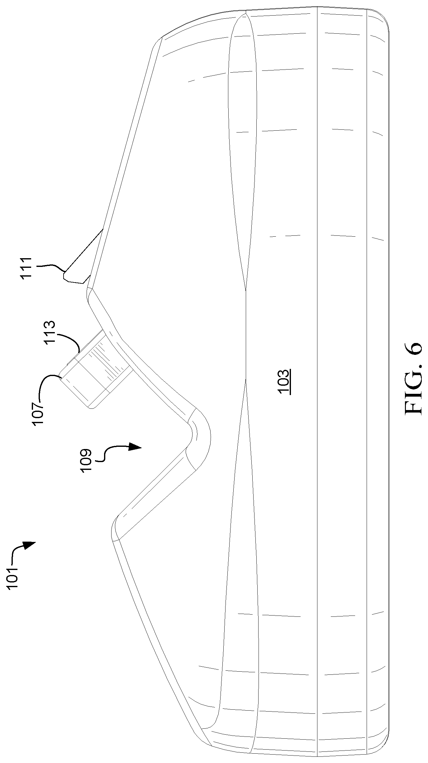
[0023] FIG. 6 is a right view of the warming unit for eyelash curler of FIG. 1.
[0024] FIG. 7 is a top view of the warming unit for eyelash curler of FIG. 1.
[0025] FIG. 8 is a bottom view of the warming unit for eyelash curler of FIG. 1.
[0026] FIG. 9 is a section view of the warming unit for eyelash curler of FIG. 4.
[0027] While the assembly and method of the present application is susceptible to various modifications and alternative forms, specific embodiments thereof have been shown by way of example in the drawings and are herein described in detail. It should be understood, however, that the description herein of specific embodiments is not intended to limit the application to the particular embodiment disclosed, but on the contrary, the intention is to cover all modifications, equivalents, and alternatives falling within the spirit and scope of the process of the present application as defined by the appended claims.
DETAILED DESCRIPTION OF THE PREFERRED EMBODIMENT
[0028] Illustrative embodiments of the preferred embodiment are described below. In the interest of clarity, not all features of an actual implementation are described in this specification. It will of course be appreciated that in the development of any such actual embodiment, numerous implementation-specific decisions must be made to achieve the developer's specific goals, such as compliance with system-related and business-related constraints, which will vary from one implementation to another. Moreover, it will be appreciated that such a development effort might be complex and time-consuming but would nevertheless be a routine undertaking for those of ordinary skill in the art having the benefit of this disclosure.
[0029] In the specification, reference may be made to the spatial relationships between various components and to the spatial orientation of various aspects of components as the devices are depicted in the attached drawings. However, as will be recognized by those skilled in the art after a complete reading of the present application, the devices, members, apparatuses, etc. described herein may be positioned in any desired orientation. Thus, the use of terms to describe a spatial relationship between various components or to describe the spatial orientation of aspects of such components should be understood to describe a relative relationship between the components or a spatial orientation of aspects of such components, respectively, as the assembly described herein may be oriented in any desired direction.
[0030] The assembly and method in accordance with the present application overcomes one or more of the above-discussed problems commonly associated with elevated platforms discussed previously. In particular, the warming unit is a system that operates with an eyelash curler and is configured to induce a heating effect upon a surface of the eyelash curler, such that upon use with the eyelashes, the eyelash curler imparts heat to the lashes and a curling effect is improved. These and other unique features of the assembly are discussed below and illustrated in the accompanying drawings.
[0031] The assembly and method will be understood, both as to its structure and operation, from the accompanying drawings, taken in conjunction with the accompanying description. Several embodiments of the assembly may be presented herein. It should be understood that various components, parts, and features of the different embodiments may be combined together and/or interchanged with one another, all of which are within the scope of the present application, even though not all variations and particular embodiments are shown in the drawings. It should also be understood that the mixing and matching of features, elements, and/or functions between various embodiments is expressly contemplated herein so that one of ordinary skill in the art would appreciate from this disclosure that the features, elements, and/or functions of one embodiment may be incorporated into another embodiment as appropriate, unless otherwise described.
[0032] The assembly and method of the present application is illustrated in the associated drawings. The assembly includes a body that includes a central channel for the acceptance of an eyelash curler. The eyelash curler is seen in particular in FIG. 1. A heating element is located within the channel and is configured to contact a portion of the eyelash curler. An electrical port is located on the side of the body and provides an attachment location for the transfer of electricity to heat the heating element. The heating element may be turned on or off, and in some embodiments may even permit for the control of temperature. Additional features and functions of the device are illustrated and discussed below.
[0033] Referring now to the Figures wherein like reference characters identify corresponding or similar elements in form and function throughout the several views. The following Figures describe the assembly of the present application and its associated features. With reference now to the Figures, an embodiment of the present application is herein described. It should be noted that the articles "a", "an", and "the", as used in this specification, include plural referents unless the content clearly dictates otherwise.
[0034] Referring now to FIGS. 1-9 in the drawings, various views of a warming unit 101 for an eyelash curler 99 is illustrated. Warming unit 101 is configured to provide structural support for the resting of the eyelash curler in an erect position. Furthermore, warming unit 101 is configured to induce a heat transfer of energy to a portion of the eyelash curler 99. The heat is transferred to an eyelash when pressed in eyelash curler 99 to induce a curling effect upon the eyelash.
[0035] In particular with FIG. 1, the eyelash curler 99 is shown in contact with the warming unit 101. Warming unit 101 is configured to provide structural support to hold the eyelash curler in an upright manner. This facilitates ease of grabbing and helps to ensure that the curler is free of debris and contaminants on the counter. Additionally, it allows warming unit 101 to maintain a desired contact with curler 99 along a surface to be heated.
[0036] Warming unit 101 is a small electronic device that is configured to receive electrical power through a port 105. Power may be supplied through any known power source, such as a plug or outlet for example. In some embodiments, warming unit 101 may be powered either partially or wholly through a power supply (i.e. battery). The electrical energy is used to heat a heat plate 113. Heat plate 113 is in close contact with an outer surface of heating unit 107 or actually serves as the outer surface itself. As it is heated, it is adjacent to or in contact with a pad 93 of curler 99. Energy is transferred from heat plate 113 to curler 99.
[0037] Curler 99 is composed of two handles that operate together to translate a first member 97 toward a second member 95. First member 97 translates along the two opposing rails towards second member 95. First member 97 has a pad 93 on the side facing second member 95. In operation, first member 97 slides toward second member 95 and presses eyelashes between pad 93 and second member 95. When the pad 93 is heated, the heat is partially transferred to the eyelashes and helps to induce a curling effect.
[0038] Warming unit 101 includes a body 103, a port 105, and a heating unit 107. Body 103 is configured to at least partially surround heating unit 107 and is shaped to include a channel 109 extending across its width. Channel 109 is configured to cradle and accept second member 95 of the eyelash curler 99 as seen in FIG. 1. It is understood that the overall shape of body 103 is not herein limited to that depicted as other contours may be desirable. For example, depressions are seen along a top surface of body 103 on either side of channel 109. These may be adjusted to other shapes, depths, and contours. Additionally, any surface of body 103 can be configured to receive a surface treatment. Such treatments may include coloring, protection layering like a clear coat for example, grip pads, and so forth. Any textures are possible to improve appearance, comfort, and performance.
[0039] In particular to FIGS. 3-7 in the drawings, various side and front views of warming unit 101 are provided. Channel 109 is sized to accept second member 95 of the eyelash curler 99. Channel 109 includes a contour similar to the eyelash curler to permit relatively flush contact between a portion of the eyelash curler 99 and a side of channel 109. Channel 109 is configured to use interference fit and friction to secure the positioning of the curler 99 and does not necessarily require any additional securing device.
[0040] Heating unit 107 extends inward over a portion of channel 109. When curler 99 is located in channel 109, heating unit 107 extends between first and second members 97 and 95. Heating unit 107 includes a heat plate 113 along an upper surface. Heat plate 113 is exposed through body 103 of heating unit 107 for direct contact with pad 93.
[0041] When second member 95 is within channel 109, second member 95 of the eyelash curler 99 rests along a surface of channel 109 and adjacent heating unit 107. Heating unit 107 is configured to operate with a single surface of channel 109. As seen in the Figures, heating unit 107 may be configured to extend outward into the central portion of channel 109 thereby exposing one or more surfaces that may be heated. These surfaces may contact one or more portions of the eyelash curler 99. In other embodiments, it may be desired to minimize the profile of heating unit 107. In such embodiment it is understood that heating unit 107 may be flush with a surface of channel 109 or may even elect to impart a transference of heat through body 103 wherein heating unit 107 is fully concealed. It is understood that various methods of exposing or transferring heat from heating unit 107 to the eyelash curler is possible.
[0042] As noted previously, heating unit 107 is activated and powered through an electrical power source. It may be composed of a simple resister that emits heat when an electrical current is passed there through. More complex methods of heating are possible and capable for use with warming unit 101. Unit 101 is required to have at least one heating element of any type that is capable of imparting thermal energy onto pad 93 in communication with warming unit 101.
[0043] There are various ways and manners of providing power to heating unit 107. One such way is to rely on an internal power source, such as batteries. These may be interchangeable or even rechargeable when so equipped. Port 105 is located on body 103 and is used to provide a user with operative control of warming unit 101. Port 105 may also include controls to regulate performance of warming unit 101, namely heating unit 107. For example, member 105 may include an on/off switch to regulate power to heating unit 107. Furthermore, an additional control may be provided in member 105 to regulate the amount of power provided to heating unit 107. The idea being that such a control could regulate the temperature or amount of heat energy produced through heating unit 107. This allows a person to adjust the temperature of the eyelash curler to a comfortable and effective level.
[0044] Referring now also to FIG. 8 in the drawings, a bottom view of warming unit 101 is provided. Body 103 has a lower surface. One or more feet or pads are optionally included so as to provide separation between the lower surface and a corresponding counter/surface. The feet/pads may provide increased grip to prevent slippage of body 103 on the surface.
[0045] Referring now also to FIG. 9 in the drawings, a section view of the warming unit 101 is provided as taken from FIG. 4. A more clear view of a tang 111 is shown. Tang 111 extends above, and from, body 103, over a portion of heating unit 107. Additionally, tang 111 extends over a portion of channel 109. A gap 114 is formed between tang 111 and unit 107 configured to accept first member 97 of the eyelash curler 99. In this embodiment, both first member 97 and second member 95 are to be located in channel 109. First member 97 is wedged in gap 114 between tang 111 and heat plate 113 in a manner that compresses pad 93 against heat plate 113. Second member 95 resides in channel 109 and together they are both used to help maintain curler 99 in an upright manner with the handles of the eyelash curler in an accessible position to the user.
[0046] As seen in FIG. 9, heating unit 107 is shown internally. Although the entire body of unit 107 can be referred to as a heating element, it is actually composed of multiple individual members. Unit 107 includes heat plate 113 and a circuit board 115. Heat plate 113 is the device that actually receives the electrical current to heat up and is exposed in the gap on the upper front side of unit 107, adjacent tang 111. Beneath plate 113 is circuit board 115 configured to regulate performance of unit 101. An air gap 117 is formed beneath circuit board 115 to help minimize the transfer of heat energy to other parts of unit 107. This helps to maintain a constant temperature with heat plate 113 and decrease the electrical energy required to get it up to temperature. The air gap also serves to minimize the transfer of thermal energy to the other components away from the heat plate, such that the heat plate is able to reach a desired temperature with less energy and in a quicker time. By including the air gap 117, port 105 may be a USB port wherein minimal electrical current is needed to heat plate 113. It is understood that in combination with or in lieu of air gap 117, unit 107 may include one or more insulating materials. These can be layered adjacent to heat plate 113 and/or circuit board 115 for example.
[0047] In operation, it is advantageous to have pad 93 at an elevated temperature around 150 deg F. to 220 deg F. Pad 93 is typically composed of some elastomeric materials that fail to exhibit good thermal conductivity. Additionally, pad 93 has a poor thermal mass such that when heated to temperatures above 220 deg F. (i.e. 250 deg F.), pad 93 may only feel warm to the touch. Therefore, curler 99 may include a pad 93 that has various thermally conductive fillers, such as powdered metals like Al, Cu, Ag, and Au. Furthermore, carbon in various forms (Powdered, Flakes, Fibers) Boron Nitride, etc. may be included. Obviously, the elastomeric material must have a degree of heat deflection temperatures greater than the maximum use temperatures. Binders may also be incorporated into pad 93 to add strength. It is understood that warming unit 101 may also include curler 99 wherein pad 93 includes any one of thermally conductive fillers, carbon additives, and binders.
[0048] Particular advantages of warming unit 101 include at least the following: (1) the ability to elevate and hold an eyelash curler in an upright manner for ease of use and to maintain cleanliness; (2) a heating unit is provided to selectively heat a portion of the eyelash curler to aid in transferring heat to the eyelashes of the user to aid in maintaining a curl longer; and (3) operative control of the heat plate to regulate performance and temperature.
[0049] The particular embodiments disclosed above are illustrative only, as the application may be modified and practiced in different but equivalent manners apparent to those skilled in the art having the benefit of the teachings herein. It is therefore evident that the particular embodiments disclosed above may be altered or modified, and all such variations are considered within the scope and spirit of the application. Accordingly, the protection sought herein is as set forth in the description. It is apparent that an application with significant advantages has been described and illustrated. Although the present application is shown in a limited number of forms, it is not limited to just these forms, but is amenable to various changes and modifications without departing from the spirit thereof.
* * * * *
D00000
D00001
D00002
D00003
D00004
D00005
D00006
D00007
D00008
XML
uspto.report is an independent third-party trademark research tool that is not affiliated, endorsed, or sponsored by the United States Patent and Trademark Office (USPTO) or any other governmental organization. The information provided by uspto.report is based on publicly available data at the time of writing and is intended for informational purposes only.
While we strive to provide accurate and up-to-date information, we do not guarantee the accuracy, completeness, reliability, or suitability of the information displayed on this site. The use of this site is at your own risk. Any reliance you place on such information is therefore strictly at your own risk.
All official trademark data, including owner information, should be verified by visiting the official USPTO website at www.uspto.gov. This site is not intended to replace professional legal advice and should not be used as a substitute for consulting with a legal professional who is knowledgeable about trademark law.