Heat Exchanger
Kent; Scott E. ; et al.
U.S. patent application number 16/045197 was filed with the patent office on 2020-01-30 for heat exchanger. The applicant listed for this patent is MAHLE International GmbH. Invention is credited to Scott E. Kent, Kurt R. Mittlefehldt.
| Application Number | 20200033073 16/045197 |
| Document ID | / |
| Family ID | 69149121 |
| Filed Date | 2020-01-30 |

| United States Patent Application | 20200033073 |
| Kind Code | A1 |
| Kent; Scott E. ; et al. | January 30, 2020 |
HEAT EXCHANGER
Abstract
A heat exchanger (1) includes a first manifold (2) and a second manifold (3) fluidically connected by at least one tube (4) with at least one brazed joint between one manifold (2,3) and the tube (4). The brazed joint is made of braze material. The first manifold (2) and the second manifold (3) are formed from non-braze materials with a higher melting point than the braze material. The non-braze material does not melt during brazing. At least one of the manifolds (2,3) has at least two non-braze material layers.
| Inventors: | Kent; Scott E.; (Albion, NY) ; Mittlefehldt; Kurt R.; (Amherst, NY) | ||||||||||
| Applicant: |
|
||||||||||
|---|---|---|---|---|---|---|---|---|---|---|---|
| Family ID: | 69149121 | ||||||||||
| Appl. No.: | 16/045197 | ||||||||||
| Filed: | July 25, 2018 |
| Current U.S. Class: | 1/1 |
| Current CPC Class: | F28F 2255/06 20130101; F28F 2275/04 20130101; F28F 9/0224 20130101; F01N 2240/02 20130101; F28D 1/0391 20130101; F28D 1/05366 20130101; F28F 19/06 20130101; F28D 2021/008 20130101; F28F 21/089 20130101; F28F 1/126 20130101; F28F 9/18 20130101; F28F 9/182 20130101 |
| International Class: | F28F 9/18 20060101 F28F009/18; F28F 9/02 20060101 F28F009/02 |
Claims
1. A heat exchanger (1) comprising: a first manifold (2); a second manifold (3); at least one tube (4) with a tube profile (5) fluidically connecting the first manifold and the second manifold, the tube profile (5) having at least one channel (6) for a flow of a fluid between the first manifold (2) and the second manifold (3); and at least one brazed joint between one of the first and second manifolds (2,3) and the tube (4), the brazed joint being made of braze material; wherein the first manifold (2) and the second manifold (3) are formed from non-braze materials with a higher melting point than the braze material, the non-braze material being configured not to melt during brazing; and wherein at least one of the first and second manifolds (2,3) has at least two non-braze material layers.
2. The heat exchanger according to claim 1, wherein the at least one of the first and second manifolds (2,3) with the at least two non-braze material layers has an inner non-braze material layer (7) and an outer non-braze material layer (8), where the outer non-braze material layer (8) is more anodic than the inner non-braze material layer (7).
3. The heat exchanger according to claim 2, wherein the at least one of the first and second manifolds (2,3) with the at least two non-braze material layers is formed by roll forming and welding.
4. The heat exchanger according to claim 2, wherein the at least one of the first and second manifolds (2,3) with the at least two non-braze material layers is formed by coextrusion.
5. The heat exchanger according to claim 2, wherein the at least one of the first and second manifolds (2,3) with the at least two non-braze material layers is formed by coextrusion followed by drawing.
6. The heat exchanger according to claim 1, wherein the at least one of the first and second manifolds (2,3) with the at least two non-braze material layers has an inner non-braze material layer (7) and an outer non-braze material layer (8), where the outer non-braze material layer (8) has an equal or higher strength than the inner non-braze material layer (7).
7. The heat exchanger according to claim 6, wherein the at least one of the first and second manifolds (2,3) with the at least two non-braze material layers is formed by roll forming and welding.
8. The heat exchanger according to claim 6, wherein the at least one of the first and second manifolds (2,3) with the at least two non-braze material layers is formed by coextrusion.
9. The heat exchanger according to claim 6, wherein the at least one of the first and second manifolds (2,3) with the at least two non-braze material layers is formed by coextrusion followed by drawing.
10. A heat exchanger (1) comprising: a first manifold (2); a second manifold (3); at least one tube (4) with a tube profile (5) fluidically connecting the first manifold and the second manifold, the tube profile (5) having at least one channel (6) for a flow of a fluid between the first manifold (2) and the second manifold (3); and at least one brazed joint between one of the first and second manifolds (2,3) and the tube (4), the brazed joint being made of braze material; wherein the first manifold (2) and the second manifold (3) are formed from non-braze materials with a higher melting point than the braze material, the non-braze material being configured not to melt during brazing; and wherein at least one of the first and second manifolds (2,3) is formed from a single strip of a non-braze material by roll forming and welding.
Description
TECHNICAL FIELD
[0001] The present invention relates to a heat exchanger applying to residential, commercial, transport and the automotive market.
BACKGROUND
[0002] Heat exchangers such as radiators and heater cores have used folded tubes for many years, welded tubes were also common. A folded tube is defined as a tube formed partially or completely from strip stock and typically roll formed to a shape which, after brazing, is able to contain a working fluid used for the particular type of heat exchanger for which the tube was intended for. The tube can be formed, typically roll formed, from one or more individual strips of material of heat conductive material. The heat conductive material is shaped in such a way that the tube body has at least one internal channel or formed port for a flow of a fluid. Due to the folding of the heat conductive material, at least one external seam extending in a longitudinal direction of the tube body is created. This seam may have a triangular-shaped or delta-shaped cross-section due to the radius which occurs as the result of forming the material strip. Folded tube use for other heat exchangers including oil coolers, condensers and evaporators is more recent. Prior to folded tube use in condensers primarily extruded tubes were used. For evaporators, flat plate or extruded tubes were the most common tube technologies.
[0003] Regardless of heat exchanger type a heat exchanger, using either extruded tubes or welded tubes or folded tubes, typically comprise a first manifold and a second manifold being spaced apart and fluidically connected by at least one tube. A first fluid flowing from the first manifold to the second manifold through the tube is in thermal contact with interior surfaces of the tube while a second fluid like ambient air is in thermal contact with exterior surfaces of the tube. Typically, such heat exchangers are assembled with a plurality of tubes (folded and/or extruded and/or welded), where two adjacent tubes are spanned by an extended surface such as corrugated fins to increase the available surface area for heat transfer. As long as the two fluids have different temperatures, a heat transfer from the warmer to the colder fluid can be achieved through the tube.
[0004] Such heat exchangers are typically manufactured in two steps. In the first step, the components of the heat exchanger, i.e. at least the manifolds, tubes, and fins are assembled to create a unitary structure. In the second step, the components are joined together by furnace brazing. The brazing process requires a filler or braze material with a lower melting point than the adjoining components of the heat exchanger.
[0005] The type of tube construction influences which parts are designed with braze material and which parts are not. In order to ensure that the heat exchanger can be produced consistently and cost-effectively, the braze material is typically rolled integrally with the base material to the raw material and most frequently on those parts which are rolled sheet products; although coextruded manifolds do exist where the outer material is braze material. When the braze material is applied on the roll formed sheet, it is often referred to as "braze clad". A suitable braze material must have a melt temperature specifically designed to melt at a temperature lower than the primary or parent material such that the structure of the part can be maintained while the braze material melts and flows to form metallurgical bonds once the braze process is complete.
[0006] For extruded tubes, the braze clad is rolled integrally with the base material of the header or of the manifold in the case of a manifold where the manifold cylinder is made from a single part. During the brazing process, the braze cladding of the manifolds melts and creates brazed joints between the manifolds and the extruded tubes.
[0007] For folded tubes, the braze material is typically rolled integrally with the base material as one of the layers of the folded tube roll formed strip stock sheet. Braze material can as well be present on the manifold or header but doing so comes with the risk of causing folded tube erosion.
[0008] Although there is a substantially uniform temperature distribution within the furnace, the folded tubes reach the final temperature more quickly than the heavier manifolds. This results in a temperature gradient along the heat exchanger at least temporarily. During this time, the maximum temperature is reached in the middle of the respective folded tube. Due to this temperature gradient and the capillary effect of the gap of the respective tube body, the liquid braze material flows along the gap of the respective tube body from the manifolds toward the middle of the respective folded tube. While the liquid braze material flows over the surface of the seam of the folded tube, it partially dissolves this surface resulting in an erosion along the folded tube in longitudinal (guttering) as well as transverse (undercutting) direction. Due to this, the structural strength of the folded tube is reduced in the vicinity of such an erosion. This may result in lower pressure resistance to of the fluid flowing along the internal channels or ports of the folded tube. Additionally, the chemical composition and grain structure of the folded tube near such an erosion is changed, potentially making the heat exchanger more susceptible to corrosion.
SUMMARY OF THE INVENTION
[0009] The present application is based on the objective of specifying a heat exchanger with improved corrosion resistance as well as improved structural strength.
[0010] This objective is achieved by using manifolds with at least two non-braze material layers.
[0011] According to one aspect of the present invention, the heat exchanger comprises a first manifold and a second manifold which are fluidically connected by at least one tube. The tube may be a folded tube, welded tube or extruded tube. A folded tube may be created using multi-layer rolled sheet with at least the outer layer being braze clad material. The multi-layer sheet may comprise at least one layer of primary or "core" material. The tube profile may be formed from using at least one strip of the multi-layered composite material by roll forming, where the core material has a higher melting point than the braze clad layer(s). The core material may be aluminium or an aluminium alloy. The braze cladding may be an aluminium-silicon alloy which has lower melting point compared to the core aluminium. With the selection of the amount of silicon in the aluminium-silicon alloy, the melting point and liquidus line of the braze cladding can be adjusted according to the requirements of the manufacturing process
[0012] According to a further aspect, the tube profile may have at least one channel or port for flow of a fluid between the first manifold and the second manifold. The tube profile may be shaped in such a way that the tube profile comprises several internal folds creating webs or ribs which extend substantially along the length of the folded tube. The internal webs or ribs may define a plurality of channels through which the fluid can flow. These internal webs or ribs increase the surface area between the tube and the fluid flowing through the tube improving the heat transfer. In addition, the internal webs or ribs increase the structural strength of the tube.
[0013] According to a further aspect of the present invention, the first manifold and the second manifold are formed from non-braze materials with a higher melting point than the braze material, therefore the non-braze material does not melt during brazing. The term "non-braze materials" includes that the manifolds may be formed from a single non-braze material, a composition of several non-braze materials, a non-braze alloy or a composition of several non-braze alloys. Since at least one manifold has at least two non-braze material layers, where one layer may form a sacrificial layer, the corrosion resistance as well as structural strength of the manifold and thus of the whole heat exchanger is improved.
[0014] During the brazing process, at least one brazed joint between one manifold and the tube is created, with the brazed joint being made of braze material. If a folded tube is used, the braze cladding of the respective folded tube melts and creates a longitudinal braze joint seam closing the seam gap of the respective folded tube. Chemically, the tube clad layer and the outer surface of the tube core material interact to form a sacrificial corrosion layer.
[0015] In an advantageous development of the solution according to the invention, the manifold with at least two non-braze material layers may have an inner non-braze material layer and an outer non-braze material layer, where the outer non-braze material layer is more anodic compared to the inner non-braze material layer and is more corrosion-prone than the inner non-braze material. Since the outer non-braze material layer is more susceptible to corrosion, this layer is sacrificial to the inner non-braze material layer. The outer non-braze material layer protects the inner non-braze material layer (core material) by encouraging the corrosion to move laterally over the sacrificial outer layer as opposed to penetrating the core material. For a certain period of time, corrosion will only affect the outer non-braze layer. Thus, the corrosion resistance of the manifold is improved.
[0016] In a further advantageous aspect of the invention, the manifold with at least two non-braze material layers has an inner non-braze material layer and an outer non-braze material layer, where the outer non-braze material layer has an equal or higher strength than the inner non-braze material layer. Thus, the strength as well as the pressure resistance of the manifold is improved. It is also possible that the outer non-braze material layer is not sufficiently different electro chemically to be sacrificial but still offers a strength improvement over the inner non-braze material layer.
[0017] In an advantageous development of the solution according to the invention, the manifold with at least two non-braze material layers is formed by roll forming and welding. The manifold with at least two non-braze material layers may be formed from a multi-layer composite sheet by roll forming. The manifold may be formed in one piece from multi-layer composite sheet. After performing the roll forming process, a welding procedure may be used to obtain a fluid-impermeable construction of the manifold. The use of at least two non-braze material layers provides a way to produced manifolds with customized properties. Due to the roll forming process, the manifold provides an adequate strength at a given wall thickness. Additionally, high strength alloys may be used having a hardness which is too high to extrude the material. Thus, high strength roll formed alloys provide a hardness which would be impossible to extrude.
[0018] According to further aspects of the invention, the manifold with at least two non-braze material layers may be formed by coextrusion and may be followed by drawing. The manifold may be formed in one piece. The outer non-braze material layer has may be extruded over the inner non-braze material layer. This solution is advantageous if the tools for roll forming are not available, so that initial investment is avoided since there is no need to purchase such tools. The manifold may be single drawn or double drawn providing a higher strength.
[0019] According to yet another aspect of the invention, an innovative heat exchanger comprises a first manifold and a second manifold which are fluidically connected by at least one tube. The tube may be a folded tube, welded tube or extruded tube. A folded tube may be created using multi-layer rolled sheet with at least the outer layer being braze clad material. The multi-layer sheet may comprise at least one layer of primary or "core" material. The tube profile may be formed from using at least one strip of the multi-layered composite material by roll forming, where the core material has a higher melting point than the braze clad layer(s). The core material may be aluminium or an aluminium alloy. The braze cladding may be an aluminium-silicon alloy which has lower melting point compared to the core aluminium. With the selection of the amount of silicon in the aluminium-silicon alloy, the melting point and liquidus line of the braze cladding can be adjusted according to the requirements of the manufacturing process
[0020] The tube profile may have at least one channel or port for flow of a fluid between the first manifold and the second manifold. The tube profile may be shaped in such a way that the tube profile comprises several internal folds creating webs or ribs which extend substantially along the length of the folded tube. The internal webs or ribs may define a plurality of channels through which the fluid can flow. These internal webs or ribs increase the surface area between the tube and the fluid flowing through the tube improving the heat transfer. In addition, the internal webs or ribs increase the structural strength of the tube.
[0021] The first manifold and the second manifold are formed from non-braze materials with a higher melting point than the braze material, therefore the non-braze material does not melt during brazing. The wording non-braze materials means that the manifolds may be formed from a single non-braze material, a composition of several non-braze materials, a non-braze alloy or a composition of several non-braze alloys.
[0022] At least one manifold is formed from a single strip of a non-braze material by roll forming and welding. This manifold may be formed in one piece from single-layer roll formed sheet. After performing the roll forming process, a welding procedure may be used to obtain a fluid-impermeable construction of the manifold. The use of a single strip of a non-braze material provides a simple and cost-effective method of manufacturing the heat exchanger.
[0023] While a single layer sheet will not have the advantage of an additional layer of sacrificial material, the alloy selection for roll formed strip has fewer limitations than that of single extruded material. The control of grain shape of roll formed strip and the ability to vary the chemistry of roll formed strip beyond what would be practically possible to extrude make a one piece rolled strip non-clad manifold an inexpensive solution with high strength and good corrosion resistance. This may not be the highest strength option or the option with the ultimate corrosion resistance, but it is a solution which is still far better than any existing solution.
[0024] Further important features and advantages of the invention emerge from the de-pendent claims, from the drawings and from the associated description of the figures with reference to the drawings.
[0025] Any features mentioned above and described below can be used not only in the respectively stated combination, but also in different combinations or individually without departing from the scope of the present invention.
[0026] Preferred exemplary embodiments of the invention are illustrated in the drawings and are explained in more detail in the description below, wherein the same reference characters refer to identical or similar or functionally identical components.
BRIEF DESCRIPTION OF THE DRAWINGS
[0027] In the drawings,
[0028] FIG. 1 shows a heat exchanger according to the invention,
[0029] FIG. 2 shows a cross-section of a manifold with two non-braze material layers according to the invention,
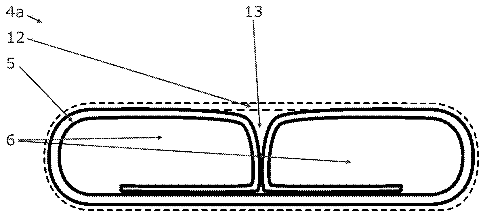
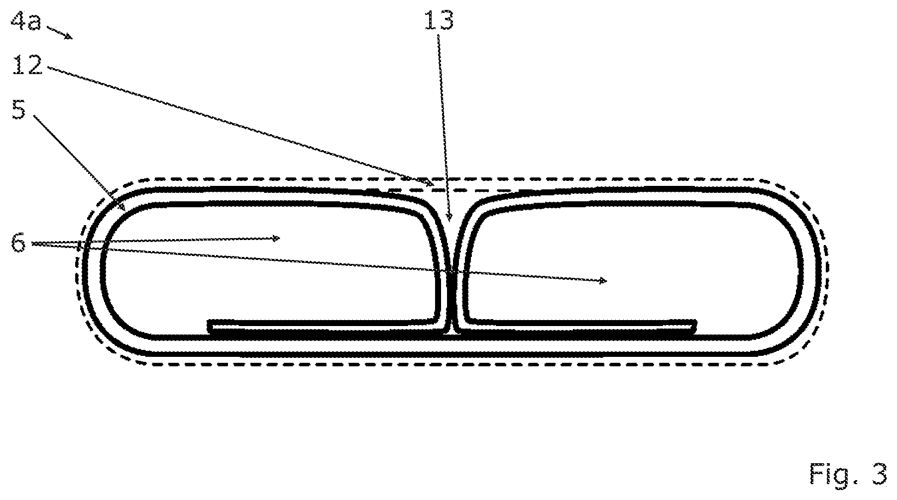
[0030] FIG. 3 shows a cross-section of a folded tube before brazing according to the invention.
[0031] The drawings are schematic representations that are not necessarily drawn to scale, unless expressly mentioned. The drawings are included for illustrative purposes only and are not intended to limit the scope of the present invention.
DETAILED DESCRIPTION OF THE DRAWINGS
[0032] According to FIG. 1, a heat exchanger 1 according to the invention has a first manifold 2 and a second manifold 3 being spaced apart and fluidically connected by at least one tube 4. The heat exchanger 1 comprises a plurality of tubes 4 which are spaced apart. Adjacent tubes 4 are respectively interconnected by a fin arrangement 9 with a corrugated fin in order to increase the available surface area for heat transfer.
[0033] The heat exchanger 1 may be fluidically connected to fluid circuit of a vehicle which is not shown in the figures. This fluid circuit may have least one electrically driven conveying unit for driving a first fluid within the fluid circuit. The fluid circuit may be a part of an HVAC (Heating, Ventilation and Air Conditioning) system of a vehicle.
[0034] The first manifold 2 has an inlet 10 and the second manifold 3 has an outlet 11. The first fluid may flow through the inlet 10 into the heat exchanger 1 and may leave the heat exchanger 1 through the outlet 11.
[0035] The first fluid flowing from the first manifold 2 to the second manifold 3 through the tubes 4 is in thermal contact with interior surfaces of the tubes 4, while a second fluid, such as ambient air, is in thermal contact with exterior surfaces of the tubes 4. Additionally, the second fluid is in contact with the fin arrangements 9. As long as the two fluids have different temperatures, a heat transfer from the warmer to the colder fluid can be achieved through the tubes 4 and fin arrangements 9.
[0036] The first manifold 2, the second manifold 3 and the tube 4 are assembled such that the first manifold 2 and the second manifold 3 are fluidically connected by the tube 4. This assembly is brazed or furnace brazed in order to create brazed joints between the manifolds 2,3 and the tube 4. This provides a cost-efficient and modular production of the heat exchanger.
[0037] FIG. 2 shows a cross-section of a manifold 2 with two non-braze material layers according to the invention. The manifold 2 has a tube-like cross-section with an inner non-braze material layer 7 and an outer non-braze material layer 8. The outer non-braze material layer 8 may have a higher strength than the inner non-braze material layer 7. Additionally, the outer non-braze material layer 8 may be more anodic than the inner non-braze material layer 7. For a certain period of time, corrosion will only affect the outer non-braze layer 8. Thus, the corrosion resistance and the structural strength of the manifold 2 may be improved. The manifold 2 may comprise several non-braze material layers with different material properties in order to meet technical requirements. The manifold 2 shown in FIG. 2 may be manufactured by roll forming or coextrusion.
[0038] FIG. 3 shows a cross-section of a tube 4 before brazing according to the invention. In this case, the tube 4 is a folded tube 4a. The folded tube 4a comprises a tube profile 5 and braze material 12. The first manifold 2, the second manifold 3 and the tube profile 5 are formed from non-braze materials with a higher melting point than the braze material 12.
[0039] The tube profile 5 is formed from a strip of heat conductive material by roll forming. The heat conductive material is shaped in such a way that the tube profile 5 provides two channels 6 for a flow of the first fluid between the first manifold 2 and the second manifold 3. Due to the folding of the heat conductive material, at least one gap 13 extending in a longitudinal direction of the tube profile 5 is created. This gap 13 may have a triangular-shaped or delta-shaped cross-section. The braze material 12 may extend substantially along the length of the folded tube 4a and may enclose the tube profile 5. During a brazing process, the braze material 12 of the respective folded tube 4a melts and creates a longitudinal seam closing the gap 13 of the respective folded tube 4a. Additionally, the braze material 12 creates brazed joints between the first manifold 2 and the second manifold 3 and the respective folded tube 4. Since the liquid braze material fills the gap 13 evenly, a flow of the liquid braze material along the gap 13 in longitudinal direction of the tube profile 5 is avoided. Due to this, an erosion of the respective folded tube 4a is supressed.
[0040] While the above description constitutes the preferred embodiments of the present invention, it will be appreciated that the invention is susceptible to modification, variation and change without departing from the proper scope and fair meaning of the accompanying claims.
* * * * *
D00000
D00001
D00002
XML
uspto.report is an independent third-party trademark research tool that is not affiliated, endorsed, or sponsored by the United States Patent and Trademark Office (USPTO) or any other governmental organization. The information provided by uspto.report is based on publicly available data at the time of writing and is intended for informational purposes only.
While we strive to provide accurate and up-to-date information, we do not guarantee the accuracy, completeness, reliability, or suitability of the information displayed on this site. The use of this site is at your own risk. Any reliance you place on such information is therefore strictly at your own risk.
All official trademark data, including owner information, should be verified by visiting the official USPTO website at www.uspto.gov. This site is not intended to replace professional legal advice and should not be used as a substitute for consulting with a legal professional who is knowledgeable about trademark law.