3d Printed Radiator Core
Barney; Brian ; et al.
U.S. patent application number 16/044937 was filed with the patent office on 2020-01-30 for 3d printed radiator core. The applicant listed for this patent is GLOBAL HEAT TRANSFER ULC. Invention is credited to Brian Barney, Hamid Reza Zareie Rajani, Haoxuan Yan.
| Application Number | 20200033062 16/044937 |
| Document ID | / |
| Family ID | 67441712 |
| Filed Date | 2020-01-30 |


| United States Patent Application | 20200033062 |
| Kind Code | A1 |
| Barney; Brian ; et al. | January 30, 2020 |
3D PRINTED RADIATOR CORE
Abstract
A 3D printed radiator core that includes a first fluid passageway further having a first sidewall; a second sidewall; a top platform; and a bottom platform. There is a second fluid passageway proximate to, but fluidly isolated from, the first fluid passageway. An at least part of the first fluid passageway is defined in lateral cross-section by the top platform having an upward extending ridge.
| Inventors: | Barney; Brian; (Peoria, IL) ; Rajani; Hamid Reza Zareie; (Edmonton, CA) ; Yan; Haoxuan; (Edmonton, CA) | ||||||||||
| Applicant: |
|
||||||||||
|---|---|---|---|---|---|---|---|---|---|---|---|
| Family ID: | 67441712 | ||||||||||
| Appl. No.: | 16/044937 | ||||||||||
| Filed: | July 25, 2018 |
| Current U.S. Class: | 1/1 |
| Current CPC Class: | F28F 1/26 20130101; F28D 1/05383 20130101; F28D 2001/0266 20130101; F28F 1/08 20130101; F28D 1/05366 20130101; F28D 2001/028 20130101; F28F 1/24 20130101 |
| International Class: | F28D 1/053 20060101 F28D001/053 |
Claims
1. A 3D printed radiator core comprising: a first fluid passageway further comprising: a first sidewall; a second sidewall; a top platform; and a bottom platform; a second fluid passageway proximate to, but fluidly isolated from, the first fluid passageway; wherein an at least part of the first fluid passageway is defined in lateral cross-section by the top platform having an upward extending curvilinear ridge, and by the bottom platform having a downward extending curvilinear ridge.
2. The 3D printed radiator core of claim 1, wherein the upward extending curvilinear ridge lies proximately above the downward extending curvilinear ridge on a shared vertical axis.
3. The 3D printed radiator core of claim 2, wherein a crest of the upward extending curvilinear ridge is separated from an another crest of the downward extending curvilinear ridge by a ridge height in the range of 0.25 mm to 3 mm.
4. The 3D printed radiator core of claim 3, wherein the top platform comprises a second upward extending curvilinear ridge, and the bottom platform comprises a second downward extending ridge, and wherein the first sidewall and the second sidewall are separated by a sidewall gap in a range of 5 mm to 9 mm.
5. The 3D printed radiator core of claim 4, wherein in the at least part of the first fluid passageway in lateral cross-section comprises a top half of the first fluid passageway substantially symmetrical to a bottom half of the first fluid passageway.
6. The 3D printed radiator core of claim 4, wherein in the at least part of the first fluid passageway in lateral cross-section comprises a first side half of the first fluid passageway substantially symmetrical to a second side half of the first fluid passageway.
7. The 3D printed radiator core of claim 1, the second fluid passageway further comprising: a first second fluid passageway sidewall; and a second second fluid passageway sidewall, wherein the second fluid passageway is transverse to the first fluid passageway, and wherein an at least part of the second fluid passageway is defined in lateral cross-section by the first second fluid passageway sidewall having at least one curvature.
8. The 3D printed radiator core of claim 7, wherein the upward extending curvilinear ridge extends into the second fluid passageway.
9. The 3D printed radiator core of claim 1, the first fluid passageway further comprising an entry and an exit, wherein the entry and the exit are separated by a length in a range of 70 inches to about 90 inches, and wherein the upward extending curvilinear ridge extends along the length.
10. A 3D printed radiator core comprising: a first fluid passageway further comprising: a first sidewall; a second sidewall; a top platform; and a bottom platform; a second fluid passageway proximate and thermally conductive to, but fluidly isolated from, the first fluid passageway; wherein an at least part of the first fluid passageway is defined in lateral cross-section by the top platform having an upward extending ridge, and by the bottom platform having a downward extending ridge.
11. The 3D printed radiator core of claim 10, wherein the upward extending ridge lies proximately above the downward extending ridge on a shared vertical axis.
12. The 3D printed radiator core of claim 10, wherein an innermost surface of a crest of the upward extending ridge is separated from an another innermost surface of a crest of the downward extending ridge by a ridge height in a range of 0.4 mm to 2.4 mm, and wherein an amplitude of the crest with reference to the top platform is in a range of 0.1 mm to 1.5 mm.
13. The 3D printed radiator core of claim 10, wherein the top platform comprises a second upward extending ridge, and the bottom platform comprises a second downward extending ridge, and wherein the first sidewall and the second sidewall are separated by a sidewall gap in a range of 5 mm to 9 mm, and wherein at least a portion of an innermost surface of the top platform is separated from an another portion of an innermost surface of the bottom platform by a platform height in a range of 0.2 mm to 1 mm.
14. The 3D printed radiator core of claim 13, wherein the at least part of the first fluid passageway in lateral cross-section comprises a top half of the first fluid passageway substantially reflectionally symmetrical to a bottom half of the first fluid passageway.
15. The 3D printed radiator core of claim 10, wherein the at least part of the first fluid passageway in lateral cross-section comprises a first side half of the first fluid passageway substantially reflectionally symmetrical to a second side half of the first fluid passageway.
16. The 3D printed radiator core of claim 15, wherein an at least part of the second fluid passageway in lateral cross-section comprises a top half of the second fluid passageway substantially rotationally symmetrical to a bottom half of the second fluid passageway.
17. The 3D printed radiator core of claim 15, the second fluid passageway further comprising: a first second fluid passageway sidewall; and a second second fluid passageway sidewall, wherein the second fluid passageway is transverse to the first fluid passageway, and wherein an at least part of the second fluid passageway is defined in lateral cross-section by the first second fluid passageway sidewall having at least one curvature.
18. The 3D printed radiator core of claim 10, wherein the upward extending ridge comprises a midpoint on a first vertical axis, and a center of the first fluid passageway comprises a second midpoint to a second vertical axis, wherein a ratio of a lateral distance to the midpoint to a lateral distance to the second midpoint is in a range of 0.45 to 0.55.
19. A 3D printed radiator core comprising: a first fluid passageway further comprising: a first sidewall; a second sidewall; a top platform; and a bottom platform; a second fluid passageway proximate to, but fluidly isolated from, the first fluid passageway; wherein an at least part of the first fluid passageway in lateral cross-section comprises a first side half reflectionally symmetrical to a second side half of the first fluid passageway, wherein an at least part of the second fluid passageway in lateral cross-section comprises a top half of the second fluid passageway rotationally symmetrical to a bottom half of the second fluid passageway, wherein the first sidewall and the second sidewall are separated by a sidewall gap in a range of 5 mm to 9 mm, and wherein an at least a portion of an innermost surface of the top platform is separated from an another portion of an innermost surface of the bottom platform by a platform height in a range of 0.2 mm to 1 mm.
20. The 3D printed radiator core of claim 19, wherein the at least part of the first fluid passageway in lateral cross-section further comprises the top platform having an upward extending ridge, and the bottom platform having a downward extending ridge.
Description
INCORPORATION BY REFERENCE
[0001] The subject matter of co-pending U.S. non-provisional application Ser. No. 15/705,024, filed Sep. 14, 2017, Ser. No. 15/629,563, filed Jun. 21, 2017, Ser. No. 15/591,076, filed May 9, 2017, and Ser. Nos. 15/477,097 and 15/477,100, each filed Apr. 2, 2017, is incorporated herein by reference in entirety for all purposes. One or more of these applications may be referred to herein as the "Applications".
STATEMENT REGARDING FEDERALLY SPONSORED RESEARCH OR DEVELOPMENT
[0002] Not Applicable.
BACKGROUND
Field of the Disclosure
[0003] This disclosure generally relates to a heat exchanger unit with characteristics of improved: airflow, noise reduction, cooling efficiency, and/or structural integrity. Other aspects relate to a system for monitoring airflow through a heat exchanger unit, or fouling related thereto. In particular embodiments, any part or component for a heat exchanger may be 3D printed or made via an additive manufacturing process.
Background of the Disclosure
[0004] Whether its refrigeration, hot showers, air conditioning, and even computers and hand-held devices, the function of heating and cooling is prevalent in today's residential, commercial, and industrial settings. One area of relevance is the oil and gas industry, including exploration, upstream, and downstream operations where the ability to heat and/or cool is critical. Upstream operations can include drilling, completion, and production, whereas downstream operations can include refining and other related hydrocarbon processing, all of which utilize a vast amount of process equipment including that which provide heat transfer. To be sure, the background of the disclosure and embodiments described herein are relevant elsewhere, such as a small heat exchanger for a computer.
[0005] For brevity, discussion herein is focused on the O&G industry. Common settings in this context are nothing short of challenging in the sense that in many instances operations and processes (and related equipment) are exposed to environmental conditions, such as extreme heat, cold, wind, and dust (including natural amounts of particulate, as well as that caused by the operation of equipment and vehicles).
[0006] It is routine to have (indeed, need) some type of heat exchange ability in such settings. As set forth in U.S. Ser. No. 15/477,097, an example operation in an industrial setting may include one or more frac pump units. Each unit is typically operable with a pump and engine mounted or otherwise disposed thereon, as well as a radiator (or analogously referred to as cooler, heat exchanger, etc.). As mentioned before, equipment like this must be rugged and durable in order to have long-term operational capacity and effectiveness.
[0007] The radiator is configured for cooling one or more hot service fluids associated with the equipment of the frac pump unit, such as lube oil or jacket water. The radiator typically includes a `core` of stacked fins, with one part of the core providing a flow are for the service fluid(s), while another part of the core provides a proximate, albeit separate, flow area for ambient air. A fan is used to blow or pull air through the stacked fins, the air being a low or moderate enough temperature to cool the service fluid, which is then recirculated in a loop.
[0008] The stacked fins often have a configuration that is tantamount to an extensive amount of small air passageways proximate to (albeit separate from) service fluid passageways, whereby the air and the service fluid can `exchange heat` via the surface material of the stacked fins between the passageways (e.g., aluminum).
[0009] Over time airborne dirt in and other particulate in the air will begin to deposit on the air intake side (and elsewhere), resulting in a fouled radiator. Fouling can seriously deteriorate the capacity of the surface of the fins to transfer heat under the conditions for which they were designed. Among other problems, the fouling layer has a low thermal conductivity which increases the resistance to heat transfer and reduces the effectiveness of heat exchangers. In addition, fouling reduces the cross-sectional area in the passageways, which causes an increase in pressure drop across a heat exchanger.
[0010] Conventional manufacturing processes routinely utilize subtractive manufacturing, machining, and stamping. For example, a first fin section is stamped out of a machined piece of metal, with a plate then added on top, followed by the addition of a transverse fin section, with another plate, and then a repetitive process of stamping, adding, stamping, adding, etc., followed by a brazing process.
[0011] As a result of cost for materials and fabrication, heat exchanger related components (e.g., a radiator core) are often made outside the U.S., such as in China. The aforementioned manufacturing process is cumbersome and while automated to some extent, requires extensive manual labor. However, the cost-savings of reduced material and labor costs for making and manufacturing outside the U.S. is not without downsides.
[0012] It has been well-documented that theft of intellectual property in China costs hundreds of millions of dollars annually. Fear of theft is an inherent, sometimes unrecognized barrier for companies operating in countries like China to undertake innovation. For large pieces of equipment, such as industrial heat exchangers, cost-savings of overseas manufacture may be reduced by higher logistical costs for shipping, especially when fuel prices soar.
[0013] There is a need in the art to overcome deficiencies and defects identified herein. There is a need in the part to make and manufacture heat exchanger technology without having to disclose valuable IP to countries where theft is rampant. There is a need in the art to alleviate logistical costs associated with overseas manufacture and transportation back to the U.S. There is a need in the art for producing a cost-effective radiator core with characteristics of improved thermal conductivity, heat transfer, and/or pressure drop.
SUMMARY
[0014] Embodiments herein pertain to a monitored heat exchanger system that may include a heat exchanger unit in operable engagement with a heat generating device, with an at least one service fluid being transferable therebetween, the heat exchanger unit further having a frame. There may be at least one cooler coupled with the frame, the at least one cooler having an airflow side and a service fluid side.
[0015] Embodiments herein pertain to a 3D printed radiator core. The printed core may include a first fluid passageway proximate to a second fluid passageway. The first fluid passageway may be fluidly isolated from the second fluid passageway. The first fluid passageway may be thermally conductive to the second fluid passageway.
[0016] The first fluid passageway may include: a first sidewall; a second sidewall; a top platform; and a bottom platform.
[0017] An at least part of the first fluid passageway (as may be defined in lateral cross-section) may include the top platform having an upward extending ridge. An at least part of the first fluid passageway may include the bottom platform having a downward extending ridge. Any of the ridges may be linear, curved, curvilinear, and so forth.
[0018] The upward extending ridge may lie or be positioned proximately above the downward extending curvilinear on a shared vertical axis.
[0019] A crest of the upward extending ridge may be separated from another crest of the downward extending ridge by a ridge height in the range of about 0.25 mm to about 3 mm. In embodiments, the range may be about 1 mm to about 1.5 mm.
[0020] The top platform may include a second upward extending ridge. The bottom platform may include a second downward extending ridge. The first sidewall and the second sidewall may be separated by a sidewall gap in a range of about 5 mm to about 9 mm. The range may be about 6 mm to about 8 mm.
[0021] The at least part of the first fluid passageway may (in lateral cross-section) include a top half of the first fluid passageway symmetrical or substantially symmetrical to a bottom half of the first fluid passageway.
[0022] The at least part of the first fluid passageway may (in lateral cross-section) include a first side half of the first fluid passageway symmetrical or substantially symmetrical to a second side half of the first fluid passageway.
[0023] In aspects, the second fluid passageway may further include a first second fluid passageway sidewall; and a second second fluid passageway sidewall. An at least part of the second fluid passageway may be defined in lateral cross-section by the first second fluid passageway sidewall having at least one curvature.
[0024] The second fluid passageway may be transverse to the first fluid passageway. The upward extending ridge may extend into the second fluid passageway.
[0025] The first fluid passageway may include an entry and an exit. The entry and the exit may be separated by a length in a range of 70 inches to about 90 inches. The upward extending ridge may extend along the entire length.
[0026] Other embodiments of the disclosure pertain to a 3D printed radiator core that may include a first fluid passageway and a second fluid passageway. The passageways may be proximate and thermally conductive to each other. The passageways may be fluidly isolated from each other.
[0027] Either of the first fluid passageway or the second fluid passageway may include its own respective: a first sidewall; a second sidewall; a top platform; and a bottom platform. One or more of the sidewalls or platforms may be shared by the passageways.
[0028] An at least part of the first fluid passageway may be defined (in lateral cross-section) by the top platform having an upward extending ridge, and by the bottom platform having a downward extending ridge. In aspects, the upward extending ridge may lie or be positioned proximately above the downward extending ridge on a shared vertical axis.
[0029] An innermost surface of a crest of the upward extending ridge may be separated from another innermost surface of a crest of the downward extending ridge by a ridge height in a range of about 0.4 mm to about 2.4 mm. In embodiments, the range may be about 1 mm to about 1.5 mm.
[0030] An amplitude of the crest with reference to the top platform may be in a range of about 0.1 mm to about 1.5 mm. In embodiments the range may be about 0.3 mm to about 0.5 mm.
[0031] The top platform may include a second upward extending ridge, and the bottom platform comprises a second downward extending ridge. The first sidewall and the second sidewall are separated by a sidewall gap in a range of about 5 mm to about 9 mm. An at least a portion of an innermost surface of the top platform is separated from another portion of an innermost surface of the bottom platform by a platform height in a range of about 0.2 mm to about 0.6 mm.
[0032] In aspects, the at least part of the first fluid passageway in lateral cross-section may include a top half of the first fluid passageway substantially reflectionally symmetrical to a bottom half of the first fluid passageway. In other aspects, the at least part of the first fluid passageway in lateral cross-section may include a first side half of the first fluid passageway substantially reflectionally symmetrical to a second side half of the first fluid passageway. In yet other aspects, an at least part of the second fluid passageway in lateral cross-section may include a top half of the second fluid passageway substantially rotationally symmetrical to a bottom half of the second fluid passageway.
[0033] The second fluid passageway may include a first second fluid passageway sidewall; and a second second fluid passageway sidewall. The second fluid passageway may be generally transverse to the first fluid passageway. An at least part of the second fluid passageway may be defined in lateral cross-section by the first second fluid passageway sidewall having at least one curvature.
[0034] The upward extending ridge may include a midpoint on a first vertical axis, and a center of the first fluid passageway comprises a second midpoint to a second vertical axis. A ratio of a lateral distance to the midpoint to a lateral distance to the second midpoint may be in a range of about 0.45 to about 0.55.
[0035] Still other embodiments of the disclosure pertain to a 3D printed radiator core that may include a first fluid passageway having a first sidewall; a second sidewall; a top platform; and a bottom platform. There may be a second fluid passageway proximate to the first fluid passageway.
[0036] An at least part of the first fluid passageway may include a first side half reflectionally symmetrical or substantially symmetrical to a second side half of the first fluid passageway.
[0037] An at least part of the second fluid passageway may include a top half of the second fluid passageway rotationally symmetrical or substantially symmetrical to a bottom half of the second fluid passageway.
[0038] The first sidewall and the second sidewall may be separated by a sidewall gap in a range of about 5 mm to 9 about mm. In aspects, the range may be about 6 mm to about 8 mm.
[0039] An at least a portion of an innermost surface of the top platform may be separated from another portion of an innermost surface of the bottom platform by a platform height in a range of about 0.2 mm to about 1 mm.
[0040] The at least part of the first fluid passageway may include the top platform having an upward extending ridge, and the bottom platform having a downward extending ridge.
[0041] Other embodiments herein pertain to a 3D printing or additive manufacturing system operable to produce a repeatable lattice structure comprising a plurality of fluid passageways. The structure may include a first set of fluid passages oriented in a first direction, and a second set of fluid passages oriented in a second direction. Either the first set or second set may include a fluid passageway in accordance with embodiments herein.
[0042] Still other embodiments pertain a method of using 3D printing or additive manufacturing to produce a repeatable lattice structure comprising a plurality of fluid passageways. The structure may include a first set of fluid passages oriented in a first direction, and a second set of fluid passages oriented in a second direction. Either the first set or second set may include a fluid passageway in accordance with embodiments herein.
[0043] The lattice structure may be a radiator core. The radiator core may be useful with a heat exchanger configured to cool a liquid with air.
[0044] These and other embodiments, features and advantages will be apparent in the following detailed description and drawings.
BRIEF DESCRIPTION OF THE DRAWINGS
[0045] A full understanding of embodiments disclosed herein is obtained from the detailed description of the disclosure presented herein below, and the accompanying drawings, which are given by way of illustration only and are not intended to be limitative of the present embodiments, and wherein:
[0046] FIG. 1 shows an overview diagram of a 3D printing system according to embodiments of the disclosure;
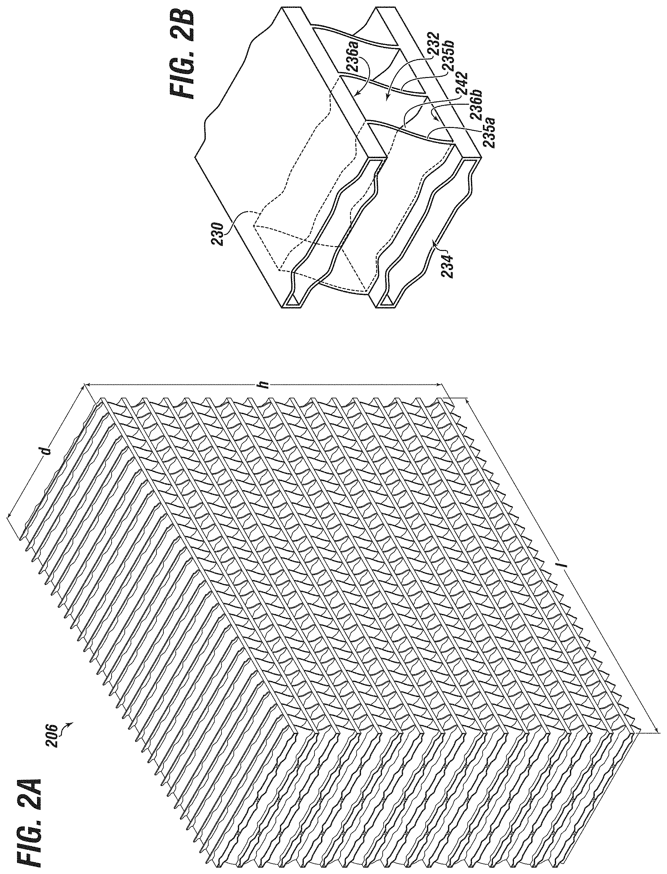
[0047] FIG. 2A shows an isometric view of a 3D printed radiator core according to embodiments of the disclosure;
[0048] FIG. 2B shows a zoom-in sectional view of a partial cell structure of the core of FIG. 2A according to embodiments of the disclosure;
[0049] FIG. 2C shows a sideview of a passageway of a single cell module of the core of FIG. 2A according to embodiments of the disclosure;
[0050] FIG. 2D shows a rotated side view of the passageway of FIG. 2C according to embodiments of the disclosure;
[0051] FIG. 2E shows, a side cross-sectional view of the passageway of FIG. 2D according to embodiments of the disclosure;
[0052] FIG. 2F shows, a side cross-sectional view of the passageway of FIG. 2D with fluid motion therethrough according to embodiments of the disclosure;
[0053] FIG. 2G shows a sideview of an adjacent passageway to the passageway of FIG. 2C according to embodiments of the disclosure; and
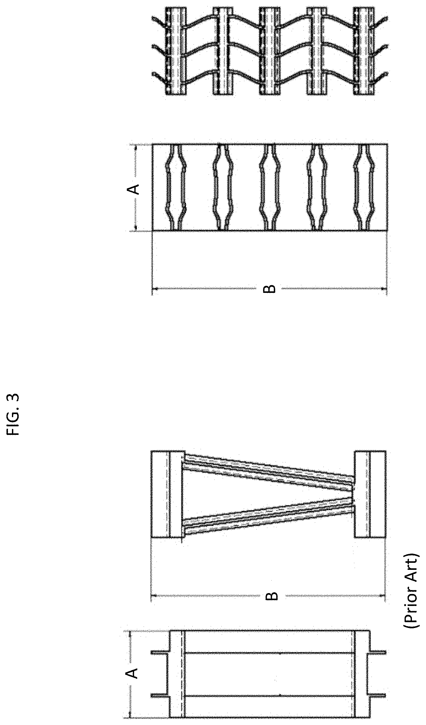
[0054] FIG. 3 shows a side view of a partial conventional cooler structure compared to a partial 3D printed cooler of the same size according to embodiments of the disclosure.
DETAILED DESCRIPTION
[0055] Herein disclosed are novel apparatuses, systems, and methods that pertain to an improved heat exchanger and aspects (including components) related thereto, details of which are described herein.
[0056] Embodiments of the present disclosure are described in detail with reference to the accompanying Figures. In the following discussion and in the claims, the terms "including" and "comprising" are used in an open-ended fashion, such as to mean, for example, "including, but not limited to . . . ". While the disclosure may be described with reference to relevant apparatuses, systems, and methods, it should be understood that the disclosure is not limited to the specific embodiments shown or described. Rather, one skilled in the art will appreciate that a variety of configurations may be implemented in accordance with embodiments herein.
[0057] Although not necessary, like elements in the various figures may be denoted by like reference numerals for consistency and ease of understanding. Numerous specific details are set forth in order to provide a more thorough understanding of the disclosure; however, it will be apparent to one of ordinary skill in the art that the embodiments disclosed herein may be practiced without these specific details. In other instances, well-known features have not been described in detail to avoid unnecessarily complicating the description. Directional terms, such as "above," "below," "upper," "lower," "front," "back," "right", "left", "down", etc., are used for convenience and to refer to general direction and/or orientation, and are only intended for illustrative purposes only, and not to limit the disclosure.
[0058] Connection(s), couplings, or other forms of contact between parts, components, and so forth may include conventional items, such as lubricant, additional sealing materials, such as a gasket between flanges, PTFE between threads, and the like. The make and manufacture of any particular component, subcomponent, etc., may be as would be apparent to one of skill in the art, such as molding, forming, press extrusion, machining, or additive manufacturing. Embodiments of the disclosure provide for one or more components to be new, used, and/or retrofitted to existing machines and systems.
[0059] Various equipment may be in fluid communication directly or indirectly with other equipment. Fluid communication may occur via one or more transfer lines and respective connectors, couplings, valving, and so forth. Fluid movers, such as pumps, may be utilized as would be apparent to one of skill in the art.
[0060] Numerical ranges in this disclosure may be approximate, and thus may include values outside of the range unless otherwise indicated. Numerical ranges include all values from and including the expressed lower and the upper values, in increments of smaller units. As an example, if a compositional, physical or other property, such as, for example, molecular weight, viscosity, melt index, etc., is from 100 to 1,000, it is intended that all individual values, such as 100, 101, 102, etc., and sub ranges, such as 100 to 144, 155 to 170, 197 to 200, etc., are expressly enumerated. It is intended that decimals or fractions thereof be included. For ranges containing values which are less than one or containing fractional numbers greater than one (e.g., 1.1, 1.5, etc.), smaller units may be considered to be 0.0001, 0.001, 0.01, 0.1, etc. as appropriate. These are only examples of what is specifically intended, and all possible combinations of numerical values between the lowest value and the highest value enumerated, are to be considered to be expressly stated in this disclosure.
[0061] Embodiments herein may be described at the macro level, especially from an ornamental or visual appearance. Thus, a dimension, such as length, may be described as having a certain numerical unit, albeit with or without attribution of a particular significant figure. One of skill in the art would appreciate that the dimension of "2 centimeters" may not be exactly 2 centimeters, and that at the micro-level may deviate. Similarly, reference to a "uniform" dimension, such as thickness, need not refer to completely, exactly uniform. Thus, a uniform or equal thickness of "1 millimeter" may have discernable variation at the micro-level within a certain tolerance (e.g., 0.001 millimeter) related to imprecision in measuring and fabrication.
Terms
[0062] The term "connected" as used herein may refer to a connection between a respective component (or subcomponent) and another component (or another subcomponent), which can be fixed, movable, direct, indirect, and analogous to engaged, coupled, disposed, etc., and can be by screw, nut/bolt, weld, and so forth. Any use of any form of the terms "connect", "engage", "couple", "attach", "mount", etc. or any other term describing an interaction between elements is not meant to limit the interaction to direct interaction between the elements and may also include indirect interaction between the elements described.
[0063] The term "fluid" as used herein may refer to a liquid, gas, slurry, multi-phase, etc. and is not limited to any particular type of fluid such as hydrocarbons.
[0064] The term "radiator" as used herein can refer to or interchangeable with the term `heat exchanger` or `heat exchanger panel`. The radiator can be a heat exchanger used to transfer thermal energy from one medium to another for the purpose of cooling and/or heating.
[0065] The term "cooler" as used herein can refer to a radiator made up of tubes or other structure surrounded by fins (or `core`) that can be configured to extract heat from a fluid moved through the cooler. The term can be interchangeable with `heat exchanger panel` or comparable. Heat can also be exchanged to another fluid, such as air.
[0066] The term "cooling circuit" as used herein can refer to a cooler and respective components.
[0067] The term "core" as used herein can refer to part of a cooler, and can include multiple layers of fins, fin elements, a lattice structure, or a plurality of interconnected cell modules.
[0068] The term "heat exchanger unit" as used herein can refer to a device or configuration that uses one or more coolers along with other components, such as a fan, mounts, tubing, frame, and so on. The heat exchanger unit can be independent and standalone or can be directly mounted to a heat generating device. The heat exchanger unit can be operable to pull (draw) ambient air in through the coolers in order to cool one or more service fluids. The heated air is moved or blown out as a waste exhaust stream. Or vice versa.
[0069] The term "heat generating device" (or sometimes `HGD`) as used herein can refer to an operable device, machine, etc. that emits or otherwise generates heat during its operation, such as an engine, motor, a genset, or a frac pump (including the pump and/or respective engine). The HGD can be for an industrial or a residential setting.
[0070] The term "genset" (or generator set) as used herein can refer to a `diesel generator` or the combination of a diesel engine (or comparable) and an electric generator. The genset can convert mechanical energy to electrical energy.
[0071] The term "utility fluid" as used herein can refer to a fluid used in connection with the operation of a heat generating device, such as a lubricant or water. The utility fluid can be for heating, cooling, lubricating, or other type of utility. `Utility fluid` can also be referred to and interchangeable with `service fluid` or comparable.
[0072] The term "mounted" as used herein can refer to a connection between a respective component (or subcomponent) and another component (or another subcomponent), which can be fixed, movable, direct, indirect, and analogous to engaged, coupled, disposed, etc., and can be by screw, nut/bolt, weld, and so forth.
[0073] Referring now to FIG. 1, an overview diagram of a 3D printing system in accordance with embodiments disclosed herein, is shown.
[0074] 3D printing (or additive manufacturing) system 100 may include a computer aided design (CAD) module 102 in operable communication with a 3D printing module 104. Operable communication may be via respective cabling, wireless, and so forth. Thus, a transceiver or the like may be used transmit data and instructions between the CAD module 102 and the 3D printing module 104. Alternatively, a wired or integrated setup may be used. Although not shown here, one of skill would appreciate system 100 may include various utility connections, such as power, cooling, ventilation, and so forth.
[0075] The CAD module 102 may be used for designing and generating a computer model of a part 106. Although not meant to be limited, embodiments herein provide for the part 106 to be a core (i.e., radiator core) for a heat exchanger. In this respect, the part 106 may have a repeatable cell structure of predetermined dimensioning, the size and repetitive nature being unachievable by regular CNC machining process and the like. The printed part 106 may be designed and sized for use as may be desired. For example, a radiator core may be designed and sized for fitting within a computer or mobile device. Alternatively, the radiator core may be designed and size for fitting in a heat exchanger unit for a frac skid (such as for a cooling a motor for a frac pump). The heat exchanger unit may be like that as provided for in the Applications, each incorporated herein in in its entirety for all purposes.
[0076] The CAD module 102 may include various subcomponents known to one of skill, such as computer 122 with a processor, a memory, a transceiver, a plurality of inputs and outputs, a display etc. The CAD module 102 may be integral with or separate from the 3D printing module 104.
[0077] The processor may be suitable (including respective computer instructions) for creating a computer model of the part 106 according to inputs and data received from a user. The processor may include a circuit board, memory, display, inputs, and/or other electronic components such as a transceiver or external connection for communicating with external computers and the like.
[0078] The processor may implement embodiments herein with one or more computer programs stored in or on computer-readable medium residing on or accessible by the processor. A computer program can be embodied in any suitable computer-readable medium for use by or in connection with an instruction execution system, apparatus, or device, such as a computer-based system, processor-containing system, or other system that can fetch the instructions from the instruction execution system, apparatus, or device, and execute the instructions, as would be known to one of skill.
[0079] The memory may be any computer-readable non-transitory medium that can store the program for use by or in connection with the instruction execution system, apparatus, or device. The computer-readable medium can be, for example, but not limited to, an electronic, magnetic, optical, electro-magnetic, infrared, or semi-conductor system, apparatus, or device. More specific, although not inclusive, examples of the computer-readable medium would include the following: an electrical connection having one or more wires, a portable computer diskette, a random access memory (RAM), a read-only memory (ROM), an erasable, programmable, read-only memory (EPROM or Flash memory), an optical fiber, and a portable compact disk read-only memory (CDROM).
[0080] The inputs may allow a user to design and modify a model of the part 106 and may comprise a keyboard 118, a mouse or touchpad 124, trackball, a touchscreen 116, buttons, dials, virtual inputs, and/or a virtual reality simulator. The inputs may also be used to control or instruct the 3D printing module 104. The computer 122 may be a desktop, laptop, or other suitable programmable device. The computer 122 may be configured with a synchronization unit 120 for interfacing with another computer or mobile device 114.
[0081] The printing module 104 may be any such module suitable to print the part 106. The module 104 may include a frame 108, a support surface 110, a material reserve, a feeder, a material applicator, a set of motors, a processor, and so forth. The 3D printing module 106 may include a powder coating system.
[0082] The frame 108 may provide the structure for the support surface 110, and other respective components. The frame 108 may include a base, horizontal member, vertical members, cross members, and mounting points for mounting the above components thereto. Alternatively, the frame 108 may be a walled housing or similar structure.
[0083] The support surface 110 may be configured to support the part 106 as it is being constructed and may be a stationary or movable flat tray or bed, a substrate, a mandrel, a wheel, scaffolding, or similar support. The support surface 110 may be integral with the 3D printing module 104 or may be removable and transferable with the part 106 as it is being constructed.
[0084] The material reserve may be suitable to hold 3D printing material, and may be in a known form such as a hopper, tank, cartridge, container, spool, or other similar material holder. The material reserve may be integral with the 3D printing module 104 or may be disposable and/or reusable.
[0085] Material suitable for embodiments herein may be for 3D printing techniques, such as Selective Laser Sintering (SLS), Direct Metal Laser Sintering (DMLS), Selective Laser Melting (SLM), and Fused Deposition Modeling (FDM). Thus, the part 106 may be made from metal or from other materials, such as plastics (including thermoplastics), composites, metal-infused plastics, or any other material suitable for 3D printing.
[0086] For example, the additive manufacturing material may be acrylonitrile butadiene styrene (ABS), Polyphenylene Sulphide (PPS), Polysulfone (PSU), Polytetrafluoroethylene (PTFE), Fluorinated Ethylene Propylene (FEP), Ethylene tetrafluoroethylene (ETFE), Polyetherimide (PEI), Polyethetersulfone (PES), PolyEtherEther-Ketone (PEEK), non-PEEK (including PAEK, PEK, PEKEEK, PEKK, and PFA), polyamidic (e.g., Polyamide 6--TA6'), Polycarbonate (PC), Poly(methyl methacrylate) (PMMA), straw-based plastic, or other similar material. The manufacturing material may originally be in pellet or powder form, filament or spooled form, or any other suitable form. A feeder may direct the additive manufacturing material to the applicator 112. The feeder may be in the form of a spool feeder, gravity feed, a pump, an auger, or any other suitable feeder.
[0087] Filler materials include additives such as milled carbon fiber, copper powder, copper fiber, and graphene. Such an additive may be used with a thermoplastic material to give the resultant 3D printed part better thermal conductivity properties.
[0088] In order to achieve beneficial weight reduction embodiments herein provide for new materials, including polymer-based composites, in manufacturing of heat exchanger components. In terms of cost and performance, these new materials are able to compete with metal-based materials such as aluminum and copper alloys. Specifically, these new and light-weight materials may be able to withstand the maximum fluid pressure requirements at operating temperatures as high as 250.degree. F. Also, these composites may be thermally conductive enough to preserve the thermal efficiency. In addition, the new materials may yet further be compatible with 3D printing technology.
[0089] Research has shown that the more metallic additive used with plastic, the better the thermal conductivity; however, glass transition temperature may be detrimentally affected. Comprehensive research was thus carried out to identify and test potential thermoplastics that may be used in developing the new composite materials. Glass transition temperature as an indicator of mechanical strength, water absorption, thermal conductivity, and printability constitute key criteria considered and tested. Results showed that only a few categories of thermoplastics are strong enough to operate at high temperatures while showing a good hydrolysis resistant. ABS, PEEK, and PPSU are example thermoplastics that successfully passed mechanical and hydrolysis tests. These three thermoplastics were also used in a 3D printer and the results were satisfactory. However, the thermal conductivity of these plastics was viewed as too low and therefore using them in heat exchange applications may result in significantly reduced the thermal efficiency.
[0090] Thus, metal additives or fillers were considered for addition to polymer-based composites in order to achieve higher thermal conductivities. Acrylonitrile Butadiene Styrene (ABS) was chosen as an example matrix for the new composite. Two different types of metallic additives, namely copper powder and chopped copper fiber were tested as a reinforcing phase. The size of the copper powder varied from about 10 micrometers to about 300 micrometers in average bulk diameter. The copper fiber had an average bulk diameter of about 20 micrometers to about 60 micrometers, with an average length that varied from about 50 micrometers to 400 micrometers. ABS was mixed alternatively with these additives in various ratios through a single screw extruder.
[0091] Extrusion occurred at a temperature range of 180.degree. C. to 210.degree. C., extruding a 3 mm filament suitable for use in 3D printer in accordance with embodiments herein. In addition to testing the thermal conductivity of the composite filaments, testing was also conducted to ensure that the mechanical strength and the integrity of the new composites remain in the acceptable range.
[0092] The results indicate that adding metallic additives, such as copper, improves the thermal conductivity of ABS. The change in thermal conductivity was found to be more significant in copper fiber infused filaments rather than copper powder infused filaments. Microstructural analysis shows that copper fibers may create many continuous paths through the matrix (percolation phenomenon) that may carry heat, whereas while copper powders may create discontinuous paths that do not have a significant impact on the capability of matrix to conduct heat.
[0093] Although adding copper additives improves the thermal conductivity of ABS, the glass transition temperature and therefore the mechanical strength of the composites drop as the amount of copper additives increases. Testing filaments with various ratios of copper fiber and ABS indicates that the maximum acceptable ratio is about 40% copper fiber. Infusing higher amounts of copper fiber may reduce the mechanical strength of the composites below the acceptable ranges of anticipated operating conditions. Embodiments herein provide for a base matrix material infused with a metallic additive, the resultant filament material having about 10% to about 50% by weight of the metallic additive.
[0094] A difficulty in the manufacturing of copper infused filaments was also addressed. Copper infused filaments that come out of the extruder may be too brittle to be directly fed into the 3D printer. These filaments may easily break under the pressure of the driving system in a 3D printer. It was discovered that this issue is mainly induced by nonuniform distribution of copper additives within the matrix as areas with higher densities of copper fiber are prone to cracking.
[0095] It was discovered that chopping the infused filament into pellets may be beneficial. That is, the copper infused filament may be chopped into pellets after a first extrusion. The copper infused pellets were then fed back into the extruder. The results indicated that subsequent, or multiple, extrusion(s) leads to more uniform distribution of the second phase in the filaments and therefore improves the flexibility of the copper infused filaments. About 1 to 4 rounds of extrusion may yield an optimum ductility.
[0096] Thus, embodiments herein provide for forming a first infused filament. Chopping or cutting the first infused filament into pellets. Extruding the first infused filament pellets, and repeating as may be desired, to form a 3D printing material for use in system 100.
[0097] In operation, the material applicator 112 may deposit a selected 3D printing material onto the support surface 110 (and/or on previously constructed layers of the part 106). The material applicator 112 may include a nozzle, guide, sprayer, or other similar component for channeling the additive manufacturing material and a laser, heater, or similar component for melting the additive manufacturing material and bonding (e.g., sintering) the additive manufacturing material onto a previously constructed layer. The material applicator 112 may be sized according to the size of the pellets, powder, or filament being deposited.
[0098] Motors may be used for positioning the material applicator 112 over the support surface 110, and thereby moving during the deposit application. Motors may be configured in such a manner whereby the material applicator 112 may be moved in a lateral "x" direction, a longitudinal "y" direction, and an altitudinal "z" direction. In aspects, motors may alternatively move the support surface 110 (and hence the part 106) while the material applicator 112 may be stationary.
[0099] One of skill would appreciate the 3D printing system 100 may be any type of additive manufacturing or "3D printing" system such as a sintering, laser melting, laser sintering, extruding, fusing, stereolithography, extrusion, light polymerizing, powder bed, wire additive, or laminated object manufacturing system. The 3D system 100 may also be a hybrid system that combines 3D printing with machining, molding, scaffolding, and/or other subtractive manufacturing or assembly techniques.
[0100] Referring now to FIGS. 2A, 2B, 2C, 2D, 2E, and 2F together, an isometric view of a 3D printed radiator core, and a zoom-in sectional view of a partial cell structure of the core of FIG. 2A, a sideview of a passageway of a single cell module of the core of FIG. 2A, a rotated side view of the passageway of FIG. 2C, a side cross-sectional view of the passageway of FIG. 2D, a cross-sectional view of the passageway of FIG. 2D with fluid motion therethrough, and a lateral cross-sectional view of an adjacent passageway, respectively, in accordance with embodiments disclosed herein, are shown.
[0101] Although 3D printing has been around for decades, related printing processes have not been of great consideration for industrialized heat exchange technology. FIG. 2A shows a radiator core 206 that may be 3D printed (such as via system 100), including with any material described herein. Although not limited to any particular overall shape, FIG. 2A illustrates the core 206 may be generally rectangular prism in nature. Thus, the core 206 may have a size (or volume) characterized by a length l, a height h, and a depth d. In a non-limiting example, length l may be in the range of about 70'' to about 90''; height h may be in the range of about 55'' to about 75''; depth d may be in the range of about 4'' to about 8''.
[0102] The core 206 may be 3D printed with varied structure. As shown, the core 206 may have a lattice structure with multiple, repeatable cell module structure(s) 230. Although a myriad of ways exist to characterize the structure of the core 206, one such manner is to refer to the cell structure 230. Much like an organic `cell`, the cell structure 230 may be contemplated as the basic structure and building block of the core 206. In this instance, the cell structure 230 may be referred to as the interaction or interface between adjacent, yet isolated fluid passageways 232, 234 (i.e., fluid within passageway 232 may be kept from being in fluid communication with fluid in passageway 234). In aspects, the first fluid passageway 232 may accommodate a gaseous fluid, such as air (or airflow), while the second fluid passageway 234 may accommodate a liquidious fluid, such as water or a water-based (aqueous) mixture.
[0103] The single cell module (or `module`) 230 may include the first fluid passageway 232 that may be defined by the arrangement of a first sidewall 235a, and a second sidewall 235b. The first sidewall 235a may be coupled (in this instance, indirectly) with the second sidewall 235b via a top deck 236a and a bottom deck 236b. The top deck 236a may correspond to a bottom of fluid passageway 234a. In a similar manner, the bottom deck 236b may correspond to a top of fluid passageway 234b. The outermost surfaces of the top and bottom decks 236 a, b through the passageway by be linear in lateral cross-section, whereas the outermost surfaces of the sidewalls 235 a, b may be curvilinear in lateral cross-section.
[0104] The first sidewall 235a and the second sidewall 235b may have a respective thickness T2. Although the thickness T2 of any particular sidewall (of core 206) may be equal or uniform at the visual level, there may be variation within a certain tolerance. Just the same, the thickness T2 need not be equal, and thus may indeed be varied. Thickness T2 may be in the range of about 0.1 mm to about 0.5 mm.
[0105] The top deck 236a and the bottom deck 236b may have a respective thickness T1. Although the thickness T1 of any particular top or bottom deck (of core 206) may be equal or uniform at the visual level, there may be variation within a certain tolerance. Just the same, the thickness T1 need not be equal, and thus indeed may be varied. Thickness T1 may be in the range of about 0.1 mm to about 0.5 mm.
[0106] Thickness T1 and/or T2 may have a direct impact on overall size of the core 206, as well as heat transfer characteristics. Too thin of material thickness may result in fragility or be non-printable; too thick of material may decrease heat transferability or increase costs.
[0107] The outermost surfaces of the top deck 236a and the bottom deck 236b may be separated by spacing of a height h1. The height between any two points may vary along a length of the passageway 232. Although the first sidewall 235a and the second sidewall 235b may have a relative height equal to that of the height h1, FIG. 2D illustrates a curvilinear nature of the each of the sidewalls 235 a, b whereby if the sidewalls were flattened (straightened out), the respective height would be larger than that of the height h1. FIG. 2D further illustrates midpoint reference 238 may divide a respective sidewall to the point that the reflection of an upper half need not mirror the lower half. On the other hand, were one of the sidewalls 235 a, b rotated 180.degree. around a pivot point P1, it may have the same appearance, and thus symmetry. Still, sidewalls of any cell module of the core 206 need not be curvilinear nor uniform, and may have variation in height.
[0108] The sidewalls 235 a, b may have a dual curvature characteristic represented by respective radius of curvatures r1, r2. In aspects, r1 may be equal to r2 within a given tolerance. The equal and opposite appearance of r1 and r2 provides a `wavy` or sinusoidal orientation of sidewalls 235 a, b. Although the sidewalls of any module of the core 206 may have varied shapes (in cross-section), including linear, the repetitive nature of a sinusoidal shape may provide desired synergy of improved pressure drop and improved heat transfer characteristics for fluid passages 232 of the core 206. The curvature of r1 and/or r2 may be in the range of about 2.degree..
[0109] In aspects, the curvilinear nature of the sidewalls 235 a, b may provide additional surface area for heat transfer for module 230, as compared to lesser surface area with linear sidewalls of a comparable height.
[0110] The sidewalls 235 a, b may be separated by a spacing length l1. Although it need not be, the lateral spacing between any given pair of lateral cross-sectional points between respective sidewalls may be equal. Thus, as shown here l1 may be equal to l1a. l1 may be in the range of about 1 mm to about 5 mm.
[0111] Either or both of the top deck 236a and the bottom deck 236b may have one or more ridge or fin-shape surfaces. In aspects, module 230 may have at least one ridge surface 242 associated therewith. Although not limited, passageway 232 may have between about 0 to about 6 ridges associated therewith. FIG. 2C illustrates a plurality of four ridges 242 with 242 a, b, c. In contrast to conventional radiator cores, 3D printed core (206) has the unique characteristic of having shared surface interaction between fluid passageways 232 and 234. That is, passageways for conventionally manufactured cores are not only fluidly isolated, but also structurally isolated, typically by the presence of one or more plates between adjacent passageways (i.e., fin layers).
[0112] FIGS. 2E-2F exemplify a given flow passage through a respective cell module may have one or more flow regimes. The cell module 230 may have a generally uniform flow regime, which may be achievable by having continuous, including linear, and/or planar horizontal/vertical, uniform surfaces. This type of flow regime may be desirous in certain applications, and may be characterized as having a low pressure drop. However, in other applications it may be desirous to have discontinuous surfaces.
[0113] It has been discovered that the parameters related to the geometry of the cell module 230 directly relates to thermal conductivity and pressure drop performance. One of skill in the art would greatly appreciate that modifying structure of the passageway 232 may have a significant impact on the heat transferability and/or pressure drop of the other passageway 234, and vice versa. This is particularly the case when the mediums are different, such as gaseous and liquidious.
[0114] Thus, in contrast to conventional cores, where fin isolation provides for independent fin design, with 3D printing, it is of significance that there is dependence between adjacent passageways 232, 234.
[0115] FIG. 2E illustrates a non-limiting example of various discontinuities on the top deck 236a and the bottom deck 236b that effect not only fluid flowing through passageway 232, but also adjacent passageways 234 a and b.
[0116] In this example, fluid may enter passageway 232 at position F1 (tantamount to an inlet of the cell module 230) with the least amount of resistance or obstruction (see height h1). The fluid may come from the inlet of the heat exchanger (such as from a tank) or from a preceding cell module. As the fluid moves with appreciable velocity to position F2, the fluid may eddy as a result of the narrowing space (see height h2) formed by an at least one ride portion 242. As shown in the Figures together, there may be an upper ridge portion 242b on the top deck 236a and a lower ridge portion 242a on the bottom deck 236b (see FIG. 2C). Narrowing at point F2 may be reduced spacing between at least one ridge and opposite deck surface. In aspects, narrowing at point F2 may be spacing between two respective ridges.
[0117] Accordingly a midpoint of a crest of one ridge (e.g., 242a) may be on the same vertical axis (e.g., an axis parallel to reference line 244) as a midpoint of a crest of another ridge (e.g., 242b). The distance between the underside of each ridge (e.g., h6) may be in a range of about 0.25 mm to about 3 mm.
[0118] Similarly, the top most point of a crest of one ridge (e.g., 242a) may additionally or alternatively be on the same horizontal axis (e.g., an axis parallel to reference line 238) as the top most point of another crest of another ridge (e.g., 242). A distance from top most midpoint to another top most midpoint on a horizontal may be in the range of about 0.5 mm to about 7 mm.
[0119] Eddies may desirably provide a suitable amount of instability and stirring within the flow regime of the cell module 230 whereby heat transfer is improved. However, eddies may undesirably attribute to increases in pressure drop. The ridge portion or structure of the cell module is not meant to be limited. The cell module 230 may have varied ridge portions on a respective top deck and/or bottom deck. Moreover, the ridge portion need not be uniform across the lateral length l1 of the passageway 232. Even furthermore, cell modules of an entire core may have varied ridge portions.
[0120] As shown here, ridges 242 with 242 a, b, c may be uniform and symmetrical, resulting in a mirrored appearance with respect to midline 250.
[0121] Although shown in cross-section with a form tantamount to a `wave` with a curved or curvilinear ridge with a crest/trough (see radii Ra, Rb, Rc), any ridge may be pyramidal, frustoconical, or other printable shape, or have associated linear surfaces. The presence of one or more ridges may provide narrowing between the top deck 236a and the bottom deck 236b. In embodiments, h2 may be less than h1.
[0122] As the fluid transitions from F2 to F3, the swirling effect of the eddies promotes better heat transfer from the decks 236 a, b to the fluid as it moves thereby. However, it may be useful to curtail the turbidity by trailing the crest back to flat, planar surfaces of the decks 236 a, b. The `calming` effect on the fluid at point F3 may be useful for curtailing pressure drop through the passageway 232. In embodiments, h3 may be about equal to h1. In other embodiments, h3 may be less than h1, but greater than h2.
[0123] The fluid may then transition from F3 to F4 in the presence of one or more ridges 242 a, b. As with ridges 242 and 242c, as the fluid moves with appreciable velocity to position F4, the fluid may eddy as a result of the narrowing space (see height h4) formed by an at least one ridge portion. As shown here, there may be another (a second, etc.) upper ridge portion 242b associated with the top deck 236a and another (second, third, etc.) lower ridge portion 242a associated with the bottom deck 236b.
[0124] A subsequent calming of the fluid may occur as the fluid transitions from F4 to F5, where again the top deck and the bottom deck 236 a, b become flat or planar. As shown, the decks 236 a, b at point F5 may be separated by clearance h1a. Although not meant to be limited, h1a may be about equal to h1. In aspects, one or both of h1 and h1a may be in the range of about 2 mm to about 4 mm. The fluid may then exit what is tantamount to an `outlet` of the cell module 230 and move to the next cell, or exit the core, and out of the heat exchanger.
[0125] The flow regimes within passageway 232 may be epitomized by surface geometry. One parameter of particular interest is the ratio of d1:d2. Distance or depth d1 may be the length between an entrance of the passageway 232 to ridge bisect or midpoint 244 (i.e., a reference line bisecting the approximate middle of ridge 242 and/or 242c). Distance or depth d2 may be the length between an entrance of the passageway 232 to passageway bisect or midpoint 250 (i.e., a reference line bisecting the approximate middle of passageway 232). In aspects, the ratio of d1:d2 nay be in the range of about 0.4 to about 0.6. In aspects, the ratio of d1:d2 nay be in the range of about 0.5. As result of symmetry, the ridges 242a and/or 242b may be contemplated in a similar manner from the opposite entrance (or exit, depending).
[0126] FIG. 2G is a look-through side view of passageway 234b. In aspects, passageways 232 and 234 may be similar, or even exact to each other. This may be the case when the fluids are comparable or identical, such as two airstreams. However, passageways 232 and 234 may also differ, which may be particularly useful when the fluids are of different mediums, namely, gaseous and liquidious. In embodiments, air may flow through passageway 232, while a liquid medium may flow through passageway 234.
[0127] The passageway 234b may be defined by side partitions 240 a, b and the top deck 236b and the bottom deck 236c (noting that the top deck 236b in this view is referenced as the bottom deck 236b for passageway 234 in FIG. 2D). The partitions and decks may be curvilinear in nature, including some partial linear and partial curvature. One of or both of decks 236 b, c may have at least one ridge 242. Although viewed here as a `wave` with a crest/trough-type structure, the at least one ridge 242 could have other shapes, such as pyramidal, frustoconical, etc.
[0128] The lateral distance d3 from an innermost surface of partition 240a to an opposite innermost surface of partition 240b may be in the range of about 5 mm to about 9 mm.
[0129] A crest 246 of the ridge 242 may have an amplitude 248 (with reference to topmost surface 249 of deck 236b of topmost surface of the crest 246) of about 0 mm (thus flat) to about 1.5 mm. In this sense, the passageway 234 may have varied space or clearance ranging from its narrowest height of h5 to its broadest or most open height of h6. h5 may be in the range of about 0.1 to about 1.5 mm. h6 may be in the range of about 0.25 mm to about 3 mm. In some embodiments, h5 may be equal to h6.
[0130] Embodiments herein provide for considerably smaller details to be printed in a more dense nature than traditional cooler manufacturing methods. Conventional manufacturing methods utilize a stamping process to produce fins of various geometric shapes and sizes. However typical stamping processes have limitations in the resultant sizes and shapes that can be achieved. For example, too thin of material will tear during the stamping process and complex shapes and patterns may not be possible to stamp and then remove from the die. Finally stamping has limitations on the fidelity of the feature detail that is possible to transfer from the die to the material plate being formed, very small and precise details may not transfer properly to the plate during the process.
[0131] Casting material is not practical due to the complex shape and need for cores and molds to form those shapes. Most casting processes use casting sand or some non-metallic foam as the mold or form. Keeping those patterns in the proper location during the pouring and solidification process for such small compact details is not possible. Machining evening using advanced CNC machines can only achieve certain level of detail due to limitations of cutter head size and axis of rotation of the cutting head during machining.
[0132] Embodiments herein provide for the capability to manufacture finer details in the fin geometry which can impact cooler performance. Because smaller parts can be printed with great fidelity, it is now possible to print these details into a far greater density than can be achieved via traditional stamping, casting or machining manufacturing processes. FIG. 3 shows a conventional stamped cooler design with two fluid passages one at the top and one at the bottom and a single cross fluid passage in between (labeled as `prior art`). By way of an example comparison, with in the same spacing (A and B), embodiments herein provide for five fluid passages with five cross fluid passages is now possible. The exact number of passages and spacing between them can vary based on design needs and fluids being transferred through the passages. More passageways, without detrimental pressure drop, is a radical change (and substantial improvement in heat transfer) over conventional coolers.
ADVANTAGES
[0133] Embodiments of the disclosure advantageously provide for an improved heat exchanger unit useable with a wide array of heat generating devices.
[0134] Advantages herein provide for a radiator core 3D printed out of a base material such as aluminum with a specific base metallurgical content. During manufacturing a tank may be welded to the cooler core forming a sealed pressure vessel for the fluid passage (such as water, glycol or oil) to flow through. During conventional core manufacturing the cooler core is made by brazing plates and fins together and then the tank is welded to the core. The welding process generates a heat which is higher than the melting point of the brazing material, thus causing what is referred to as braze leaching. This leaching can weaken or even fail the previously brazed joints of the core. With 3D printing the melting point of the core material is now the same as the tank material thus eliminating the potential for brazing failures at the weld seam.
[0135] 3D printing allows for higher fidelity details in the fin design which facilitates improved heat transfer between the two fluid mediums. By creating special features such as bumps, risers, curves, divots, windows and other features the fluid can be controlled to create turbulence, eddy currents and laminar flow at precise points along the fluid flow path thus facilitating increase thermal efficiency and heat transfer. Traditional manufacturing methods such as stamping simply do not allow for great enough fidelity to generate these details to the level that 3D printing can achieve.
[0136] 3D printing allows for the elimination of separation plates which contain the cladding or brazing material used in conventional cooler manufacturing. Using conventional manufacturing processes, a separation plate between the two fluid passageways is required to braze the fins from the two cross passages together. This plate is cladded with a brazing material that melts at a certain temperature thus brazing the fins and separator bars to together forming the passageways for the fluid mediums. 3D printing eliminates the need for this separation plate since the fins or top and bottom of one passage way, actually can form the floor or roof of the passageway that runs perpendicular to the other passageway. This eliminates weight, space and cost of the parts used to create these passages.
[0137] The process of alternative manufacturing for a cooler would eliminate the potential for operator mistakes during the manufacturing process of the cooler cores. Errors in stacking fins, bars and plates with one another would be eliminated. More importantly, the brazing process utilized today is not as scientific as one might believe and the process leads to inconsistency in the brazing results which effects cooler core durability and operational pressures. 3D printing of cooler cores would yield a greater consistency in material quality and molecular structure of the core thus improving durability.
[0138] While embodiments of the disclosure have been shown and described, modifications thereof can be made by one skilled in the art without departing from the spirit and teachings of the disclosure. The embodiments described herein are exemplary only, and are not intended to be limiting. Many variations and modifications of the disclosure presented herein are possible and are within the scope of the disclosure. Where numerical ranges or limitations are expressly stated, such express ranges or limitations should be understood to include iterative ranges or limitations of like magnitude falling within the expressly stated ranges or limitations. The use of the term "optionally" with respect to any element of a claim is intended to mean that the subject element is required, or alternatively, is not required. Both alternatives are intended to be within the scope of any claim. Use of broader terms such as comprises, includes, having, etc. should be understood to provide support for narrower terms such as consisting of, consisting essentially of, comprised substantially of, and the like.
[0139] Accordingly, the scope of protection is not limited by the description set out above but is only limited by the claims which follow, that scope including all equivalents of the subject matter of the claims. Each and every claim is incorporated into the specification as an embodiment of the present disclosure. Thus, the claims are a further description and are an addition to the preferred embodiments of the disclosure. The inclusion or discussion of a reference is not an admission that it is prior art to the present disclosure, especially any reference that may have a publication date after the priority date of this application. The disclosures of all patents, patent applications, and publications cited herein are hereby incorporated by reference, to the extent they provide background knowledge; or exemplary, procedural or other details supplementary to those set forth herein.
* * * * *
D00000
D00001
D00002
D00003
D00004
D00005
XML
uspto.report is an independent third-party trademark research tool that is not affiliated, endorsed, or sponsored by the United States Patent and Trademark Office (USPTO) or any other governmental organization. The information provided by uspto.report is based on publicly available data at the time of writing and is intended for informational purposes only.
While we strive to provide accurate and up-to-date information, we do not guarantee the accuracy, completeness, reliability, or suitability of the information displayed on this site. The use of this site is at your own risk. Any reliance you place on such information is therefore strictly at your own risk.
All official trademark data, including owner information, should be verified by visiting the official USPTO website at www.uspto.gov. This site is not intended to replace professional legal advice and should not be used as a substitute for consulting with a legal professional who is knowledgeable about trademark law.