Motor-operated Compressor
HER; Jongtae ; et al.
U.S. patent application number 16/519276 was filed with the patent office on 2020-01-30 for motor-operated compressor. This patent application is currently assigned to LG Electronics Inc.. The applicant listed for this patent is LG Electronics Inc.. Invention is credited to Soonyong CHOI, Jongtae HER, Kitae JANG, Jehoon KIM.
| Application Number | 20200032798 16/519276 |
| Document ID | / |
| Family ID | 67439011 |
| Filed Date | 2020-01-30 |


View All Diagrams
| United States Patent Application | 20200032798 |
| Kind Code | A1 |
| HER; Jongtae ; et al. | January 30, 2020 |
MOTOR-OPERATED COMPRESSOR
Abstract
A motor-operated compressor includes: a fixed scroll; an orbiting scroll engaged with the fixed scroll to perform an orbiting motion and forming a pair of compression chambers together with the fixed scroll during the orbiting motion; a frame provided opposite to the fixed scroll with the orbiting scroll interposed therebetween, and forming a back pressure chamber so as to axially support the orbiting scroll; and a rotation shaft coupled to the frame and the orbiting scroll in a penetrating manner. The rotation shaft is supported by the frame in a first axial direction and rotatably coupled to the fixed scroll, and an elastic member is disposed between the fixed scroll and the rotation shaft to support the rotation shaft in a second axial direction opposite to the first axial direction with respect to the first scroll.
| Inventors: | HER; Jongtae; (Seoul, KR) ; KIM; Jehoon; (Seoul, KR) ; JANG; Kitae; (Seoul, KR) ; CHOI; Soonyong; (Seoul, KR) | ||||||||||
| Applicant: |
|
||||||||||
|---|---|---|---|---|---|---|---|---|---|---|---|
| Assignee: | LG Electronics Inc. Seoul KR |
||||||||||
| Family ID: | 67439011 | ||||||||||
| Appl. No.: | 16/519276 | ||||||||||
| Filed: | July 23, 2019 |
| Current U.S. Class: | 1/1 |
| Current CPC Class: | F04C 2240/40 20130101; F04C 29/0021 20130101; F04C 27/005 20130101; F04C 2240/30 20130101; F04C 18/0269 20130101; F04C 18/0215 20130101 |
| International Class: | F04C 18/02 20060101 F04C018/02; F04C 27/00 20060101 F04C027/00 |
Foreign Application Data
| Date | Code | Application Number |
|---|---|---|
| Jul 26, 2018 | KR | 10-2018-0087383 |
Claims
1. A motor-operated compressor, comprising: a fixed scroll; an orbiting scroll engaged with the fixed scroll and configured to perform an orbiting motion relative to the fixed scroll, and the orbiting scroll and the fixed scroll forming a pair of compression chambers therebetween during the orbiting motion; a frame disposed opposite to the fixed scroll with the orbiting scroll interposed between the frame and the fixed scroll, a back pressure chamber being formed between the frame and the orbiting scroll, and the back pressure chamber being configured to axially support the orbiting scroll; a rotation shaft coupled to the frame and the orbiting scroll and penetrating through the frame and the orbiting scroll, and the rotation shaft being supported on the frame in a first axial direction and rotatably coupled to the fixed scroll; and an elastic member disposed between the fixed scroll and the rotation shaft, the elastic member being configured to support the rotation shaft in a second axial direction opposite to the first axial direction with respect to the fixed scroll.
2. The motor-operated compressor of claim 1, wherein: the fixed scroll includes a rotation shaft receiving portion configured to accommodate at least a part of the rotation shaft, and the elastic member is contained in the rotation shaft receiving portion.
3. The motor-operated compressor of claim 2, wherein: the rotation shaft receiving portion includes a support surface facing an end portion of the rotation shaft, and the elastic member is a coil spring having a first end supported by the end portion of the rotation shaft and a second end supported by the support surface.
4. The motor-operated compressor of claim 3, wherein the support surface includes a recessed guide groove configured to receive the second end of the elastic member.
5. The motor-operated compressor of claim 4, wherein: the end portion of the rotation shaft includes a protrusion portion extending in an axial direction from a center of the rotation shaft, and the elastic member is coupled to the protrusion portion.
6. The motor-operated compressor of claim 3, further comprising a bearing member disposed between the support surface and the elastic member.
7. The motor-operated compressor of claim 2, wherein: the rotation shaft receiving portion includes an inner circumferential surface corresponding to an outer circumferential surface of the rotation shaft, the inner circumferential surface includes a stepped mounting surface formed at a middle portion of the inner circumferential surface in an axial direction of the rotation shaft, and the elastic member is a leaf spring having opposite sides of the leaf spring supported by the end portion of the rotation shaft and the mounting surface.
8. The motor-operated compressor of claim 7, wherein the mounting surface is formed in a position facing the outer circumferential surface of the rotation shaft.
9. The motor-operated compressor of claim 1, wherein: the rotation shaft includes a thrust portion extending in a radial direction, the frame includes a frame shaft-receiving portion through which the rotation shaft passes, and the thrust portion is supported on the frame shaft-receiving portion in the first axial direction.
10. The motor-operated compressor of claim 9, wherein an annular sealing member is positioned between the thrust portion and the frame shaft-receiving portion.
11. The motor-operated compressor of claim 9, wherein facing surfaces of the thrust portion and the frame shaft-receiving portion are tilted relative to the axial direction of the rotation shaft.
12. The motor-operated compressor of claim 11, wherein an annular sealing member is interposed between the facing surfaces of the thrust portion and the frame shaft-receiving portion.
13. The motor-operated compressor of claim 11, wherein a thrust bearing is interposed between the facing surfaces of the thrust portion and the frame shaft-receiving portion.
14. A motor-operated compressor, comprising: a fixed scroll; an orbiting scroll engaged with the fixed scroll and configured to perform an orbiting motion relative to the fixed scroll, the orbiting scroll and the fixed scroll forming a pair of compression chambers therebetween during the orbiting motion; a frame disposed opposite to the fixed scroll with the orbiting scroll interposed between the frame and the fixed scroll, a back pressure chamber being formed between the frame and the orbiting scroll and configured to axially support the orbiting scroll, and the frame including a frame shaft-receiving portion; a rotation shaft coupled to the frame and the orbiting scroll and penetrating through the frame and the orbiting scroll, with the rotation shaft including a thrust portion supported on the frame shaft-receiving portion in a first axial direction, the rotation shaft being rotatably coupled to the fixed scroll; and a sealing member provided between the frame shaft-receiving portion of the frame and the thrust portion of the rotation shaft, the sealing member being configured to seal the back pressure chamber.
15. The motor operated compressor of claim 14, wherein: the thrust portion includes an inclined surface relative to an axial direction of the rotation shaft, and the frame shaft-receiving portion facing the inclined surface of the thrust portion includes a sealing surface formed along the inclined surface.
16. A motor-operated compressor, comprising: a fixed scroll; an orbiting scroll engaged with the fixed scroll and configured to perform an orbiting motion relative to the fixed scroll, and the orbiting scroll and the fixed scroll forming a pair of compression chambers therebetween during the orbiting motion; a frame disposed opposite to the fixed scroll with the orbiting scroll interposed between the frame and the fixed scroll, a back pressure chamber being formed between the frame and the orbiting scroll, and the back pressure chamber being configured to axially support the orbiting scroll; a rotation shaft coupled to the frame and the orbiting scroll and penetrating through the frame and the orbiting scroll, and the rotation shaft being supported on the frame in a first axial direction by a frame shaft-receiving portion of the frame and rotatably coupled to the fixed scroll, wherein the frame shaft-receiving portion mates with a thrust portion of the rotation shaft along facing surfaces of the frame shaft-receiving portion and the thrust portion of the rotation shaft that are inclined relative to a central axis of the rotation shaft; and an elastic member disposed between the fixed scroll and the rotation shaft, the elastic member being configured to support the rotation shaft in a second axial direction opposite to the first axial direction with respect to the fixed scroll.
17. The motor-operated compressor according to claim 16, wherein a thrust bearing member is disposed between at least a portion of the facing surfaces of the frame shaft-receiving portion and the thrust portion of the rotation shaft.
18. The motor-operated compressor according to claim 16, wherein a sealing member is disposed between at least a portion of the facing surfaces of the frame shaft-receiving portion and the thrust portion of the rotation shaft.
19. The motor-operated compressor according to claim 16, wherein: the fixed scroll includes a rotation shaft receiving portion configured to accommodate at least a part of the rotation shaft, and the elastic member is contained in the rotation shaft receiving portion.
20. The motor-operated compressor according to claim 19, wherein the elastic member is a spring.
Description
CROSS-REFERENCE TO RELATED APPLICATION
[0001] Pursuant to 35 U.S.C. .sctn. 119(a), this application claims the benefit of earlier filing date and right of priority to Korean Application No. 10-2018-0087383, filed on Jul. 26, 2018, the contents of which is incorporated by reference herein in its entirety.
BACKGROUND OF THE DISCLOSURE
1. Field of the Disclosure
[0002] The present disclosure relates to a motor-operated compressor.
2. Description of the Related Art
[0003] Generally, compressors for compressing a refrigerant in automotive air conditioning systems have been developed in various forms. Recently, motor-operated compressors driven by electric power using motors have been actively developed according to the tendency of electricization of electric parts of vehicles.
[0004] A motor-operated compressor mainly employs a scroll compression method suitable for a high compression ratio operation among various compression methods. In the scroll type motor-operated compressor, a motor unit configured as a rotary motor is provided in a hermetic casing, and a compression unit configured by a fixed scroll and an orbiting scroll is disposed at one side of the motor unit. The motor unit and the compression unit are connected to each other by a rotation shaft so that a rotational force of the motor unit is transferred to the compression unit. The rotational force transferred to the compression unit causes the orbiting scroll to perform an orbiting motion with respect to the fixed scroll, so as to form a pair of compression chambers each having a suction chamber, an intermediate pressure chamber, and a discharge chamber, so that a refrigerant is sucked into each of the compression chambers, compressed therein, and then simultaneously discharged.
[0005] As for the scroll compression method, a compressor having a shaft-through structure in which a rotation shaft passes through a compression unit has been disclosed. Specifically, a rotation shaft coupling portion coupled through a center of an orbiting scroll is formed, and an end portion of the rotation shaft, which is rotatably inserted into the rotation shaft coupling portion, is supported on a fixed scroll. With such a shaft-through structure, a compressive force and a repulsive force are applied to the same plane with respect to an orbiting scroll disk portion, and thus they are offset with each other, thereby preventing an orbiting scroll from being tilted caused by an action between the compression force and the repulsive force.
[0006] Here, a back pressure chamber is formed between the orbiting scroll and a frame. The back pressure chamber pressurizes the orbiting scroll to make close contact with the fixed scroll so as to maintain a sealed state of a compression chamber. Normally, the back pressure chamber is configured to communicate with an intermediate pressure chamber or a discharge pressure chamber. Accordingly, a refrigerant and oil having intermediate pressure or discharge pressure are introduced into the back pressure chamber so as to pressurize the orbiting scroll toward the fixed scroll.
[0007] However, in such a shaft-through scroll structure, the rotation shaft is not axially supported, thereby increasing axial vibrations of the rotation shaft. This causes a refrigerant and oil forming back pressure to leak to an outside of the back pressure chamber through a contact surface between the frame and the rotation shaft. Thus, stable back pressure is not generated in the back pressure chamber.
[0008] Particularly, when a specific level or amount of the back pressure is not generated at the beginning of operation of the compressor, behavior of the rotation shaft becomes unstable. Thus, pressure generation in the compression chamber is delayed.
SUMMARY OF THE DISCLOSURE
[0009] Therefore, one aspect of the present disclosure is to provide a motor-operated compressor capable of maintaining back pressure of a back pressure chamber.
[0010] Another aspect of the present disclosure is to provide a motor-operated compressor capable of maintaining a stable sealing state of a thrust surface for sealing a back pressure chamber by stabilizing axial movement or behavior of a rotation shaft.
[0011] Still another aspect of the present disclosure is to provide a motor-operated compressor capable of stabilizing axial movement or behavior of a rotation shaft by elastically supporting the rotation shaft in an axial direction.
[0012] Still another aspect of the present disclosure is to provide a motor-operated compressor capable of enhancing a sealing force of thrust surface by axially and radially supporting a rotation shaft.
[0013] In order to achieve the aspects of the present disclosure, there is provided a motor-operated compressor including an elastic member provided on one end of a rotation shaft to axially support the rotation shaft.
[0014] Here, an outer circumferential surface of the rotation shaft may be provided with a thrust portion extending in a radial direction, and the thrust portion may be supported on the frame shaft-receiving portion through which the rotation shaft passes in a direction opposite to the elastic member.
[0015] In addition, surfaces of the thrust portion and the shaft-receiving portion facing each other may be formed in an inclined manner.
[0016] Further, a sealing member may be fitted between the thrust portion and the shaft-receiving portion facing each other.
[0017] In order to achieve the aspects of the present disclosure, there is provided a motor-operated compressor including a fixed scroll, an orbiting scroll engaged with the fixed scroll to perform an orbiting motion and forming a pair of compression chambers together with the fixed scroll during the orbiting motion, a frame provided opposite to the fixed scroll with the orbiting scroll interposed therebetween in a radial direction, and forming a back pressure chamber so as to axially support the orbiting scroll, a rotation shaft coupled to the frame and the orbiting scroll in a penetrating manner and supported on the frame in a first axial direction so as to be rotatably coupled to the fixed scroll, and an elastic member disposed between the fixed scroll and the rotation shaft, so as to support the rotation shaft in a second axial direction opposite to the first axial direction with respect to the fixed scroll.
[0018] Here, the fixed scroll may be provided with a rotation shaft receiving portion that accommodates at least a part of the rotation shaft, and the elastic member may be provided in the rotation shaft receiving portion.
[0019] The rotation shaft receiving portion may include a support surface facing an end portion of the rotation shaft, and the elastic member may be implemented as a coil spring having both ends thereof supported by the end portion of the rotation shaft and the support surface.
[0020] The support surface may be provided with a guide groove recessed corresponding to the elastic member, and one end portion of the elastic member may be accommodated in the guide groove.
[0021] The end portion of the rotation shaft is provided with a protrusion portion extending to an axial direction from a center, and the elastic member may be inserted into and coupled to the protrusion portion.
[0022] The support surface and the elastic member may further include a bearing member disposed therebetween.
[0023] Here, the rotation shaft receiving portion may include an inner circumferential surface corresponding to an outer circumferential surface of the rotation shaft, the inner circumferential surface may be provided at a middle thereof with a mounting surface formed along an axial direction of the rotation shaft in a stepped manner, and the elastic member may be configured as a leaf spring having both sides thereof supported by the rotation shaft and the mounting surface.
[0024] The mounting surface may be formed in a position facing the outer circumferential surface of the rotation shaft.
[0025] Here, the rotation shaft may be provided with a thrust portion extending in a radial direction, and the frame may be provided with a frame shaft-receiving portion through which the rotation shaft passes. The thrust portion may be supported on the frame shaft-receiving portion in the first axial direction.
[0026] In addition, a sealing member with a ring shape may be fitted between the thrust portion and the frame bearing portion facing each other.
[0027] Surfaces of the thrust portion and the frame bearing portion facing each other may be formed to be tilted along the axial direction of the rotation shaft.
[0028] Also, a sealing member with a ring shape may be fitted between the thrust portion and the frame bearing portion facing each other.
[0029] Further, surfaces of the thrust portion and the frame shaft receiving portion facing each other are provided with a thrust bearing.
[0030] In order to achieve the aspects of the present disclosure, there is provided a motor-operated compressor including a fixed scroll, an orbiting scroll engaged with the fixed scroll to perform an orbiting motion and forming a pair of compression chambers together with the fixed scroll during the orbiting motion, a frame provided opposite to the fixed scroll with the orbiting scroll interposed therebetween in a radial direction, forming a back pressure chamber so as to axially support the orbiting scroll, and provided with a frame shaft-receiving portion, a rotation shaft coupled to the frame and the orbiting scroll in a penetrating manner and provided with a thrust surface to be supported on the frame shaft-receiving portion in a first axial direction so as to be rotatably coupled to the fixed scroll, and a sealing member provided between the frame shaft-receiving portion and the thrust portion of the rotation shaft so as to seal the back pressure chamber.
[0031] Here, the thrust portion may be provided with an inclined surface along an axial direction of the rotation shaft, and the frame shaft-receiving portion facing the inclined surface may be provided with a sealing surface formed in an inclined manner so as to correspond to the inclined surface.
EFFECTS OF THE DISCLOSURE
[0032] According to the present disclosure, one axial end of a rotation shaft is elastically supported to a frame. Thus, a sealing force between the rotation shaft and the frame can be enhanced. Accordingly, a back pressure chamber formed between an orbiting scroll and the frame is securely sealed so that back pressure of the back pressure chamber can be constantly maintained.
[0033] According to the present disclosure, as a rotation shaft is elastically supported by an elastic member in an axial direction, axial vibrations of the rotation shaft can be reduced. Accordingly, behavior of the rotational shaft is stabilized so that a sealing state of a back pressure chamber can be stably maintained.
[0034] Further, according to the present disclosure, a leakage in an axial direction of a compression chamber can be prevented by stabilizing behavior of a rotation shaft at the beginning of operation of the compressor, thereby increasing compressor efficiency.
[0035] Further, according to the present disclosure, an axial length of a rotation shaft receiving portion can be reduced by forming an elastic member provided on one end of the rotation shaft as a leaf spring, thereby contributing to a smaller compressor.
[0036] Further, according to the present disclosure, a thrust surface for supporting a rotation shaft is formed to be tilted, so that a frame can axially and radially support the rotation shaft. Thus, behavior of the rotation shaft can be more stable.
BRIEF DESCRIPTION OF THE DRAWINGS
[0037] FIG. 1 is a perspective view illustrating a compressor module and an inverter module separated from a motor-operated compressor according to one embodiment of the present disclosure.
[0038] FIG. 2 is a sectional view illustrating an inside of the motor-operated compressor according to FIG. 1.
[0039] FIG. 3 is a sectional view illustrating a main housing of the motor-operated compressor according to FIG. 2 when viewed from a side thereof.
[0040] FIG. 4 is a front view of the main housing of FIG. 3 when viewed from a rear side.
[0041] FIG. 5 is a sectional view of a rotation shaft and a bearing for supporting the rotation shaft according to the present disclosure.
[0042] FIG. 6 is a planar view illustrating an engagement relationship between an orbiting wrap and a fixed wrap having a non-involute shape in a motor-operated compressor according to one embodiment of the present disclosure.
[0043] FIG. 7 is a front view of a fixed scroll according to one embodiment of the present disclosure when viewed from a front side.
[0044] FIG. 8 is a sectional view of the fixed scroll of FIG. 7 when viewed from a side thereof.
[0045] FIG. 9 is a sectional view illustrating an engagement relationship between a rotation shaft, fixed and orbiting scrolls according to one embodiment of the present disclosure when viewed from a side thereof.
[0046] FIG. 10 is a sectional view illustrating an engagement relationship between a rotation shaft, fixed and orbiting scrolls in accordance with another embodiment of the present disclosure when viewed from a side thereof.
[0047] FIG. 11 is a sectional view of an inside of a motor-operated compressor according to another embodiment of the present disclosure.
[0048] FIG. 12 is a sectional view of a main housing in the motor-operated compressor according to FIG. 11.
[0049] FIG. 13 is a sectional view of a main housing according to a variation of the embodiment of FIG. 11.
DETAILED DESCRIPTION OF THE PREFERRED EMBODIMENTS
[0050] Description will now be given in detail of a motor-operated compressor according to exemplary embodiments disclosed herein, with reference to the accompanying drawings.
[0051] FIG. 1 is a perspective view illustrating a compressor module and an inverter module separated from a motor-operated compressor according to one embodiment of the present disclosure, and FIG. 2 is a sectional view illustrating an inside of the motor-operated compressor according to FIG. 1.
[0052] As illustrated, a scroll type motor-operated compressor (hereinafter, abbreviated as a "motor-operated compressor") according to the present disclosure may include a compressor module 101 for compressing a refrigerant, and an inverter module 201 coupled to a front side of the compressor module 101 for controlling operation of the compressor module 101. The compressor module 101 and the inverter module 201 may be assembled successively, or independently manufactured and assembled. This embodiment illustrates the latter as a representative example, but the former and the latter may alternatively be combined such that the compressor module and the inverter module are independently manufactured but successively assembled.
[0053] The compressor module 101 includes a main housing 110 having an inner space forming a motor chamber S1 and provided with an inlet port 111 formed thereat to communicate with the motor chamber S1, a driving motor 120 as a motor part fixed to the motor chamber S1 of the main housing 110, a compression unit 105 provided at one side of the driving motor 120 outside the main housing 110 to compress a refrigerant using a rotational force of the driving motor 120, and a rear housing 160 coupled to another side of the compression unit 105 to form an oil separation chamber S2.
[0054] As the main housing 110 is arranged in a horizontal direction with respect to the ground, the driving motor 120 and the compression unit 105 are also arranged in the horizontal direction. For the sake of explanation, a left side of FIG. 2 is designated as a front side and a right side as a rear side.
[0055] The main housing 110 is formed in a cross-sectional cup shape having an open front end and a partially closed rear end. The open front end of the main housing 110 is sealed by being coupled to an inverter housing 210 to be described later, and the partially closed rear end of the main housing 110 is integrally formed with the frame 112 supporting the compression unit 105. The frame 112 of the main housing 110 is provided with a frame shaft-receiving portion 113 formed in a cylindrical shape. A main bearing portion 132 of the rotation shaft 130 to be described later passes through the frame shaft-receiving portion to be rotatably supported.
[0056] A frame bearing 171 implemented as a bush bearing is inserted into and coupled to the frame shaft-receiving portion 113, and an inner circumferential surface of the frame shaft-receiving portion 113 is disposed apart from the main bearing portion 132 of the rotation shaft 130, so that a back pressure chamber S3, which will be described later, communicates with the motor chamber S1. The inlet port 111 connected to a suction pipe (not shown) is formed adjacent to the front end of the main housing 110, so that the motor chamber S1 of this embodiment forms a kind of suction space. Accordingly, in the motor-operated compressor according to this embodiment, a refrigerant is sucked into the compression unit through an internal space of the main housing constituting the motor chamber, thereby forming a low-pressure compressor.
[0057] In the main housing according to this embodiment, the frame is integrally formed, as described above. Accordingly, an additional process of assembling the frame to the main housing is not needed. Thus, a man-hour for assembly can be reduced and assemblability of a driving motor can be enhanced by eliminating the additional frame assembly process.
[0058] FIG. 3 is a sectional view illustrating a main housing of the motor-operated compressor according to FIG. 2 when viewed from a side thereof, and FIG. 4 is a front view illustrating the main housing of FIG. 3 when viewed from a rear side.
[0059] As illustrated, an axial center Ob1 of the frame shaft-receiving portion 113 is formed to coincide with an axial center Om of the driving motor 120. To this end, a center of an outer diameter and a center of an inner diameter of the frame 112 (i.e., a center of the frame-shaft receiving portion 113) may be formed to coincide with each other.
[0060] However, the axial center Ob1 of the frame shaft-receiving portion 113 may coincide with the axial center Om of the driving motor 120, but the center of the outer diameter Oo and the center of the inner diameter Oi of the frame 112 may not coincide with each other. For example, as illustrated in FIGS. 3 and 4, a first protrusion portion 114 is formed on one side in a radial direction of the frame 112, and a first passage 114a may be formed through the first protrusion portion 114 so as to communicate with an inside of the motor chamber S1. The first passage 114a may be provided with a suction passage Fg for communicating a compression chamber V with the motor chamber S1 together with a second passage 154a of a fixed scroll 150 to be described later.
[0061] A front side, which is the frame shaft-receiving portion 113, of the frame 112 extends to a central part, that is, a direction toward the driving motor 120, and a rear side of the frame 112 is formed to be recessed in a direction toward the driving motor 120 in a manner of having at least two steps. Accordingly, the frame 112 is provided at its rear side with a scroll receiving groove 112a in which an orbiting disk (or orbiting end plate) portion of an orbiting scroll to be explained later is inserted so as to be supported in an axial direction, an Oldham ring accommodating groove 112b for accommodating an Oldham ring 180, which is a rotation-preventing mechanism therein, and a balance weight accommodating groove 112c for rotatably accommodating a balance weight 138 therein. The scroll receiving groove 112a, the Oldham ring accommodating groove 112b, and the balance weight accommodating groove 112c are consecutively formed in a stepped manner so as to form a kind of back pressure chamber S3.
[0062] The rear end of the frame shaft-receiving portion 113 extends in a direction toward the orbiting scroll 140 and is formed in a cylindrical shape. The frame bearing 171 configured as a bush bearing is inserted into and coupled to the frame shaft-receiving portion 113. Accordingly, an outer circumferential surface of the rear end of the frame-shaft receiving portion 113 forms the balance weight accommodating groove 112c to create the back pressure chamber S3.
[0063] An axial bearing surface 113a, which forms a thrust surface together with a thrust portion 135 of the rotation shaft 130 to be described later, is provided at the rear end of the frame shaft-receiving portion 113.
[0064] Here, the axial bearing surface 113a of the frame shaft-receiving portion 113 and an axial bearing surface 135a of the thrust portion 135 provided on the rotation shaft 130 are in close contact with each other with the frame bearing 171 interposed therebetween, so as to seal the back pressure chamber S3. This prevents a refrigerant and oil forming back pressure of the back pressure chamber S3 from leaking through the thrust surface, thereby forming stable back pressure in the back pressure chamber S3. In this case, however, the refrigerant and oil accumulated in the back pressure chamber S3 may be introduced into the compression chamber again through a back pressure hole (not shown) formed in the fixed scroll 150.
[0065] The driving motor 120 includes a stator 121 inserted into and fixed to an inner circumferential surface of the main housing 110, and a rotor 122 positioned inside the stator 121 and rotated by interaction with the stator 121. The rotor 122 is coupled with a rotation shaft 130 that transfers a rotational force of the driving motor 120 to the compression unit 105 while rotating together with the rotor 122.
[0066] The stator 121 is fixed to the main housing 110 by shrink-fitting (or hot press fitting). Accordingly, a shorter length (or depth) for inserting the stator 121 into the main housing 110 may be more suitable for the assembly, and may also be suitable for maintaining concentricity of the stator 121 during the stator 121 shrink-fitting process.
[0067] To this end, as illustrated in FIG. 3, when the main housing 110 has a first end 110a, which is an open end, and a second end 110b at which the frame 112 is formed, a length L1 from an axial center CL of the stator 121 to the first end 110a may be formed to be shorter than a length L2 from the axial center CL of the stator 121 to the second end 110b. Accordingly, as described above, an insertion length L3 for inserting the stator 121 into the motor chamber S1 of the main housing 110 can be shortened.
[0068] On the other hand, the rotation shaft 130 is coupled to the center of the rotor 122 by shrink-fitting (or hot press fitting). Opposite ends of the rotation shaft 130 may be radially supported with the driving motor 120 interposed therebetween. However, as described in this embodiment, one end portion of the rotation shaft 130 may be one side of the driving motor 120, that is a fixed end radially supported at two points of the frame 112 and the fixed scroll 150, and another end portion of the rotation shaft 130 coupled to the rotor 122 of the driving motor 120 may be a free end in a radial direction.
[0069] FIG. 5 is a sectional view of a rotation shaft and a bearing for supporting the rotation shaft according to the present disclosure.
[0070] As illustrated, the rotation shaft 130 is provided with a shaft portion 131 coupled to the rotor 122, the main bearing portion 132 radially supported on the frame shaft-receiving portion 113 in a rotatable manner, an eccentric portion 133 eccentrically coupled to the orbiting scroll 140, and a sub bearing portion 134 radially supported on a scroll shaft-receiving portion 156 of the fixed scroll 150. The main bearing portion 132 and the sub bearing portion 134 radially support the rotation shaft 130, respectively, as described above. The eccentric portion 133 transfers a rotation force of the driving motor 120 to the orbiting scroll 140, so that the orbiting scroll 140 performs an orbiting motion by the Oldham ring 180.
[0071] An oil supply passage 136 is provided in the rotation shaft 130 by a predetermined depth in a direction toward the front end from the rear end. Oil supply holes 137a, 137b, and 137c are formed in a middle part of the oil supply passage 136 toward an outer circumferential surfaces of the main bearing portion 132, the eccentric portion 133, and the sub bearing portion 134, respectively. This will be described later again together with an oil supply structure.
[0072] Referring back to FIG. 2, as described above, the compression unit 105 includes the orbiting scroll 140 axially supported on the frame 112 of the main housing 110 to perform an orbiting motion, and the fixed scroll (or non-orbiting scroll) 150 coupled with the orbiting scroll 140 in an engaging manner and fixedly coupled to the second end 110b forming a closed end portion of the main housing 110. A pair of compression chambers V is formed between the orbiting scroll 140 and the fixed scroll 150 during the orbiting motion of the orbiting scroll 140. The compression chamber will be described later together with an orbiting wrap and a fixed wrap.
[0073] The orbiting scroll 140 is axially supported on the frame 112, and the Oldham ring 180 which is a rotation-preventing mechanism for preventing rotation of the orbiting scroll 140 is provided between the frame 112 and the orbiting scroll 140. A pin-and-ring type may also be used for the rotation-preventing mechanism.
[0074] In addition, the orbiting scroll 140 is provided with an orbiting scroll disk portion (hereinafter, referred to as "orbiting disk portion") 141 in a substantially disk shape. An orbiting wrap 142 is formed on a rear surface of the orbiting disk portion 141. The orbiting wrap 142 is engaged with a fixed wrap 153 to be explained later so as to form compression chambers at an inner surface and an outer surface with respect to the fixed wrap 153. The orbiting wrap will be explained later with the fixed wrap.
[0075] The orbiting disk portion 141 is provided with a back pressure hole 141a for communicating the back pressure chamber S3 and an intermediate compression chamber V with each other. Accordingly, oil or a refrigerant can flow between the back pressure chamber S3 and the intermediate compression chamber V according to a difference between pressure in the back pressure chamber S3 and pressure in the intermediate compression chamber V.
[0076] In addition, a rotation shaft coupling portion 143 to which the eccentric portion 133 of the rotation shaft 130 is rotatably coupled is formed through a central part of the orbiting disk portion 141. The rotation shaft coupling portion 143 is formed in a cylindrical shape, and a third bearing 173 forming a bearing surface together with the eccentric portion 133 of the rotation shaft 130 is inserted into the rotation shaft coupling portion 143. Accordingly, the rotation shaft coupling portion 143 (or third bearing) is formed so as to overlap the orbiting wrap 142 in a radial direction. The rotation shaft coupling portion 143 becomes a part of the orbiting wrap 142 which is located at the innermost position.
[0077] The fixed scroll 150, as aforementioned, may be coupled to the second end of main housing 110 from the outside of the main housing 110. In this case, a sealing member such as a gasket may be provided between the main housing 110 and the fixed scroll 150.
[0078] Referring back to FIG. 5, the rotation shaft 130 may be provided with one oil supply passage 136 and a plurality of oil supply holes 137a, 137b, and 137c. As described above, the oil supply passage 136 may be formed in the one end portion of the rotation shaft 130, that is, a direction to the front end of the rotation shaft 130 from the rear end of it accommodated in an oil guide space by a predetermined depth in an axial direction. The plurality of holes 137a, 137b, and 137c may be provided in the middle of the oil supply passage 136 in the axial direction at predetermined intervals therebetween.
[0079] The plurality of oil supply holes 137a, 137b and 137c may consist of a second oil supply hole 137b passing through an outer circumferential surface of the sub bearing portion 134, a third oil supply hole 137c passing through an outer circumferential surface of the eccentric portion 133, and a first oil supply hole 137a passing through an outer circumferential surface of the main bearing portion 132.
[0080] Accordingly, oil flowing into the oil supply passage 136 from the oil guide space passes through the second oil supply hole 137b, the third oil supply hole 137c, and the first oil supply hole 137a in order, and is then supplied to each respective bearing surface.
[0081] On the other hand, each of the orbiting wrap and the fixed wrap may be formed in an involute shape. However, as shown in this embodiment, when the rotation shaft is coupled through the center of the orbiting scroll, the final compression chamber may be formed in an eccentric position, and thus a great pressure difference may be generated between the compression chambers. This is because, in case of a shaft-through scroll compressor, pressure of one compression chamber becomes much lower than pressure of another compression chamber as the final compression chamber is formed eccentrically from a center of a scroll. Therefore, in the shaft-through scroll compressor, it is advantageous to form the orbiting wrap and the fixed wrap in a non-involute shape as shown in this embodiment.
[0082] FIG. 6 is a planar view illustrating an engagement relationship between an orbiting wrap and a fixed wrap in a non-involute shape in a motor-operated compressor according to one embodiment of the present disclosure.
[0083] As illustrated, an orbiting wrap 142 according the embodiment of the present disclosure may have a shape in which a plurality of arcs having different diameters and origins are connected, and the outermost curve may be formed in a substantially elliptical shape having a major axis and a minor axis. A fixed wrap 153 may be formed in a similar manner.
[0084] A rotation shaft coupling portion 143 which forms an inner end portion of the orbiting wrap 142 and to which an eccentric portion 133 of a rotation shaft 130 is rotatably inserted may be formed through a central portion of an orbiting disk portion 141 in an axial direction. A third bearing 173 implemented as a bush bearing may be fixedly inserted into an inner circumferential surface of the rotation shaft coupling portion 143. An outer circumferential part of the rotation shaft coupling portion 143 is connected to the orbiting wrap 142 to form the compression chamber V together with the fixed wrap 153 during a compression process.
[0085] Furthermore, the rotation shaft coupling portion 143 may be formed at a height overlapping with the orbiting wrap 142 on the same plane, and thus the eccentric portion 133 of the rotation shaft 130 may be disposed at a height overlapping with the orbiting wrap 142 on the same plane. Accordingly, a repulsive force and a compressive force of a refrigerant can be attenuated by each other while being applied to the same plane based on an orbiting disk portion, thereby preventing an inclination of an orbiting scroll 140 caused by an action of the compressive force and repulsive force.
[0086] The rotation shaft coupling portion 143 is provided with a concave portion 143a formed on an outer circumferential part thereof, which faces an inner end portion of the fixed wrap 153, and engaged with a protrusion portion 153a of the fixed wrap 153 to be explained later. An increasing portion 143b which increases in thickness from an inner circumferential part to the outer circumferential part of the rotation shaft coupling portion 143 is formed at an upstream side along a direction that a compression chamber V is formed. This may extend a compression path of the first compression chamber V1 immediately before discharge, and consequently a compression ratio of the first compression chamber V1 can be increased close to a compression ratio of the second compression chamber V2.
[0087] An arcuate compression surface 143c having an arcuate shape is formed at another side of the concave portion 143a. A diameter of the arcuate compression surface 143c is determined by a thickness of the inner end portion of the fixed wrap 153 (i.e., a thickness of a discharge end) and an orbiting radius of the orbiting wrap 142. When the thickness of the inner end portion of the fixed wrap 153 increases, a diameter of the arcuate compression surface 143c increases. As a result, a thickness of the orbiting wrap around the arcuate compression surface 143c may increase to ensure durability, and the compression path may extend to increase the compression ratio of the second compression chamber V2 to that extent.
[0088] In addition, a protrusion portion 153a is formed near the inner end portion (a suction end or a start end) of the fixed wrap 153 corresponding to the rotation shaft coupling portion 143 in a manner of protruding toward the outer circumferential part of the rotation shaft coupling portion 143. The protrusion portion 153a may be provided with a contact portion 153b protruding therefrom to be engaged with the concave portion 143a. In other words, the inner end portion of the fixed wrap 153 may be formed to have a larger thickness than other portions. As a result, wrap strength at the inner end portion of the fixed wrap 153, which is subjected to the highest compressive force on the fixed wrap 153, may increase so as to enhance durability.
[0089] On the other hand, the compression chamber V may be formed between the fixed end portion 151 and the fixed wrap 153, and between the orbiting wrap 142 and the orbiting end portion 141, respectively, and a suction chamber, an intermediate pressure chamber, and an oil separation chamber may be formed consecutively along a proceeding direction of the wraps.
[0090] The compression chamber V may include a first compression chamber V1 formed between an outer surface of the orbiting wrap 142 and an inner surface of the fixed wrap 153, and a second compression chamber V2 formed between an inner surface of the orbiting wrap 142 and an outer surface of the fixed wrap 153. In other words, the first compression chamber V1 includes a compression chamber formed between two contact points P11 and P12 generated in response to the inner surface of the fixed wrap 153 being brought into contact with the outer surface of the orbiting wrap 142, and the second compression chamber V2 includes a compression chamber formed between two contact points P21 and P22 generated in response to the outer surface of the fixed wrap 153 being brought into contact with the inner surface of the orbiting wrap 142.
[0091] Here, when a larger angle of angles formed between two lines, which connect a center of the eccentric portion, namely, a center O of the rotation shaft coupling portion to the two contact points P11 and P12, respectively, is defined as .alpha. within the first compression chamber V1 just before discharge, the angle .alpha. at least just before the discharge is larger than 360.degree. (i.e., .alpha.<360.degree.), and a distance lbetween normal vectors at the two contact points P11 and P12 also has a value greater than zero.
[0092] As a result, the first compression chamber immediately before the discharge, which is formed by the fixed wrap and the orbiting wrap according to the embodiment of the present disclosure, may have a smaller volume than that formed by a fixed wrap and an orbiting wrap having an involute shape. Therefore, the compression ratios of the first and second compression chambers V1 and V2 can all be improved even without increasing the size of the first wrap 142 and the second wrap 153.
[0093] A rear housing 160 is coupled to a second surface 150b of the fixed scroll 150. As the rear housing 160 is coupled to the second surface 150b of the fixed scroll 150, an oil separation chamber S2 may be formed such that a refrigerant discharged from the compression chamber V is accommodated therein.
[0094] Here, a separate protrusion portion (not shown) similar to a main-side fixing protrusion portion 115 and an inverter-side fixing protrusion portion 211, which will be described later, may be formed on outer circumferential surfaces of the rear housing 160 and the fixed scroll 150, respectively, to be fixed through a bolt, or a fixing bolt passing through an edge (rim) surface of the rear housing 160 may be fastened so as to be coupled to an edge surface of the fixed scroll 150. A sealing member such as a gasket may be provided between the rear housing 160 and the fixed scroll 150.
[0095] An inverter housing 210 may be coupled in a covering manner to one of both ends of the main housing 110, which is opposite to the rear housing 160, namely, coupled to the open front end of the main housing 110.
[0096] FIG. 7 is a planar view of a fixed scroll according to one embodiment of the present disclosure when viewed from a front side, and FIG. 8 is a sectional view of the fixed scroll according to FIG. 7.
[0097] As illustrated, the fixed scroll 150 includes a fixed scroll disk portion (hereinafter, referred to as "fixed disk portion") 151 formed in a substantially disk shape, and a side wall portion 152 formed at an edge of the fixed disk portion 151 to be coupled to a frame-side end of the main housing 110. A fixed wrap 153 which is engaged with the orbiting wrap 142 to form compression chambers is formed on a front surface of the fixed disk portion 151. As aforementioned, the fixed wrap 153 may be formed in an involute shape together with the orbiting wrap 142, but may also be formed in various other shapes.
[0098] A second protrusion portion 154 radially extends from an outer circumferential surface of the side wall portion 152 so as to correspond to the first protrusion portion 114. The second protrusion portion 154 may be provided therein with the second passage 154a constituting the suction passage Fg together with the first passage 114a. Accordingly, a center of an outer diameter Oso of the fixed scroll 150 may be different from a center Ob2 of the frame shaft-receiving portion 113.
[0099] The second passage 154a constituting the suction passage Fg may be formed in an axial direction, or may be formed to be inclined as shown in FIG. 8. When the second passage 154a is formed in the axial direction, an outer diameter of the fixed disk portion 151 may be enlarged to increase a winding length of the fixed wrap 153, compared to the same outer diameter of the main housing 110. On the other hand, when the second passage 154a is formed to be inclined, the winding length of the fixed wrap 153 compared with the same capacity of the compression chamber may be reduced so as to downsize the compressor.
[0100] As the first passage 114a and the second passage 154a constituting the suction passage Fg are formed in the first protrusion portion 114, and the second protrusion portion 135, receptively. Thus, the suction passage Fg may be formed close to an outer circumferential surface of the compressor. Accordingly, a refrigerant sucked into the compression chamber V through the 5 suction passage Fg from the motor chamber S1 can quickly exchange heat with external air of the compressor, which may lower a specific volume of the refrigerant sucked into the compression chamber V, thereby reducing a suction loss. Particularly, in the case of the second passage 154a, since the fixed scroll 150 is provided outside the main housing 110, the fixed scroll 150 is positioned closer to the outside than when the fixed scroll 150 is inserted into the main housing 110. Thus, a heat dissipation effect of a refrigerant slightly heated while passing through the motor chamber may be further increased.
[0101] Further, a dimple groove 152a may be formed on the outer circumferential surface of the side wall portion 152 to reduce a weight of the fixed scroll 150 and simultaneously prevent deformation of the fixed scroll 150. The dimple groove 152a may be provided in plurality arranged along a circumferential direction with predetermined intervals, or one dimple groove 152a may be formed long in the circumferential direction.
[0102] Since the outer circumferential surface of the side wall portion 152 of the fixed scroll 150 is located outside the main housing 110, an outer diameter of the fixed scroll 150 may be greater than or equal to an inner diameter of the main housing 110. Therefore, the outer diameter of the fixed scroll 150 can increase on the basis of the same outer diameter of the compressor, which may result in extending the winding lengths of the fixed wrap 153 and the orbiting wrap 142, thereby increasing a suction volume of the compression chamber V.
[0103] An outlet port 155 which communicates a final compression chamber V with an oil separation chamber S2 to be explained later so as to guide a discharge of a refrigerant is formed at a central part of the fixed disk portion 151. The outlet port 155 may be formed in a penetrating manner from the compression chamber V to the oil separation chamber S2 in an axial direction or inclined direction of the fixed disk portion 151. Only one outlet port 155 may be formed to communicate a first compression chamber V1 and a second compression chamber V2, or a first outlet port 155a and a second outlet port 155b may be formed to communicate with the first compression chamber V1 and the second compression chamber V2, respectively.
[0104] FIG. 9 is a sectional view illustrating an engagement relationship between a rotation shaft, first and second scrolls, in accordance with one embodiment of the present disclosure.
[0105] Referring to FIG. 9 together with FIG. 8, the rotation shaft 130 is formed to pass through the orbiting scroll 140 and the frame 112 of the main housing 110. In this case, the one end portion of the rotation shaft 130 is disposed to face the fixed scroll 150. As aforementioned, the scroll shaft-receiving portion 156 that radially supports the rotation shaft 130 is formed at a center of the fixed disk portion 151 of the fixed scroll 150. The scroll shaft-receiving portion 156 is provided with a rotation shaft receiving portion 156c formed therein to accommodate the one end portion of the rotation shaft 130.
[0106] The scroll shaft-receiving portion 156 may be formed by increasing a thickness of the fixed disk portion 151. In this case, however, not only a weight of the fixed scroll 150 is increased but also an unnecessary portion is thickly formed. As a result, a length of the outlet port 155 may become long, thereby increasing a dead volume. Therefore, as illustrated, a part of the fixed disk portion 151 may be formed to protrude. That is, it may be formed to radially extend from the fixed disk portion 151 to the rear housing 160.
[0107] A second bearing 172 may be inserted into the scroll shaft-receiving portion 156 to radially support the rotation shaft 130. The scroll shaft-receiving portion 156 is formed in a cylindrical shape having a closed rear surface, so that the second bearing 172, which forms a bearing surface together with the sub bearing portion 134 of the rotation shaft 130, is inserted into and coupled to an inner circumferential surface 156b of the second shaft receiving portion 156. The second bearing 172 may be implemented as a bush bearing or a needle bearing.
[0108] Here, the scroll shaft-receiving portion 156 may be formed to be longer in an axial direction than an accommodated length of the rotation shaft 130. In other words, the rotation shaft receiving portion 156c may extend toward the rear housing. In this case, as illustrated, an extra space not occupied by the rotation shaft 130 is created in the rotation shaft receiving portion 156c. The extra space of the rotation shaft receiving portion 156c may be used as an oil guide space communicating with an oil guide passage 157.
[0109] The rotation shaft receiving portion 156c is located between the oil guide passage 157 and the oil supply passage 136. The oil guide passage 157 may communicate with the oil separation chamber S2, and the oil supply passage 136 may communicate with each of the bearing surfaces of the main bearing portion 132, the sub bearing portion 134 and the eccentric portion 133 provided on outer circumferential surfaces of the main bearing portion 132, the sub bearing portion 134 and the eccentric portion 133.
[0110] The oil guide passage 157 may be provided in the fixed scroll 150 or in the rear housing 160 when the fixed disk portion 151 is formed to be thicker.
[0111] For example, when the oil guide passage 157 is provided in the fixed scroll 150, it may be formed to penetrate the scroll shaft-receiving portion 156 extending toward the rear housing 160.
[0112] One end of the oil guide passage 157 passes through a side surface of the scroll shaft-receiving portion 156 so as to communicate with the rotation shaft receiving portion 156c, and another end of it communicates with an oil storage tank (or reservoir). The oil storage tank is formed on an opposite side of the oil separation chamber S2. Referring back to FIG. 2, the oil storage tank is provided at a lower side of the oil separation chamber S2. High-pressure oil separated from a refrigerant in the oil separation chamber S2 of the rear housing 160 may be quickly introduced into the rotation shaft receiving portion 156c through the oil guide passage 157 by a pressure difference. Then the oil introduced into the rotation shaft receiving portion 156c may be quickly supplied to each of the respective bearing surfaces through the oil supply passage 136 and each of the respective oil supply holes 137a to 137c.
[0113] According to this disclosure, an elastic member 159 may be disposed between the fixed scroll 150 and the rotation shaft 130 to apply an elastic force to the rotation shaft 130 in a direction toward the frame 112. More specifically, the elastic member 159 is provided in the rotation shaft receiving portion 156c.
[0114] The rotation shaft receiving portion 156c may include a support surface 156a formed to face the one end portion of the rotation shaft 130, and the inner circumferential surface 156b formed to correspond to an outer circumferential surface of the rotation shaft 130. Here, the outer circumferential surface of the rotation shaft 130 may correspond to the sub bearing portion 134 of the rotation shaft 130. In other words, the inner circumferential surface 156b of the rotation shaft receiving portion 156c may be formed to cover the sub bearing portion 134.
[0115] The elastic member 159 provided in the rotation shaft receiving portion 156c is disposed to be in contact with the one end portion of the rotation shaft 130 and the support surface 156a, respectively. The elastic member 159 continuously applies the elastic force to the rotation shaft 130. In this case, a sealing force between the thrust portion 135 of the rotation shaft 130 and the frame 112 may be enhanced, thus refrigerant or oil leaking to the motor chamber S1 through a gap between the frame 112 and the rotation shaft 130, that is, a bearing surface between the thrust portion 135 and the frame 112 may be prevented. Accordingly, stable back pressure may be formed in the back pressure chamber S3. Particularly, an operating failure caused by insufficient or no back pressure formed at the beginning of operation may be avoided.
[0116] The elastic member 159 may be configured as a coil spring. The one end portion of the rotation shaft 130 may be provided with a protrusion portion extending from a central part toward the support surface 156a. An outer diameter of the protrusion portion may be smaller than an outer diameter of the sub bearing portion 134 accommodated in the scroll shaft-receiving portion 156. In addition, the outer diameter of the protrusion portion may be substantially the same as an inner diameter of the elastic member 159 implemented as a coil spring. Here, one end of the elastic member 159 may be fitted into the protrusion portion. Accordingly, the elastic member 159, which is a coil spring, may be prevented from being displaced from its position caused by rotation of the rotation shaft 130.
[0117] Another end of the elastic member 159 supported by being in contact with the support surface 156a may also be displaced or twisted from its position as it rotates. Although not illustrated, according to this present disclosure, a guide groove (not shown) recessed in an axial direction may be formed on the support surface 156a to guide the rotation of the elastic member 159 implemented as a coil spring. The guide groove may have a diameter corresponding to an outer diameter of the elastic member 159. The guide groove may be formed in a circular shape or a ring shape corresponding to a coil spring. The elastic member 159 is inserted into the guide groove, and may guide the rotation of the elastic member 159 according to the rotation of the rotation shaft 130.
[0118] On the other hand, as the another end of the elastic member 159 configured as a coil spring rotates, friction with the support surface 156a of the rotation shaft receiving portion 156c is continuously generated. At this time, heat is generated due to the friction between the another end of the elastic member 159 and the support surface 156a, which may be resulted in decreasing the overall efficiency of the compressor and reducing durability of the elastic member 159. Further, chips separated from the elastic member 159 or the support surface 156a are introduced into the compression chamber, causing compression chamber damage.
[0119] Accordingly, a coating layer for reducing friction may be formed on a surface of the support surface 156a which comes into contact with the elastic member 159. Alternatively, the fixed scroll 150 may be made of a cast iron material with high wear resistance.
[0120] Although not illustrated, according to the present disclosure, a bearing member (not shown) may be disposed between the another end of the elastic member 159 and the support surface 156a so as to prevent friction therebetween. The bearing member (not shown) may be a rolling bearing configured as a ball bearing, or a rolling bearing configured as a bush bearing. Further, friction may be minimized since oil is continuously supplied by the oil guide passage 157.
[0121] FIG. is a sectional view illustrating an engagement relationship between a rotation shaft, fixed and orbiting scrolls in accordance with another embodiment of the present disclosure.
[0122] Referring to the drawing, unlike the foregoing embodiment, an elastic member 159' may be implemented as a leaf spring in this embodiment.
[0123] More specifically, as aforementioned, since the second bearing 172 is fitted into a part of an inner circumferential surface 156b' by which the sub bearing portion 134 is covered, an inner diameter of the part covering the sub bearing 134 may be larger than an inner diameter of a part extending from the inner circumferential surface 156b'. The inner diameter of the extended part of the inner circumferential surface 156b' may be substantially equal to or larger than an outer diameter of the second bearing portion 134 of the rotation shaft 130.
[0124] In other words, the inner circumferential surface 156b' of the rotation shaft receiving portion 156c may be formed to be stepped along an axial direction, and a mounting surface 156b'' facing an end portion of the rotation shaft 130 is formed in the stepped area. In this case, an elastic member 159' configured as a leaf spring is disposed between the mounting surface 156b'' and the end portion of the rotation shaft 130, so as to be in contact with the elastic member 159' and the end portion of the rotation shaft 130, respectively. Accordingly, the elastic member 159' is supported by the mounting surface 156b'' to elastically support the rotation shaft 130.
[0125] In addition, as aforementioned, the end portion of the rotation shaft 130 is provided with a protrusion portion extending in an axial direction. A center of the elastic member 159' configured as a leaf spring may be formed in a penetrating manner so that the protrusion portion is fitted therein. That is, a through hole may be formed at the center of the elastic member 159'. A diameter of the through hole is formed to correspond to a size of the protrusion portion extending from the end portion of the rotation shaft 130. That is, the diameter of the through hole may be equal to or larger than an outer diameter of the protrusion portion.
[0126] Referring back to FIGS. 2 and 3, the rotation shaft 130 is provided with the thrust portion 135 extending therefrom in a radial direction between the orbiting scroll 140 and the frame 112. That is, the thrust portion 135 may extend to the radial direction between the main bearing portion 132 and the eccentric portion 133. The axial bearing surface 135a of the thrust portion 135 forms a thrust surface together with the axial bearing surface 113a of the frame shaft-receiving portion 113. An elastic force is applied to the rotation shaft 130 in a direction toward the frame 112 by the elastic member 159 or 159', thereby, enhancing a sealing force of the thrust surface.
[0127] A sealing member 116 made of a polymer compound such as Teflon may be provided on the thrust surface. The sealing member 116 may form in an annular ring shape, and be at least partially inserted into a groove recessed from the axial bearing surface 113a, thereby effectively preventing a refrigerant and oil in the back pressure chamber S3 from being leaked to the motor chamber S1.
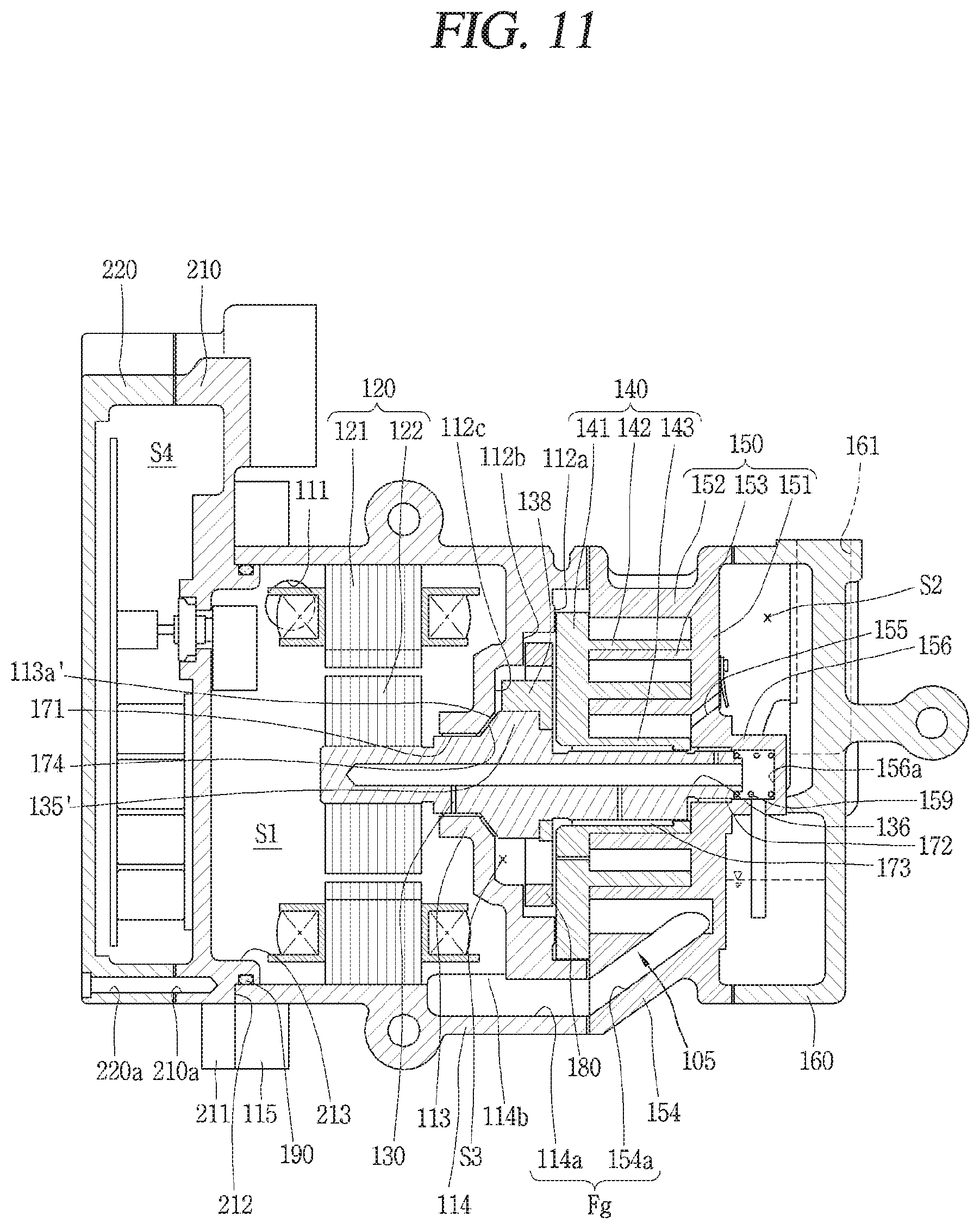
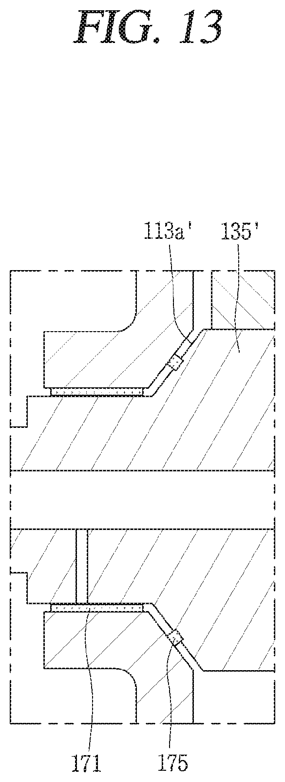
[0128] FIG. 11 is a sectional view of an inside of a motor-operated compressor according to another embodiment of the present disclosure, and FIG. 12 is a sectional view of a main housing of the motor-operated compressor according to FIG. 11. FIG. 13 is a sectional view of a main housing of a motor-operated compressor according to a variation of the embodiment of FIG. 11.
[0129] A detailed description overlapping with the foregoing embodiment will be omitted.
[0130] As aforementioned, a rotation shaft 130 is provided with a thrust portion 135' extending to a radial direction. Here, the thrust portion 135' may include an inclined surface formed to be tilted along an axial direction of the rotation shaft 130. In other words, the thrust portion 135' may be formed such that a diameter of the thrust portion 135' is gradually decreased toward a frame 112.
[0131] In addition, the frame 112 may be provided with a sealing surface 113a' formed to be tilted so as to correspond to the inclined surface. In other words, the frame 112 may be formed to correspond to the thrust portion 135' formed in an inclined manner. Accordingly, a contact area, that is, the area of the thrust surface, is increased. Thus, a sealing force between the rotation shaft 130 and the frame 112 may be further increased. Also, behavior of the rotation shaft 130 may be more stabilized as the rotation shaft 130 is axially and radially supported.
[0132] Further, according to this embodiment, a thrust bearing 174 may be disposed between the thrust surface and the sealing surface. The thrust bearing 174 may be configured as a bush bearing. In this case, the thrust bearing 174 is formed to correspond to the thrust surface. When the thrust bearing 174 is viewed from a side direction, it may be seen as a trapezoidal shape. That is, the thrust bearing may be formed to have an inner diameter and an outer diameter gradually decreasing in a direction of the frame 112.
[0133] In FIGS. 11 and 12, a frame bearing 171 and the thrust bearing 174 are made of a separate member, but unlike illustrated in the drawings, the thrust bearing 174 may be integrally formed with the frame bearing 171. That is, the frame bearing 171 is formed such that its inner and outer diameters are consistently (uniformly) extended along an axial direction from an area facing the main bearing portion 132, and its inner and outer diameters are increased to be extended from an area corresponding to the thrust surface. In this case, the area that comes into close contact with the bearing is increased, thereby increasing a sealing force of the back pressure chamber.
[0134] FIG. 13 is a sectional view of a main housing according to a modification of the embodiment of FIG. 11.
[0135] Unlike the foregoing embodiment, a sealing member 175 may be disposed on a thrust surface formed in an inclined manner. A groove may be formed in any one of the inclined surface of a thrust portion 135 and a sealing surface 113a' of a frame 112. At least a part of the sealing member 175 may be inserted into the groove.
[0136] The foregoing embodiments are merely illustrative to practice the rotary compressor according to an embodiment of the present disclosure. Therefore, the present disclosure is not limited to the above-described embodiments, and it will be understood by those of ordinary skill in the art that various changes in form and details may be made therein without departing from the scope of the present disclosure.
* * * * *
D00000
D00001
D00002
D00003
D00004
D00005
D00006
D00007
D00008
D00009
D00010
D00011
D00012

D00013
XML
uspto.report is an independent third-party trademark research tool that is not affiliated, endorsed, or sponsored by the United States Patent and Trademark Office (USPTO) or any other governmental organization. The information provided by uspto.report is based on publicly available data at the time of writing and is intended for informational purposes only.
While we strive to provide accurate and up-to-date information, we do not guarantee the accuracy, completeness, reliability, or suitability of the information displayed on this site. The use of this site is at your own risk. Any reliance you place on such information is therefore strictly at your own risk.
All official trademark data, including owner information, should be verified by visiting the official USPTO website at www.uspto.gov. This site is not intended to replace professional legal advice and should not be used as a substitute for consulting with a legal professional who is knowledgeable about trademark law.