Oil Pump
KUROKAWA; Hiroyuki ; et al.
U.S. patent application number 16/502210 was filed with the patent office on 2020-01-30 for oil pump. This patent application is currently assigned to AISIN SEIKI KABUSHIKI KAISHA. The applicant listed for this patent is AISIN SEIKI KABUSHIKI KAISHA. Invention is credited to Hiroyuki KUROKAWA, Mitsuru TERADA, Yoshito UNO.
| Application Number | 20200032789 16/502210 |
| Document ID | / |
| Family ID | 69149047 |
| Filed Date | 2020-01-30 |


View All Diagrams
| United States Patent Application | 20200032789 |
| Kind Code | A1 |
| KUROKAWA; Hiroyuki ; et al. | January 30, 2020 |
OIL PUMP
Abstract
An oil pump includes: a pump housing having a rotor accommodation space in an inner portion of the pump housing; a rotor accommodated in the rotor accommodation space; a shaft portion disposed inside the rotor; and a passage which is provided to straddle at least one of the pump housing and the rotor and the shaft portion and which communicates a pump chamber which is formed by the rotor inside the pump housing with an outside of the pump housing.
| Inventors: | KUROKAWA; Hiroyuki; (Aichi-gun, JP) ; TERADA; Mitsuru; (Okazaki-shi, JP) ; UNO; Yoshito; (Anjo-shi, JP) | ||||||||||
| Applicant: |
|
||||||||||
|---|---|---|---|---|---|---|---|---|---|---|---|
| Assignee: | AISIN SEIKI KABUSHIKI
KAISHA Kariya-shi JP |
||||||||||
| Family ID: | 69149047 | ||||||||||
| Appl. No.: | 16/502210 | ||||||||||
| Filed: | July 3, 2019 |
| Current U.S. Class: | 1/1 |
| Current CPC Class: | F04C 2210/206 20130101; F04C 2/088 20130101; F04C 13/007 20130101; F04C 2/103 20130101; F04C 2/102 20130101; F04C 2240/603 20130101 |
| International Class: | F04C 2/08 20060101 F04C002/08; F04C 2/10 20060101 F04C002/10 |
Foreign Application Data
| Date | Code | Application Number |
|---|---|---|
| Jul 25, 2018 | JP | 2018-139395 |
| Nov 19, 2018 | JP | 2018-216210 |
Claims
1. An oil pump comprising: a pump housing having a rotor accommodation space in an inner portion of the pump housing; a rotor accommodated in the rotor accommodation space; a shaft portion disposed inside the rotor; and a passage which is provided to straddle at least one of the pump housing and the rotor and the shaft portion and which communicates a pump chamber which is formed by the rotor inside the pump housing with an outside of the pump housing.
2. The oil pump according to claim 1, wherein the passage includes a first passage portion which is provided to straddle at least one of the pump housing and the rotor and the shaft portion and extends in a direction intersecting an axial direction of the shaft portion, and a second passage portion which is provided in the shaft portion and extends in the axial direction.
3. The oil pump according to claim 1, wherein the shaft portion includes an opening/closing mechanism which opens and closes the passage.
4. The oil pump according to claim 2, wherein the shaft portion includes a rotary shaft which rotationally drives the rotor, the rotary shaft includes an opening/closing mechanism which opens and closes the passage, the opening/closing mechanism includes an opening/closing valve which includes a sealing wall and a communication bore which is disposed at a position deviated in the axial direction of the rotary shaft with respect to the sealing wall and is capable of moving in the axial direction of the rotary shaft, and the opening/closing mechanism is configured to close the passage by moving to one side of the axial direction of the rotary shaft to dispose the sealing wall between the first passage portion and the second passage portion and to open the passage by moving to the other side of the axial direction of the rotary shaft to dispose, instead of the sealing wall, the communication bore between the first passage portion and the second passage portion.
5. The oil pump according to claim 4, wherein the opening/closing mechanism is configured to move the opening/closing valve according to an internal pressure of a discharging port and is configured to close the passage by disposing the sealing wall between the first passage portion and the second passage portion in a case in which the internal pressure of the discharging port is low and to open the passage by disposing, instead of the sealing wall, the communication bore between the first passage portion and the second passage portion in a case in which the internal pressure of the discharging port is high.
6. The oil pump according to claim 5, wherein the opening/closing mechanism includes a pressure chamber which is provided on one side in the axial direction of the rotary shaft of the opening/closing valve, communicates with the discharging port via a pressure passage, and pressurizes the opening/closing valve to move the opening/closing valve, a biasing member which is provided on the other side in the axial direction of the rotary shaft of the opening/closing valve and biases the opening/closing valve toward the pressure chamber, and a restriction portion which restricts movement of the opening/closing valve to the pressure chamber side, and the opening/closing mechanism is configured to close the passage by disposing the sealing wall between the first passage portion and the second passage portion in a state in which the opening/closing valve and the restriction portion are caused to abut against each other by a biasing force of the biasing member in a case in which the internal pressure of the discharging port and the pressure chamber is low and to open the passage by disposing, instead of the sealing wall, the communication bore between the first passage portion and the second passage portion in a state in which the opening/closing valve and the restriction portion are separated from each other against the biasing force of the biasing member by the internal pressure of the pressure chamber via the opening/closing valve in a case in which the internal pressure of the discharging port and the pressure chamber is high.
7. The oil pump according to claim 1, wherein the rotor is an inscribed gear rotor which includes an outer rotor including a plurality of internal teeth and an inner rotor including a plurality of external teeth which mesh with the internal teeth of the outer rotor, or the rotor is a vane rotor which includes a rotor main body and a plurality of vanes which are provided to protrude outward from the rotor main body and form the pump chamber.
8. The oil pump according to claim 1, wherein the shaft portion includes a rotary shaft which includes a recessed portion having a circular cross-section that is orthogonal to an axial direction of the shaft portion and extending in the axial direction and which rotates together with the rotor, and a fixed shaft which includes a first member which is fixed to the pump housing and a second member which is inserted into the recessed portion and is connected to the first member in a state of being capable of moving in a direction orthogonal to the axial direction.
9. The oil pump according to claim 8, wherein the fixed shaft includes a turn-stopping portion which connects the first member and the second member to each other in a state in which the second member is capable of moving in the direction orthogonal to the axial direction relative to the first member.
10. The oil pump according to claim 7, wherein the passage includes a first passage portion which is provided to straddle at least one of the pump housing and the inner rotor and the shaft portion and extending in a direction intersecting an axial direction of the shaft portion, and a second passage portion which is provided in the shaft portion and extends in the axial direction, the shaft portion includes a rotary shaft which includes a recessed portion having a circular cross-section that is orthogonal to the axial direction of the shaft portion and extends in the axial direction and which rotates together with the inner rotor, and a fixed shaft which includes a first member which is fixed to the pump housing and a second member which is inserted into the recessed portion and is connected to the first member in a state of being capable of moving in a direction orthogonal to the axial direction, and the first passage portion includes an outer passage portion which is provided to straddle the rotary shaft and the inner rotor and an inner passage portion which is provided in the fixed shaft and communicates with the outer passage portion at a predetermined rotational position of the rotary shaft.
11. The oil pump according to claim 7, wherein a tooth bottom of the inner rotor is provided with a bubble introduction portion which is disposed between the pump chamber and the passage, collects the bubbles inside the pump chamber and introduces the collected bubbles into the passage.
12. The oil pump according to claim 7, wherein the passage includes a first passage portion which is provided to straddle at least one of the pump housing and the inner rotor and the shaft portion and extends in a direction intersecting the axial direction of the shaft portion, and a second passage portion which is provided in the shaft portion and extends in the axial direction, and one end of the first passage portion is connected to a tooth bottom of the inner rotor.
13. The oil pump according to claim 2, wherein the passage is provided to straddle the pump housing and the shaft portion and the passage on the pump housing side is formed in a groove shape which communicates the pump chamber and the passage on the shaft portion side with each other.
Description
CROSS REFERENCE TO RELATED APPLICATIONS
[0001] This application is based on and claims priority under 35 U.S.C. .sctn. 119 to Japanese Patent Applications 2018-139395 and 2018-216210, filed on Jul. 25, 2018 and Nov. 19, 2018, respectively, the entire contents of which are incorporated herein by reference.
TECHNICAL FIELD
[0002] This disclosure relates to an oil pump, in particular, to an oil pump which is provided with a rotor.
BACKGROUND DISCUSSION
[0003] In the related art, an oil pump which is provided with a rotor is known (for example, refer to JP 2008-308991A (Reference 1)).
[0004] Reference 1 discloses an oil pump which is provided with an inner rotor, an outer rotor, a pump housing, a rotary shaft, and a passage for discharging bubbles. The inner rotor includes a plurality of external teeth. The outer rotor includes a plurality of internal teeth which mesh with the external teeth of the inner rotor. The pump housing houses the inner rotor and the outer rotor. The rotary shaft is disposed (inserted) in the inside of the inner rotor, the outer rotor, and the pump housing and is configured to rotate together with the inner rotor.
[0005] The passage for discharging the bubbles communicates a pump chamber between the internal teeth and the external teeth with an outside of the pump housing. The passage is provided in the pump housing at a position in the vicinity of the rotary shaft. The passage is configured to discharge the bubbles which are contained in an oil inside the pump chamber to the outside of the pump housing to remove the bubbles. The oil has a much greater specific weight than the bubbles (air). Therefore, during the driving of the oil pump, in the pump chamber, the oil is moved to the outside in a radial direction of the rotary shaft by a centrifugal force. As a result, the bubbles are gathered (moved relatively) on the inside in the radial direction of the rotary shaft (on the rotary shaft side). In other words, the bubbles are gathered on the passage side.
[0006] However, in the oil pump of Reference 1, since the passage for discharging the bubbles is provided in the pump housing at a position on the outside in the radial direction of the rotary shaft and the passage is disposed at a position which is distanced from a central axis line of rotation of the rotary shaft, even when discharging the bubbles which are gathered on the inside in the radial direction of the rotary shaft via the passage, there is an inconvenience in that a centrifugal force acts on the bubbles which are separated from the oil. As a result, there is a problem in that the bubbles (the bubbles which are contained in the oil) which are separated from the oil may not be efficiently removed.
[0007] Thus, a need exists for an oil pump which is not susceptible to the drawback mentioned above.
SUMMARY
[0008] An oil pump according to an aspect of this disclosure includes a pump housing having a rotor accommodation space in an inner portion of the pump housing, a rotor accommodated in the rotor accommodation space, a shaft portion disposed inside the rotor, and a passage which is provided to straddle at least one of the pump housing and the rotor and the shaft portion and which communicates a pump chamber which is formed by the rotor inside the pump housing with an outside of the pump housing.
BRIEF DESCRIPTION OF THE DRAWINGS
[0009] The foregoing and additional features and characteristics of this disclosure will become more apparent from the following detailed description considered with the reference to the accompanying drawings, wherein:
[0010] FIG. 1 is a view of an inscribed gear pump according to a first embodiment of the disclosure as viewed from an axial direction of a shaft portion;
[0011] FIG. 2 is a sectional diagram of the inscribed gear pump according to the first embodiment of the disclosure as viewed from an axial direction of the shaft portion;
[0012] FIG. 3 is a perspective view illustrating the shaft portion and a body of the inscribed gear pump according to the first embodiment of the disclosure;
[0013] FIG. 4 is a view illustrating the shaft portion, an inner rotor, and an outer rotor of the inscribed gear pump according to the first embodiment of the disclosure;
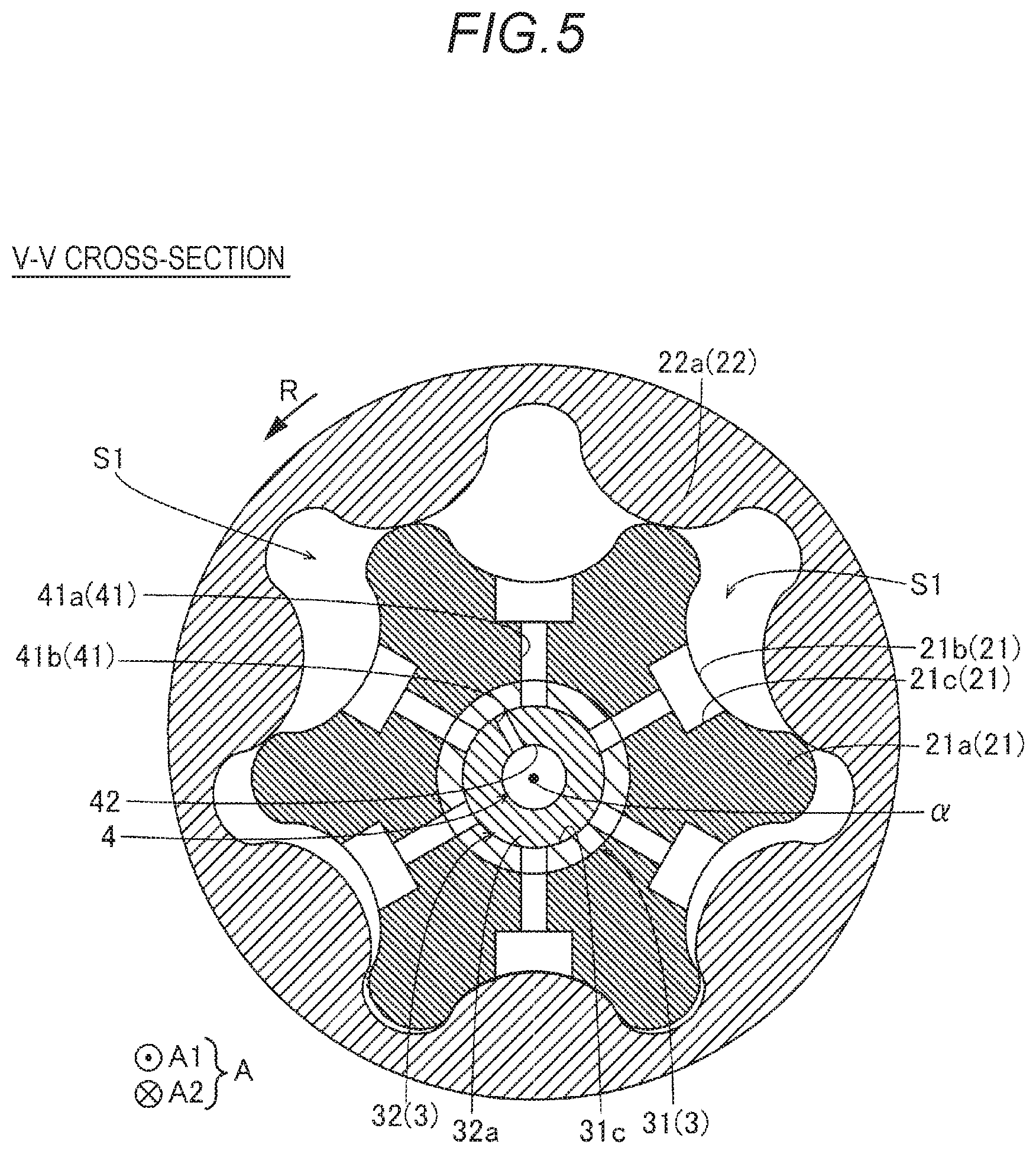
[0014] FIG. 5 is a sectional diagram taken along a V-V line of FIG. 4;
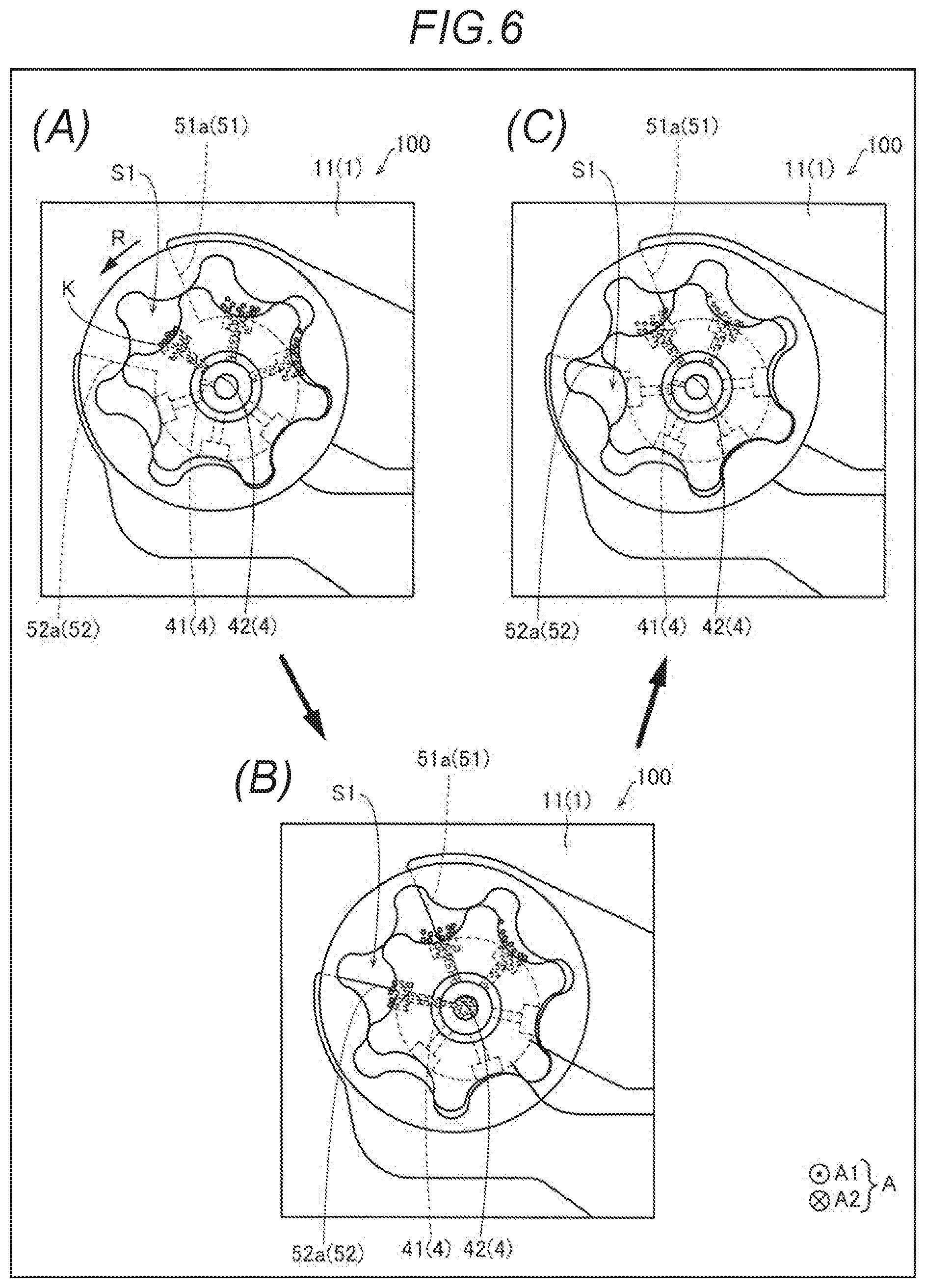
[0015] FIG. 6 is a diagram for explaining, in order, a discharging process (A) to (C) of bubbles by the inscribed gear pump according to the first embodiment of the disclosure;
[0016] FIG. 7 is a view of an inscribed gear pump according to a second embodiment of the disclosure as viewed from an axial direction of a shaft portion;
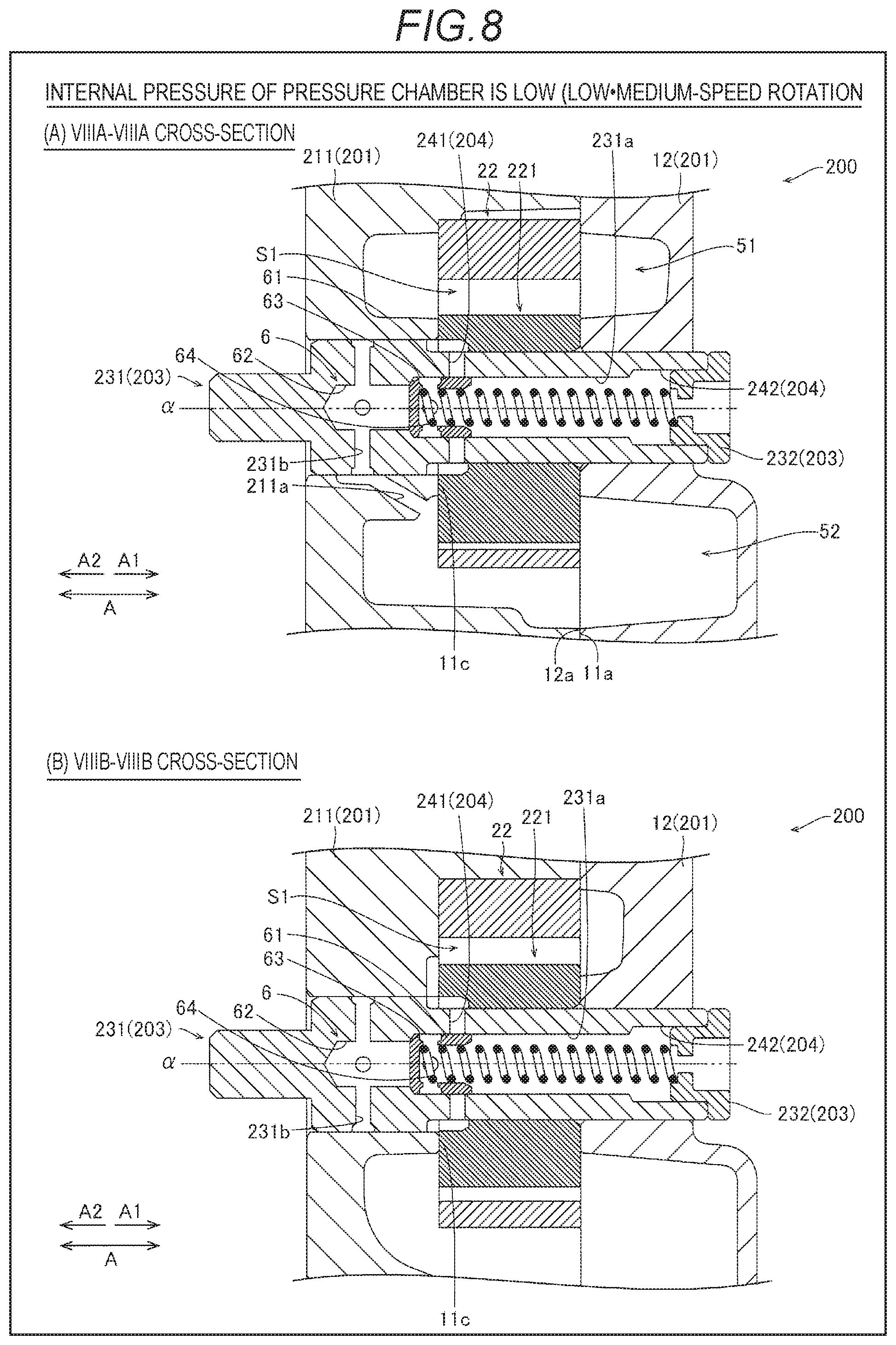
[0017] (A) in FIG. 8 is a sectional diagram of a state in which an internal pressure of a pressure chamber is low, taken along a VIIIA-VIIIA line, and (B) in FIG. 8 is a sectional diagram of a state in which the internal pressure of the pressure chamber is low, taken along a VIIIB-VIIIB line;
[0018] (A) in FIG. 9 is a sectional diagram of a state in which the internal pressure of the pressure chamber is high, taken along a VIIIA-VIIIA line, and (B) in FIG. 9 is a sectional diagram of a state in which the internal pressure of the pressure chamber is low, taken along a VIIIB-VIIIB line;
[0019] FIG. 10 is a side view illustrating an opening/closing valve of the inscribed gear pump according to the second embodiment of the disclosure;
[0020] FIG. 11 is a sectional diagram which enlarges an opening/closing mechanism of the shaft portion of the inscribed gear pump according to the second embodiment of the disclosure;
[0021] FIG. 12 is a perspective view illustrating the shaft portion and a body of the inscribed gear pump according to the second embodiment of the disclosure;
[0022] FIG. 13 is a diagram illustrating a graph for explaining the relationship between a rotation frequency of an engine and a main gallery oil pressure inside the engine;
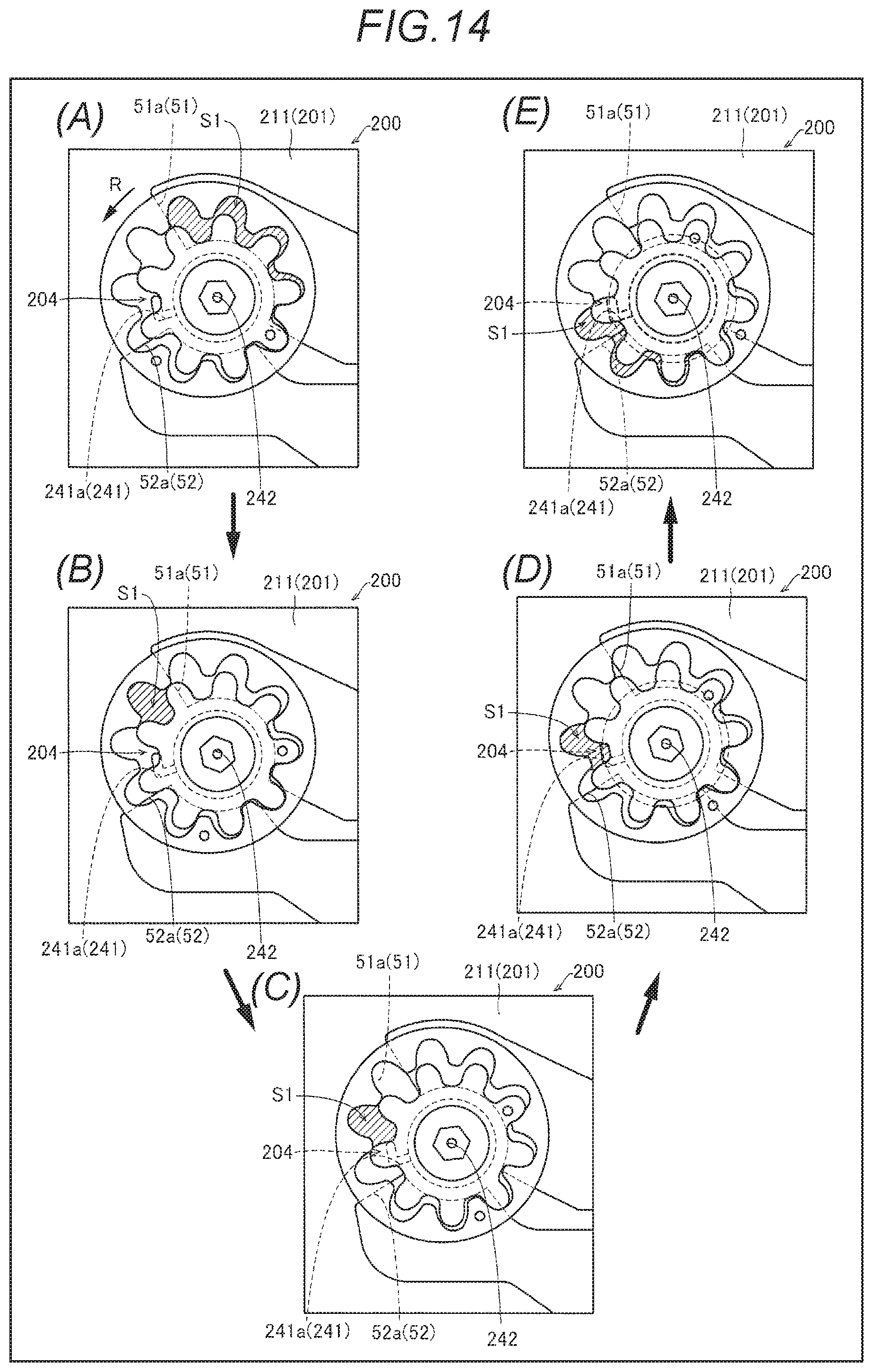
[0023] FIG. 14 is a diagram for explaining, in order, a discharging process (A) to (E) of bubbles by the inscribed gear pump according to the second embodiment of the disclosure;
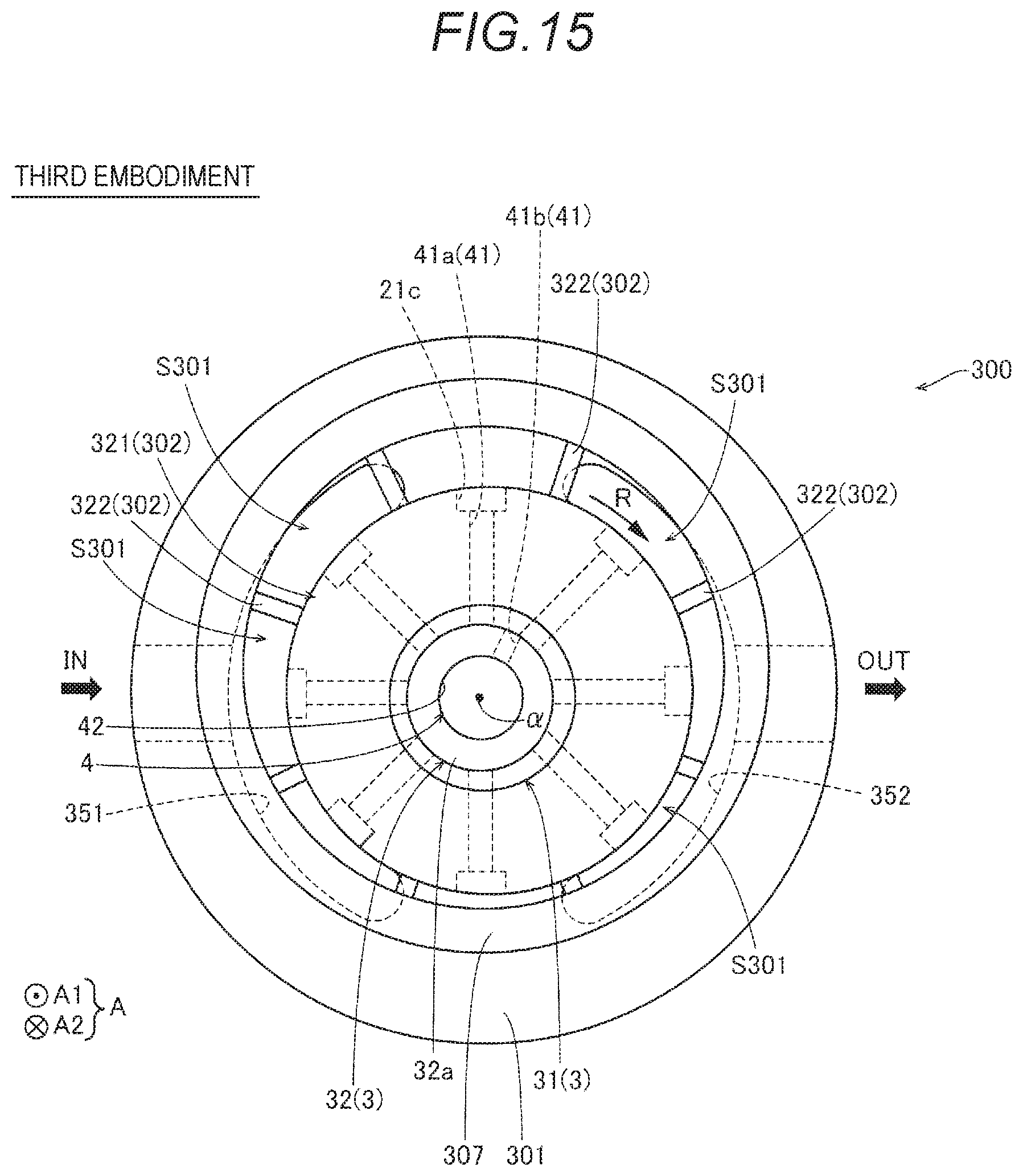
[0024] FIG. 15 is a view of a vane pump according to a third embodiment of the disclosure as viewed from an axial direction of a shaft portion;
[0025] FIG. 16 is a sectional diagram illustrating the inscribed gear pump according to a fourth embodiment of the disclosure;
[0026] FIG. 17 is an exploded perspective view illustrating a fixed shaft of the inscribed gear pump according to the fourth embodiment of the disclosure; and
[0027] FIG. 18 is a schematic diagram for explaining restriction of pivoting of a first member by a second member of the inscribed gear pump of the fourth embodiment of the disclosure.
DETAILED DESCRIPTION
[0028] Hereinafter, a description will be given of an embodiment of the disclosure based on the drawings.
First Embodiment
[0029] A description will be given of a configuration of an inscribed gear pump (an oil pump) 100 according to the first embodiment of the disclosure, with reference to FIGS. 1 to 6.
Configuration of Internally Connected Gear Pump
[0030] The inscribed gear pump 100 illustrated in FIG. 1 according to the first embodiment of the disclosure is installed in an automobile (not illustrated) which is provided with an engine. The inscribed gear pump 100 is configured to draw an oil (a lubricating oil) inside an oil pan and supply (pump) the oil to movable parts (sliding parts) such as around pistons of the engine or a crankshaft. The inscribed gear pump 100 is a trochoid pump.
[0031] The inscribed gear pump 100 is provided with a pump housing 1, an inscribed gear rotor 2 containing an inner rotor 21 including a plurality of external teeth 21a and an outer rotor 22 including a plurality of internal teeth 22a, a shaft portion 3, and a passage 4.
[0032] The inner rotor 21 and the outer rotor 22 are disposed inside the pump housing 1 in a state in which the shaft portion 3 is inserted through the inner rotor 21 and the outer rotor 22. The inner rotor 21 is configured to rotate inside the pump housing 1 according to the shaft portion 3. The outer rotor 22 is configured to rotate inside the pump housing 1 according to the shaft portion 3 via the inner rotor 21.
[0033] As illustrated in FIG. 2, in the first embodiment, the passage 4 (the configuration including a first passage portion 41 which is described later and a second passage portion 42 which is described later) is provided to span the inner rotor 21 and the shaft portion 3. The passage 4 communicates a pump chamber S1 between the internal teeth 22a (refer to FIG. 1) and the external teeth 21a (refer to FIG. 1) with the outside of the pump housing 1. The inscribed gear pump 100 is configured to discharge bubbles K (refer to FIG. 6(A)) contained in the oil inside the pump chamber S1 to the outside of the pump housing 1 via the passage 4. A detailed description will be given later.
[0034] Hereinafter, a description will be given of the detailed configuration of the parts of the inscribed gear pump 100.
Configuration of Pump Housing
[0035] As illustrated in FIG. 2, the pump housing 1 includes a body 11 and a cover 12. The body 11 and the cover 12 are positioned at one side and the other side of the axial directions of the shaft portion 3, respectively.
[0036] Hereinafter, the axial directions of the shaft portion 3 will be referred to as A directions, and of the A directions, the direction facing the cover 12 side from the body 11 side will be referred to as an A1 direction and the opposite direction will be referred to as an A2 direction.
[0037] The body 11 and the cover 12 are assembled in a state in which an abutting surface 11a and an abutting surface 12a which extend in directions orthogonal to the A directions abut against each other. The body 11 and the cover 12 include through holes 11b and 12b, respectively, on the same axis which extends in the A directions. The shaft portion 3 is inserted through the through holes 11b and 12b.
[0038] An inner portion of the pump housing 1 includes a rotor accommodation space S2 which accommodates the inner rotor 21 and the outer rotor 22. In detail, the body 11 includes a recessed portion which is recessed in the A2 direction from the abutting surface 11a. The body 11 and the cover 12 form the rotor accommodation space S2 by blocking the recessed portion of the body 11 with the cover 12.
[0039] The thickness directions of the rotor accommodation space S2 are the A directions, and the rotor accommodation space S2 has a circular column shape corresponding to the external shape of the outer rotor 22. The inner rotor 21 and the outer rotor 22 have approximately the same thickness in the A directions.
[0040] Therefore, the inner rotor 21 and the outer rotor 22 are configured to cause the A2 direction end surfaces thereof to slide on the body 11 and to cause the A1 direction end surfaces to slide on the cover 12. In other words, the body 11 includes a sliding surface 11c on a bottom portion of the recessed portion (the A2 direction side of the rotor accommodation space S2). The cover 12 includes a sliding surface on the A1 direction side of the rotor accommodation space S2. The sliding surface of the cover 12 is positioned on the same plane as the abutting surface 12a and is a surface which continues from the abutting surface 12a (that is, the sliding surface of the cover 12 and the abutting surface 12a are the same surface).
[0041] As illustrated in FIG. 1, a suction port 51 and a discharging port 52 are formed in the pump housing 1.
[0042] The suction port 51 functions as an introduction path which guides the oil which is sucked into the apparatus to the pump chamber S1. The discharging port 52 functions as an outlet path which guides the oil inside the pump chamber S1 to the outside of the apparatus. The suction port 51 and the discharging port 52 are provided to span the body 11 and the cover 12 together. The suction port 51 and the discharging port 52 are provided together to be adjacent to the pump chamber S1. The suction port 51 and the discharging port 52 are not directly continuous with each other and are provided at angular positions in the circumferential direction (the rotation direction) of the shaft portion 3 so as not to overlap each other.
[0043] As illustrated in FIG. 3, the suction port 51 and the discharging port 52 of the body 11 side are both formed in a recessed shape which is more depressed to the A2 direction side than the sliding surface 11c. The suction port 51 and the discharging port 52 of the cover 12 side are both formed in a recessed shape which is more depressed to the A1 direction side than the abutting surface 12a.
[0044] As illustrated in FIG. 1, the suction port 51 is connected to the oil pan (not illustrated) which is positioned on the upstream side of the suction port 51 and is a supply source of the oil. The suction port 51 includes an opening 51a which communicates with the pump chamber S1 in a portion of the suction port 51 at which the pump chamber S1 expands. The opening 51a functions as an inflow port in which the oil flows into the pump chamber S1 from inside the suction port 51.
[0045] The discharging port 52 is connected to engine parts (not illustrated) which are positioned on the downstream side of the discharging port 52 and are the oil supply destination. The discharging port 52 includes an opening 52a which communicates with the pump chamber S1 in a portion of the discharging port 52 at which the pump chamber S1 contracts. The opening 52a functions as an outflow port in which the oil flows out from the pump chamber S1 into the discharging port 52.
Configuration of Inner Rotor and Outer Rotor
[0046] As illustrated in FIG. 1, the external teeth 21a of the inner rotor 21 are disposed on the inside of the outer rotor 22 to mesh, from the inside, with the internal teeth 22a of the outer rotor 22. The outer rotor 22 is accommodated in the rotor accommodation space S2. The number of the external teeth 21a of the inner rotor 21 is one tooth less than the number of the internal teeth 22a of the outer rotor 22.
[0047] The inner rotor 21 is configured to be rotated by the shaft portion 3 (a rotary shaft 31 which is described later) which is disposed on the inside. The inner rotor 21 (the shaft portion 3) is configured to rotate around a central axis line of rotation .alpha. which is eccentric with respect to the central axis line of rotation of the outer rotor 22.
[0048] When the inner rotor 21 is rotated in an arrow R direction, the outer rotor 22 is rotated in the same direction. During the rotation, the external teeth 21a of the inner rotor 21 and the internal teeth 22a of the outer rotor 22 mesh with each other on the side at which the distance between the inner rotor 21 and the outer rotor 22 is small, and since the external teeth 21a are fewer by one tooth than the internal teeth 22a on the side at which the distance is great, the external teeth 21a and the internal teeth 22a do not mesh with each other and a gap (the pump chamber S1) between the external teeth 21a and the internal teeth 22a is formed.
[0049] The inner rotor 21 and the outer rotor 22 produce a pump function by causing the pump chamber S1 to rotationally move in the arrow R direction to expand and contract the pump chamber S1. Therefore, as the volume of the pump chamber S1 expands, the oil flows from the suction port 51 into the pump chamber S1. As the volume of the pump chamber S1 contracts, the oil flows out from the pump chamber S1 to the discharging port 52.
[0050] A bubble introduction portion 21c is provided in each of the plurality of (six) tooth bottoms 21b of the inner rotor 21. The bubble introduction portion 21c has a recessed shape which is depressed to the inside in the radial direction of the shaft portion 3. The passage 4 (an outer passage portion 41a of the first passage portion 41 which is described later) is connected to the bubble introduction portion 21c from the inside in the radial direction of the shaft portion 3. The bubble introduction portion 21c is disposed between the pump chamber S1 and the passage 4. The bubble introduction portion 21c is configured to collect the bubbles K of the pump chamber S1 and introduce the collected bubbles K into the passage 4.
Configuration of Shaft Portion
[0051] As illustrated in FIG. 2, the shaft portion 3 includes the rotary shaft 31 and a fixed shaft 32. The rotary shaft 31 is attached to the pump housing 1 from the A2 direction side to be capable of rotating. Meanwhile, the fixed shaft 32 is attached in a fixed manner to the pump housing 1 (the cover 12) from the A1 direction side.
[0052] The rotary shaft 31 has a circular column shape, substantially extending in the A directions. The rotary shaft 31 includes a belt attaching portion 31a to which a belt B is attached at an end portion in the A2 direction. The rotary shaft 31 is configured to rotationally drive the inner rotor 21 by receiving a rotational driving force (torque) from a crankshaft or the like via the belt B and rotationally driving. The rotary shaft 31 is inserted through (fitted into) the inner rotor 21 by press-fitting and rotates in synchronization with the inner rotor 21.
[0053] The rotary shaft 31 includes a positioning surface 31b which abuts against the A2 direction end surface of the inner rotor 21 to position the rotary shaft 31 in the A directions. The positioning surface 31b is positioned on substantially the same plane as the sliding surface 11c of the body 11. The positioning surface 31b is formed by a level difference which reduces the size of the inner diameter of the rotary shaft 31 on the A1 direction side.
[0054] The rotary shaft 31 is also inserted through the through hole 12b such that the end portion of the rotary shaft 31 on the A1 direction side is disposed inside the through hole 12b of the cover 12. The rotary shaft 31 extends from the body 11 side in the A1 direction to a middle position in the thickness directions (the A directions) of the cover 12. A recessed portion 31c which is depressed in the A2 direction is formed in the end surface of the rotary shaft 31 on the A1 direction side. The recessed portion 31c has a circular column shape in a cross-section orthogonal to the A directions. The central axis line of the recessed portion 31c is positioned on substantially the same axis as the central axis line of rotation .alpha. of the rotary shaft 31. A bottom portion 31d of the recessed portion 31c on the A2 direction side is positioned closer to the A2 direction side than the inner rotor 21.
[0055] The fixed shaft 32 is disposed inside the rotary shaft 31 excluding a portion of the fixed shaft 32 on the A1 direction side. The fixed shaft 32 is provided with an inner passage portion 41b of the first passage portion 41 (described later) of the passage 4 and the second passage portion 42 (described later) of the passage 4.
[0056] The fixed shaft 32 includes a fixed shaft main body 32a and a fixed shaft attaching portion 32b.
[0057] The fixed shaft main body 32a has a circular column shape (a cylindrical shape) extending in the A directions. The fixed shaft main body 32a is inserted into the recessed portion 31c of the fixed shaft main body 32a (is fitted into the recessed portion 31c) from the A1 direction side. Therefore, the central axis line of the fixed shaft main body 32a is positioned on substantially the same axis as the central axis line of rotation .alpha. of the rotary shaft 31. The fixed shaft main body 32a extends from the cover 12 side in the A2 direction to a position in the vicinity of the A2 direction side end surface (the sliding surface 11c of the body 11) of the inner rotor 21.
[0058] As illustrated in FIG. 4, the fixed shaft attaching portion 32b has a flat plate shape which extends along the outer surface of the A1 direction side of the cover 12 (refer to FIG. 1). The fixed shaft attaching portion 32b includes a pin mounting hole 320a and a bolt mounting hole 320b. A positioning pin for restricting the rotation of the fixed shaft 32 with respect to the cover 12 is mounted to the pin mounting hole 320a and a bolt for fixing the fixed shaft 32 to the cover 12 is mounted to the bolt mounting hole 320b.
[0059] As illustrated in FIG. 2, the fixed shaft attaching portion 32b is provided with a protruding portion 323 which protrudes in the A2 direction and is fitted into the through hole 12b of the cover 12.
[0060] A lubrication chamber 33 is formed between an end surface of the fixed shaft main body 32a on the A2 direction side and the bottom portion 31d of the recessed portion 31c of the rotary shaft 31. The lubrication chamber 33 is adjacent to the inner surface of the recessed portion 31c of the rotary shaft 31 and the outer surface of the fixed shaft main body 32a which slide against each other during the rotation of the rotary shaft 31, and the lubrication chamber 33 is configured to supply the oil inside the lubrication chamber 33 to the surfaces which slide against each other.
[0061] A lubrication chamber 34 is formed between the end surface of the rotary shaft 31 on the A1 direction side and the protruding portion 323 of the fixed shaft 32. The lubrication chamber 34 is adjacent to the outer surface of the rotary shaft 31 and the inner surface of the through hole 12b of the cover 12 which slide against each other during the rotation of the rotary shaft 31, and the lubrication chamber 34 is configured to supply the oil inside the lubrication chamber 34 to the surfaces which slide against each other.
Configuration of Passage
[0062] The passage 4 is provided to span the inner rotor 21 and the shaft portion 3 as described above. The passage 4 includes the first passage portion 41 and the second passage portion 42.
[0063] As illustrated in FIG. 5, the first passage portion 41 extends in directions which intersect (directions which are orthogonal to) the axial directions (the A directions) of the shaft portion 3. FIG. 5 illustrates a cross-section which is orthogonal to the A directions at a middle position of the inner rotor 21 in the A directions. In detail, the first passage portion 41 extends in the radial direction of the shaft portion 3. The first passage portion 41 is disposed at a middle position of the inner rotor 21 in the thickness directions. The first passage portion 41 includes a plurality of (six) outer passage portion 41a and the single inner passage portion 41b.
[0064] The outer passage portion 41a is formed by a through hole which is provided in the inner rotor 21. The outer passage portion 41a is disposed closer to the outside than the inner passage portion 41b in the radial direction of the shaft portion 3. The outer passage portion 41a is provided to span the inner rotor 21 and the rotary shaft 31. Therefore, the outer passage portion 41a rotates in synchronization with the inner rotor 21 and the rotary shaft 31.
[0065] One end on the outside of the outer passage portion 41a is connected to the tooth bottoms 21b (the pump chamber S1) of the inner rotor 21 via the bubble introduction portion 21c. The other end on the inside of the outer passage portion 41a is connected to the recessed portion 31c of the rotary shaft 31. Therefore, the outer passage portion 41a communicates the pump chamber S1 with the inside of the recessed portion 31c of the rotary shaft 31.
[0066] The plurality of outer passage portions 41a are disposed at the same position from each other in the A directions. The plurality of outer passage portions 41a are disposed at an equal angular interval in the circumferential direction (the rotation direction) of the shaft portion 3. The plurality of outer passage portions 41a extend both linearly and radially in the radial direction of the shaft portion 3.
[0067] The inner passage portion 41b is formed using a through hole which is provided in the fixed shaft 32. Therefore, even if the inner rotor 21 and the shaft portion 3 rotate, the inner passage portion 41b does not rotate. One end on the outside of the inner passage portion 41b is connected to the outside surface of the fixed shaft 32. The other end on the inside of the inner passage portion 41b is connected to the second passage portion 42 on the inside of the fixed shaft 32. The inner passage portion 41b has a smaller diameter (the diameter in a cross-section orthogonal to the directions in which the inner passage portion 41b extends) than the outer passage portion 41a.
[0068] The inner passage portion 41b extends linearly in the radial direction of the shaft portion 3. The inner passage portion 41b is disposed at a position (refer to FIG. 2) corresponding to the outer passage portion 41a in the A directions so as to communicate with the outer passage portion 41a at a predetermined rotational position of the rotary shaft 31 during the rotation of the inner rotor 21 and the rotary shaft 31 (during the rotation of the outer passage portion 41a).
[0069] As illustrated in FIG. 1, the inner passage portion 41b faces the discharging port 52 side more than the suction port 51 side. In detail, the inner passage portion 41b is disposed closer to the discharging port 52 side than a middle position (the dot-dash line of FIG. 1) between the end portion of the suction port 51 (the opening 51a) and the end portion of the discharging port 52 (the opening 52a) on the side at which the distance between the inner rotor 21 and the outer rotor 22 increases. In other words, the inner passage portion 41b is configured to communicate with the pump chamber S1 via the outer passage portion 41a at a later point than the timing at which the volume of the pump chamber S1 reaches the maximum. The discharging port 52 (the opening 52a) is also configured to communicate with the pump chamber S1 at a later point than the timing at which the volume of the pump chamber S1 reaches the maximum.
[0070] The second passage portion 42 is formed using a through hole which is provided in the fixed shaft 32 of the shaft portion 3. The second passage portion 42 extends in the axial directions (the A directions) along the central axis line of rotation .alpha. of the rotary shaft 31 of the shaft portion 3. The central axis line of the second passage portion 42 is positioned on substantially the same axis as the central axis line of rotation .alpha. of the rotary shaft 31.
[0071] One end of the second passage portion 42 on the A1 direction side is connected to the outer surface (the outside) of the pump housing 1. In other words, one end of the second passage portion 42 on the A1 direction side is connected to the atmosphere. The other end of the second passage portion 42 on the A2 direction side is connected to the lubrication chamber 33. The second passage portion 42 is provided with a lateral hole 42a which is connected to the lubrication chamber 34 and extends in a direction which intersects the A directions. Therefore, the passage 4 is configured to supply the oil which flows out in tiny amounts from the pump chamber S1 to the lubrication chamber 33 and the lubrication chamber 34 during the discharging of the bubbles K.
Discharging Operation of Bubbles
[0072] Next a description will be given of the discharging operation of the bubbles K from the pump chamber S1 via the passage 4 of the inscribed gear pump 100 with reference to FIG. 6(A) to 6(C).
[0073] First, as illustrated in FIG. 6(A), the communication between the suction port 51 and the pump chamber S1 is shut off in a state in which the oil is supplied into the pump chamber S1 via the opening 51a of the suction port 51. In this state, the pump chamber S1 does not communicate with any of the suction port 51, the discharging port 52, and the passage 4.
[0074] When the pump chamber S1 rotates in the arrow R direction from the state of FIG. 6(A), the pump chamber S1 becomes the maximum volume and assumes the state of FIG. 6(B) while contracting from the maximum volume. In the state of FIG. 6(B), the pump chamber S1 communicates with the outside of the pump housing 1 via the passage 4. In other words, the first passage portion 41 and the second passage portion 42 communicate with each other and the passage 4 assumes a state of being capable of discharging the bubbles K.
[0075] When the pump chamber S1 rotates in the arrow R direction from the state of FIG. 6(B), the pump chamber S1 assumes the state of FIG. 6(C). In the state of FIG. 6(C), the pump chamber S1 and the discharging port 52 communicate with each other and the communication between the first passage portion 41 and the second passage portion 42 is nullified. In other words, the inscribed gear pump 100 assumes a state in which it is possible to discharge, to the engine parts (not illustrated) via the discharging port 52, the oil in which the discharging of the bubbles K from the pump chamber S1 via the passage 4 is completed and which does not substantially contain the bubbles K. Hereinabove, the series of operations for discharging the bubbles K from the pump chamber S1 is completed.
Effects of First Embodiment
[0076] In the first embodiment, it is possible to obtain the following effects.
[0077] In the first embodiment, as described above, by providing the passage 4 to straddle the shaft portion 3 which is disposed on the inside of the inscribed gear rotor 2 (the inner rotor 21), it is possible to dispose the passage 4 at a closer position to the central axis line of rotation of the inscribed gear rotor 2 (the inner rotor 21) as compared to a case in which the passage 4 is provided in the pump housing 1. In other words, since it is possible to ensure that a centrifugal force does not substantially act on the bubbles which are separated from the oil by a centrifugal force and gathered on the passage 4 side, it is possible to efficiently discharge the bubbles which are separated from the oil via the passage 4. As a result, it is possible to efficiently remove the bubbles K contained in the oil via the passage 4.
[0078] In the first embodiment, as described above, the passage 4 includes the first passage portion 41 which is provided to straddle the inscribed gear rotor 2 (the inner rotor 21) and the shaft portion 3 and extends in a direction intersecting the axial directions of the shaft portion 3, and the second passage portion 42 which is provided in the shaft portion 3 and extends in the axial directions. Accordingly, it is possible to easily move the bubbles K to the shaft portion 3 side using the first passage portion 41 and it is possible to easily discharge and remove the bubbles K which are moved to the shaft portion 3 side by the first passage portion 41 to the outside of the pump housing 1 using the second passage portion 42.
[0079] In the first embodiment, as described above, the inscribed gear rotor 2 which includes the outer rotor 22 and the inner rotor 21, the outer rotor 22 including the plurality of internal teeth 22a and the inner rotor 21 including the plurality of external teeth 21a which engage with the internal teeth 22a of the outer rotor 22 is used. Accordingly, it is possible to obtain a great output using a comparatively small structure according to the inscribed gear rotor 2.
Second Embodiment
[0080] Next, a description will be given of the second embodiment with reference to FIGS. 7 to 14. In the second embodiment, unlike the first embodiment in which the passage 4 for discharging the bubbles is provided to straddle only the inner rotor 21 and the shaft portion 3, a description will be given of an example in which a passage 204 for discharging the bubbles is provided to straddle a pump housing 201 in addition to an inner rotor 221 and a shaft portion 203. In the second embodiment, a description will be given of an example in which the shaft portion 203 includes an opening/closing mechanism 6 of the passage 204 in addition to the configuration of the first embodiment. In the figures, configurations that are the same as those of the first embodiment are depicted with the same reference numerals as in the first embodiment.
[0081] As illustrated in FIG. 7, an inscribed gear pump (an oil pump) 200 in the second embodiment of the disclosure includes the pump housing 201, an inscribed gear rotor (the rotor) 202, the shaft portion 203, and the passage 204. The inscribed gear rotor 202 contains the inner rotor 221 which includes the plurality of external teeth 21a, and the outer rotor 22 which includes the plurality of internal teeth 22a.
Configuration of Pump Housing
[0082] As illustrated in (A) and (B) in FIG. 8, the pump housing 201 includes a body 211 and the cover 12. (A) and (B) in FIG. 8 illustrate different states of the pump housing 201 from those of (A) and (B) in FIG. 9. In detail, (A) and (B) in FIG. 8 illustrate a state in which the passage 204 is closed by the opening/closing mechanism 6 (described later), and (A) and (B) in FIG. 9 illustrate a state in which the passage 204 is opened by the opening/closing mechanism 6.
[0083] The body 211 includes a pressure passage 211a which supplies the oil to a pressure chamber 62 which is provided on the inside of a rotary shaft 231 (described later) from the discharging port 52. In other words, the discharging port 52 and the pressure chamber 62 communicate with each other via the pressure passage 211a. Therefore, the rotation frequency (the rotation speed) of the rotary shaft 231 (described later) of the shaft portion 203 increases due to an increase in the rotation frequency of the engine and the internal pressure of the pressure chamber 62 also increases due to an increase in the internal pressure of the discharging port 52.
Configuration of Inner Rotor
[0084] As illustrated in FIG. 7, the bubble introduction portion 21c and the through hole (the inner passage portion 41b) are not provided in the inner rotor 221 as they are in the first embodiment. The inner rotor 221 is provided with a groove-shaped rotor-side passage portion 241b which forms a portion of the passage 204 (a first passage portion 241 which is described later). A detailed description will be given later.
Configuration of Shaft Portion
[0085] As illustrated in (A) and (B) in FIG. 8, the shaft portion 203 includes the rotary shaft 231, the opening/closing mechanism 6 which is provided on the rotary shaft 231 and opens and closes the passage 204, and a plug 232 which is provided on the rotary shaft 231.
[0086] A recessed portion 231a which is depressed in the A2 direction is formed in the end surface of the rotary shaft 231 on the A1 direction side. The recessed portion 231a has a circular column shape in a cross-section orthogonal to the A directions. The central axis line of the recessed portion 231a is positioned on substantially the same axis as the central axis line of rotation .alpha. of the rotary shaft 231. A bottom portion of the recessed portion 231a on the A2 direction side is positioned closer to the A2 direction side than the inner rotor 221 (the sliding surface 11c of the body 211).
Configuration of Open-Close Mechanism of Shaft Portion
[0087] As illustrated in (A) and (B) in FIG. 8, the opening/closing mechanism 6 is disposed inside the recessed portion 231a. The opening/closing mechanism 6 includes an opening/closing valve 61, the pressure chamber 62, a restriction portion 63, and a compressed coil spring (a biasing member) 64.
[0088] The opening/closing valve 61 has a hollow shape in which the A1 direction side is open. The opening/closing valve 61 has a substantially circular column outside shape. In a state in which the opening/closing valve 61 is disposed inside the recessed portion 231a, the opening/closing valve 61 partitions the inside space of the recessed portion 231a into two spaces, a space (the pressure chamber 62) on the A2 direction side of the opening/closing valve 61 and a space (a second passage portion 242 which is described later) on the A1 direction side of the opening/closing valve 61. The opening/closing valve 61 performs the partitioning of the two spaces such that there is no (substantially no) exchanging of the oil between the two spaces.
[0089] The opening/closing valve 61 is configured to be capable of moving in the axial directions (the A directions) of the rotary shaft 231. In detail, the opening/closing valve 61 is configured to be capable of reciprocal movement in a predetermined area in the A directions within the rotary shaft 231 according to the internal pressure of the pressure chamber 62 (the discharging port 52).
[0090] The pressure chamber 62 is provided adjacent to the rotary shaft 231 of the opening/closing valve 61 on one side (the A2 direction side) of the axial directions of the rotary shaft 231. As described above, the pressure chamber 62 communicates with the discharging port 52 via the pressure passage 211a of the body 211. The pressure chamber 62 is configured to pressurize the opening/closing valve 61 in the A1 direction in accordance with a fluctuation in the internal pressure of the pressure chamber 62 to move the opening/closing valve 61 in the A1 direction against the biasing force of the compressed coil spring 64. The opening/closing valve 61 separates from the restriction portion 63 when the opening/closing valve 61 moves in the A1 direction.
[0091] As illustrated in (A) in FIG. 8, the rotary shaft 231 is provided with a pressure passage 231b which communicates the pressure chamber 62 with the pressure passage 211a of the body 211. The pressure passage 231b includes an annular groove which has an annular shape extending along the outside surface of the rotary shaft 231 to surround the rotary shaft 231, and a through hole which extends from the annular groove to the inside of the shaft portion 203 in the radial directions to communicate with the pressure chamber 62.
[0092] The restriction portion 63 is formed on the inside surface of the recessed portion 231a. In detail, the restriction portion 63 is formed by a level difference which reduces the size of the inner diameter of the recessed portion 231a on the A2 direction side. The restriction portion 63 is positioned closer to the A2 direction side than the inner rotor 221 (the sliding surface 11c of the body 211). The restriction portion 63 is configured to restrict the movement of the opening/closing valve 61 to the pressure chamber 62 side by abutting against the opening/closing valve 61. In other words, the opening/closing valve 61 does not move further to the A2 direction side than a position at which the opening/closing valve 61 abuts against the restriction portion 63.
[0093] The compressed coil spring 64 is provided adjacent to the rotary shaft 231 of the opening/closing valve 61 on the other side (the A1 direction side) in the axial directions of the rotary shaft 231 and is configured to bias the opening/closing valve 61 toward the pressure chamber 62 (the restriction portion 63).
[0094] The plug 232 supports the A1 direction end portion of the compressed coil spring 64. The plug 232 is attached to the A2 direction end portion of the recessed portion 231a of the rotary shaft 231 using fitting (including screwing). The plug 232 has a through hole which penetrates the plug 232 in the A directions.
[0095] As illustrated in FIGS. 10 and 11, the opening/closing valve 61 includes a sealing wall 61a and a communication bore 61b.
[0096] The sealing wall 61a is a wall portion which extends along the inner surface of the recessed portion 231a of the rotary shaft 231. The sealing wall 61a has a function of sealing the passage 204 in the middle so as not to discharge the bubbles to the outside of the pump housing 201. The sealing wall 61a is disposed between the first passage portion 241 and the second passage portion 242 and closes the passage 204 (ensures that the bubbles may not be discharged) in a state (refer to (A) and (B) in FIG. 8) in which the opening/closing valve 61 abuts against the restriction portion 63.
[0097] The communication bore 61b is disposed at a position which deviates in an axial direction (the A2 direction) of the rotary shaft 231 with respect to the sealing wall 61a. A plurality (four) of the communication bores 61b are provided. The plurality of communication bores 61b are disposed at an equal angular interval in the circumferential direction (the rotation direction) of the shaft portion 203. The plurality of communication bores 61b extend both linearly and radially in the radial direction of the shaft portion 203. The communication bores 61b have a function of communicating with the passage 204 in order to discharge the bubbles to the outside of the pump housing 201. An annular groove which has an annular shape extending along the inner surface of the recessed portion 231a to surround the opening/closing valve 61 is provided in the outside end portion of the communication bores 61b.
[0098] The communication bore 61b is disposed between the first passage portion 241 and the second passage portion 242 and opens the passage 204 (ensures that the bubbles may be discharged) in a state (a state in which the rotation frequency of the engine increases and the internal pressure of the discharging port 52 and the pressure chamber 62 is increased) (refer to (A) and (B) in FIG. 9) in which the opening/closing valve 61 moves in the A2 direction against the biasing force of the compressed coil spring 64 and the opening/closing valve 61 separates from the restriction portion 63 by a predetermined distance.
Configuration of Passage
[0099] As illustrated in FIG. 11, the passage 204 is provided to straddle the body 211 of the pump housing 201, the inner rotor 21, and the shaft portion 203 as described above. The passage 204 includes the first passage portion 241 and the second passage portion 242.
[0100] The first passage portion 241 is provided to straddle the body 211, the inner rotor 221, and the shaft portion 203.
[0101] The first passage portion 241 includes a body-side passage portion 241a which is provided in the body 211, a rotor-side passage portion 241b which is provided in the inner rotor 221, and a shaft portion-side first passage portion 241c and a shaft portion-side second passage portion 241d which are provided in the shaft portion 203.
[0102] The rotor-side passage portion 241b, the shaft portion-side first passage portion 241c, and the shaft portion-side second passage portion 241d rotate in synchronization with the inner rotor 221 and the rotary shaft 231. Meanwhile, the body-side passage portion 241a does not rotate in synchronization with the inner rotor 221 and the rotary shaft 231. The shaft portion-side second passage portion 241d, the rotor-side passage portion 241b, the shaft portion-side first passage portion 241c, and the body-side passage portion 241a are disposed in order from the downstream side (the atmosphere side) (the second passage portion 242 side) at which the bubbles are discharged.
[0103] As illustrated in FIG. 12, the body-side passage portion 241a is provided in the sliding surface 11c of the body 211. The body-side passage portion 241a has a letter L shape as viewed from the A directions and is formed in a groove shape which is depressed in the A2 direction from the sliding surface 11c. Therefore, the body-side passage portion 241a extends in a direction which intersects (a direction which are orthogonal to) the axial directions (the A directions) of the shaft portion 203.
[0104] As illustrated in FIG. 7, one end on the outside (the outside of the shaft portion 203 in the radial direction) of the body-side passage portion 241a is disposed at a position (a position in the vicinity of the tooth bottoms 21b) at which the body-side passage portion 241a communicates with the space between adjacent external teeth 21a in the pump chamber S1 when the inner rotor 221 rotates. The other end on the inside (the inside in the radial direction of the shaft portion 203) of the body-side passage portion 241a is connected to the rotor-side passage portion 241b and the shaft portion-side first passage portion 241c. In other words, the body-side passage portion 241a communicates the pump chamber S1 with the rotor-side passage portion 241b and the shaft portion-side first passage portion 241c (the shaft portion-side second passage portion 241d).
[0105] As illustrated in FIG. 11, the rotor-side passage portion 241b is provided in the A2 direction end portion on the inner peripheral side of the inner rotor 221. The rotor-side passage portion 241b is formed in an annular groove shape which extends to surround the shaft portion 203.
[0106] The shaft portion-side first passage portion 241c is disposed substantially adjacent to the rotor-side passage portion 241b on the A2 direction side. The shaft portion-side first passage portion 241c is formed by a level difference which reduces the size of the outer diameter of the rotary shaft 231 on the A1 direction side. The shaft portion-side first passage portion 241c is formed in an annular shape which extends to surround the shaft portion 203. The shaft portion-side first passage portion 241c is disposed substantially at a position corresponding to the body-side passage portion 241a in the A directions. The shaft portion-side first passage portion 241c and the rotor-side passage portion 241b form an annular space which surrounds the opening/closing valve 61.
[0107] The shaft portion-side second passage portion 241d is formed by a through hole which is provided in the rotary shaft 231 and extends in the radial direction of the shaft portion 203. A plurality (four) of the shaft portion-side second passage portions 241d are provided. The plurality of shaft portion-side second passage portions 241d are disposed at an equal angular interval in the circumferential direction (the rotation direction) of the shaft portion 203. The plurality of shaft portion-side second passage portions 241d are disposed substantially at positions corresponding to the rotor-side passage portion 241b in the A directions.
[0108] The second passage portion 242 is formed to extend in the A directions by the inner portion space of the opening/closing valve 61, the inner portion space of the recessed portion 231a, and the through hole of the plug 232 (refer to FIG. 7).
[0109] One end of the second passage portion 242 on the A1 direction side is connected to the outer surface (the outside) of the pump housing 201. In other words, one end of the second passage portion 242 on the A1 direction side is connected to the atmosphere. The vicinity of the other end of the second passage portion 242 on the A2 direction side is connected to the first passage portion 241 in a state (a state in which the internal pressure of the pressure chamber 62 is high) in which the opening/closing valve 61 is separated from the restriction portion 63.
Operation of Open-Close Mechanism
[0110] A description will be given of the operations of the opening/closing mechanism 6 with reference to (A) and (B) in FIG. 8 and (A) and (B) in FIG. 9.
[0111] The opening/closing mechanism 6 is configured to open and close the passage 204 by causing the opening/closing valve 61 to move reciprocally in the A directions. (A) and (B) in FIG. 8 illustrate a state in which the passage 204 is closed (a state in which the opening/closing valve 61 moves to the A2 direction side). Meanwhile, (A) and (B) in FIG. 9 illustrate a state in which the passage 204 is open (a state in which the opening/closing valve 61 moves to the A1 direction side). Hereinafter, a description will be given of the open state and the closed state of the passage 204, in order.
[0112] As illustrated in (A) and (B) in FIG. 8, in a case in which the internal pressure of the discharging port 52 and the pressure chamber 62 is low, the opening/closing mechanism 6 is configured such that the sealing wall 61a is disposed between the first passage portion 241 and the second passage portion 242 in a state in which the opening/closing valve 61 and the restriction portion 63 abut against each other due to the biasing force of the compressed coil spring 64. Accordingly, the opening/closing mechanism 6 is configured to close the passage 204. A case in which the internal pressure of the discharging port 52 and the pressure chamber 62 is low is a case in which the rotation frequency (the rotational speed) of the rotary shaft 231 is comparatively low.
[0113] Meanwhile, as illustrated in (A) and (B) in FIG. 9, in a case in which the internal pressure of the discharging port 52 and the pressure chamber 62 is high, the opening/closing mechanism 6 is configured such that, instead of the sealing wall 61a, the communication bore 61b is disposed between the first passage portion 241 and the second passage portion 242 in a state in which the opening/closing valve 61 and the restriction portion 63 are separated by a predetermined distance against the biasing force of the compressed coil spring 64 via the opening/closing valve 61 due to the internal pressure of the pressure chamber 62. Accordingly, the opening/closing mechanism 6 is configured to open the passage 204. A case in which the internal pressure of the discharging port 52 and the pressure chamber 62 is high is a case in which the rotation frequency (the rotational speed) of the rotary shaft 231 is comparatively high.
[0114] For example, as illustrated in FIG. 13, the opening/closing mechanism 6 opens the passage 204 using the opening/closing valve 61 in a case in which a rotation frequency R per unit time of the engine is greater than or equal to 4000 rpm and closes the passage 204 using the opening/closing valve 61 in a case in which the rotation frequency R is less than 4000 rpm. Accordingly, the oil pressure of the main gallery inside the engine is reduced in a high-speed rotation region. FIG. 13 illustrates a graph of an inscribed gear pump of the related art using a dotted line as a comparative example. The inscribed gear pump of the related art is configured to discharge the bubbles at all engine rotation frequencies regardless of the engine rotation frequency.
Discharging Operation of Bubbles
[0115] Next a description will be given of the discharging operation of the bubbles from the pump chamber Si via the passage 204 of the inscribed gear pump 200 with reference to FIGS. 14(A) to 14(E). In each of the states of FIGS. 14(A) to 14(E), the passage 204 is in an open state (a state in which the communication bore 61b of the opening/closing valve 61 is disposed between the first passage portion 241 and the second passage portion 242).
[0116] First, as illustrated in FIG. 14(A), the oil is supplied into the pump chamber S1 from the suction port 51 in a state in which the opening 51a of the suction port 51 and the pump chamber S1 communicate with each other.
[0117] When the pump chamber S1 rotates in the arrow R direction from the state of FIG. 14(A), the pump chamber S1 assumes the state of FIG. 14(B) while expanding in volume. In the state of FIG. 14(B), the communication between the suction port 51 and the pump chamber S1 is shut off in a state in which the oil is supplied into the pump chamber S1, and the pump chamber S1 reaches the maximum volume. In this state, the pump chamber S1 does not communicate with any of the suction port 51, the discharging port 52, and the passage 204.
[0118] When the pump chamber S1 rotates in the arrow R direction from the state of FIG. 14(B), the pump chamber S1 assumes the state of FIG. 14(C) while contracting in volume from the maximum volume. In this state, the pump chamber S1 does not communicate with any of the suction port 51, the discharging port 52, and the passage 204.
[0119] When the pump chamber S1 rotates in the arrow R direction from the state of FIG. 14(C), the pump chamber S1 assumes the state of FIG. 14(D) while further contracting in volume. In the state of FIG. 14(D), since the pump chamber S1 communicates with the body-side passage portion 241a which is shaped like a groove in a character L shape, the pump chamber S1 communicates with the outside of the pump housing 201 via the passage 204. In other words, the first passage portion 241 and the second passage portion 242 communicate with each other and the bubbles are discharged via the passage 204.
[0120] When the pump chamber S1 rotates in the arrow R direction from the state of FIG. 14(D), the pump chamber S1 assumes the state of FIG. 14(E) while further contracting in volume. In the state of FIG. 14(E), the communication between the pump chamber S1 and the passage 204 is nullified and the pump chamber S1 and the opening 52a of the discharging port 52 are communicated with each other. The inscribed gear pump 200 assumes a state in which it is possible to discharge, to the engine parts (not illustrated) via the discharging port 52, the oil in which the discharging of the bubbles from the pump chamber S1 via the passage 204 is substantially completed and which does not substantially contain the bubbles. Hereinabove, the series of operations for discharging the bubbles from the pump chamber S1 is completed.
Effects of Second Embodiment
[0121] In the second embodiment, it is possible to obtain the following effects.
[0122] In the second embodiment, as described above, the shaft portion 203 includes the opening/closing mechanism 6 which opens and closes the passage 204. Accordingly, since it is possible to close the passage 204 in a period (at a timing) in which the discharging of the bubbles to the outside of the pump housing 201 is unnecessary using the opening/closing mechanism 6, it is possible to prevent the oil from flowing out to the outside of the pump housing 201 together with the bubbles via the passage 204 in the period in which the discharging of the bubbles is unnecessary. The period in which the discharging of the bubbles is unnecessary is, for example, a period in which the rotation frequency of the engine is low and the bubbles are not easily formed in the oil.
[0123] In the second embodiment, as described above, the passage 204 includes the first passage portion 241 which is provided to straddle the pump housing 201, the inner rotor 221, and the shaft portion 203 and extends in a direction intersecting the axial directions of the shaft portion 203, and the second passage portion 242 which is provided in the shaft portion 203 and extends in the axial directions, the shaft portion 203 includes the rotary shaft 231 which rotationally drives the inner rotor 221, the rotary shaft 231 includes the opening/closing mechanism 6 which opens and closes the passage 204, the opening/closing mechanism 6 includes the opening/closing valve 61 including the sealing wall 61a and the communication bore 61b which is disposed at a position deviated in an axial direction of the rotary shaft 231 with respect to the sealing wall 61a and the opening/closing valve 61 is capable of moving in the axial direction of the rotary shaft 231, and the opening/closing mechanism 6 is configured to close the passage 204 by moving in one of the axial directions of the rotary shaft 231 to dispose the sealing wall 61a between the first passage portion 241 and the second passage portion 242 and to open the passage 204 by moving in the other axial direction of the rotary shaft 231 to dispose, instead of the sealing wall 61a, the communication bore 61b between the first passage portion 241 and the second passage portion 242. Accordingly, since it is possible to open and close the passage 204 merely by providing the sealing wall 61a which has a function of blocking the passage 204 and the communication bore 61b which has a function of communicating with the passage 204 in a single member (the opening/closing valve 61) and moving the single member (the opening/closing valve 61), it is possible to easily perform the opening and closing of the passage 204 and it is possible to simplify the configuration of the opening/closing mechanism 6.
[0124] In the second embodiment, as described above, the opening/closing mechanism 6 is configured to move the opening/closing valve 61 according to an internal pressure of the discharging port 52 and is configured to close the passage 204 by disposing the sealing wall 61a between the first passage portion 241 and the second passage portion 242 in a case in which the internal pressure of the discharging port 52 is low and to open the passage 204 by disposing, instead of the sealing wall 61a, the communication bore 61b between the first passage portion 241 and the second passage portion 242 in a case in which the internal pressure of the discharging port 52 is high. Accordingly, in a case in which the rotation frequency of the engine is lowered and the internal pressure of the discharging port 52 is low to an extent in which the bubbles are not easily formed in the oil, it is possible to close the passage 204. However, in a case in which the rotation frequency of the engine is raised and the internal pressure of the discharging port 52 is high to an extent in which the bubbles are easily formed in the oil, it is possible to open the passage 204. In other words, it is possible to effectively remove the bubbles contained in the oil while suppressing the flowing out of the oil to the outside of the pump housing 201.
[0125] In the second embodiment, as described above, the opening/closing mechanism 6 includes the pressure chamber 62 which is provided on one side in the axial directions of the rotary shaft 231 of the opening/closing valve 61, communicates with the discharging port 52 via the pressure passage 211a, and pressurizes the opening/closing valve 61 to move the opening/closing valve 61, the compressed coil spring 64 which is provided on another side in the axial directions of the rotary shaft 231 of the opening/closing valve 61 and biases the opening/closing valve 61 toward the pressure chamber 62, and the restriction portion 63 which restricts movement of the opening/closing valve 61 to the pressure chamber 62 side, and the opening/closing mechanism 6 is configured to close the passage 204 by disposing the sealing wall 61a between the first passage portion 241 and the second passage portion 242 in a state in which the opening/closing valve 61 and the restriction portion 63 are caused to abut against each other by a biasing force of the compressed coil spring 64 in a case in which the internal pressure of the discharging port 52 and the pressure chamber 62 is low and to open the passage 204 by disposing, instead of the sealing wall 61a, the communication bore 61b between the first passage portion 241 and the second passage portion 242 in a state in which the opening/closing valve 61 and the restriction portion 63 are separated against the biasing force of the compressed coil spring 64 via the opening/closing valve 61 by the internal pressure of the pressure chamber 62 in a case in which an internal pressure of the discharging port 52 and the pressure chamber 62 is high. Accordingly, it is possible to configure the opening/closing mechanism 6 from only structural and mechanical configuration elements (the pressure chamber 62, the opening/closing valve 61, the compressed coil spring 64, and the restriction portion 63) without using electrical configuration elements. Therefore, since it is not necessary to provide a configuration for supplying electrical power or the like to the opening/closing mechanism 6, it is possible to simplify the configuration of the opening/closing mechanism 6.
[0126] The other effects of the second embodiment are similar to those of the first embodiment.
Third Embodiment
[0127] Next, a description will be given of the third embodiment with reference to FIG. 15. In the third embodiment, instead of the first embodiment in which the configuration is provided with the inscribed gear rotor 2, a description will be given of an example of a configuration which is provided with a vane rotor 302. In the figures, configurations that are the same as those of the first embodiment are depicted with the same reference numerals as in the first embodiment.
[0128] As illustrated in FIG. 15, a vane pump (the oil pump) 300 in the third embodiment of the disclosure is provided with a pump housing 301, a cam ring 307, the vane rotor 302 containing a rotor main body 321 and a plurality of (eight) vanes 322, the shaft portion 3, and the passage 4. In other words, the third embodiment is provided with the same configuration as the first embodiment in relation to the shaft portion 3 and the passage 4.
[0129] The pump housing 301 includes a circular cylindrical space on the inside. The annular cam ring 307 is fitted into the inside of the space.
[0130] The vane rotor 302 has an annular shape and is disposed inside the cam ring 307. A gap (a space) is formed between an outer peripheral surface of the vane rotor 302 and the inner peripheral surface of the cam ring 307.
[0131] The shaft portion 3 is inserted through the rotor main body 321. The rotor main body 321 is configured so as to be rotated by the shaft portion 3 inside the pump housing 301.
[0132] The vanes 322 are provided to protrude outward from the rotor main body 321. The vanes 322 extend in the radial direction of the rotor main body 321 (the shaft portion 3). The plurality of vanes 322 are disposed at a substantially equal angular interval in the circumferential direction of the rotor main body 321 (the shaft portion 3). In other words, the plurality of vanes 322 are disposed radially as viewed from the axial directions of the shaft portion 3 (as viewed from the A directions).
[0133] The vanes 322 are attached to the rotor main body 321 to be capable of proceeding and withdrawing in the radial direction of the rotor main body 321 (the shaft portion 3). A back pressure groove (not illustrated), which is a space which is connected to the inside end surface of the vanes 322, is provided on the inside of the rotor main body 321. The back pressure groove is configured such that a back pressure oil is supplied to the back pressure groove to cause (to bias) the vanes 322 to move to the outside in the radial direction of the rotor main body 321 (the shaft portion 3). Accordingly, the outside end portion of the vanes 322 maintains a state of being in contact (a pressing state) with the inner peripheral surface of the cam ring 307. A pump chamber S301 is formed between the adjacent vanes 322, the inner peripheral surface of the cam ring 307, and the outer peripheral surface of the rotor main body 321.
[0134] A suction port 351 and a discharging port 352 are formed in the pump housing 301. The suction port 351 and the discharging port 352 are not directly continuous with each other and are provided at angular positions in the circumferential direction (the rotation direction) of the shaft portion 3 so as not to overlap each other.
[0135] The vane pump 300 (the vane rotor 302) causes the pump chamber S301 to rotate in the arrow R direction around the shaft portion 3 to pump the oil from the suction port 351 to the discharging port 352.
[0136] In the third embodiment, the passage 4 is provided to straddle the rotor main body 321 and the shaft portion 3. The portion (the outer passage portion 41a) of the passage 4 on the rotor main body 321 side is provided, one between each pair of adjacent vanes 322. The passage 4 communicates the pump chamber S301 and the outside of the pump housing 301 with each other. The vane pump 300 is configured to discharge the bubbles contained in the oil inside the pump chamber S301 to the outside of the pump housing 301 via the passage 4.
[0137] The other configurations of the third embodiment are similar to those of the first embodiment.
Effects of Third Embodiment
[0138] In the third embodiment, it is possible to obtain the following effects.
[0139] In the third embodiment, as described above, the vane rotor 302 which includes the rotor main body 321 and the plurality of vanes 322 which are provided to protrude outward from the rotor main body 321 and form the pump chamber S301 is used. Accordingly, it is possible to render the vane pump 300 a simple shape in which foreign matter and the like do not easily get stuck using the vane rotor 302.
[0140] The other effects of the third embodiment are similar to those of the first embodiment.
Fourth Embodiment
[0141] Next, a description will be given of the fourth embodiment with reference to FIGS. 16 to 18. In the fourth embodiment, a description will be given of an example of a configuration in which, unlike in the first embodiment in which the fixed shaft 32 is configured from a single member, the fixed shaft 32 is configured from a plurality of (two) members. In the figures, configurations that are the same as those of the first embodiment are depicted with the same reference numerals as in the first embodiment.
[0142] As illustrated in FIG. 16, an inscribed gear pump (the oil pump) 400 in the fourth embodiment of the disclosure is provided with a shaft portion 403.
[0143] The shaft portion 403 includes the rotary shaft 31 and a fixed shaft 432.
[0144] The fixed shaft 432 includes a first member 433 which is fixed to the cover 12 of the pump housing 1 and a second member 434 which is inserted into the recessed portion 31c and is connected to the first member 433 in a state of being capable of moving in a direction orthogonal to the axial directions. The second member 434 is disposed (is floating mounted) in a state of being interposed between the rotary shaft 31 and the first member 433 without being fixed to the other configurations.
[0145] As illustrated in FIG. 17, the fixed shaft 432 includes a turn-stopping portion 435 which connects the first member 433 and the second member 434 to each other in a state in which the second member 434 is capable of moving in a direction orthogonal to the axial directions relative to the first member 433.
[0146] As illustrated in FIG. 16, the second member 434 is substantially rod shaped and extends in the A directions. The second member 434 is formed in a cylindrical shape such that the A2 direction side of the second member 434 is inserted into the recessed portion 31c of the rotary shaft 31. It is preferable that the distance between the inner surface which extends in the A directions of the recessed portion 31c and the cylindrical inner surface of the second member 434 be maintained at less than or equal to 0.1 mm, for example. Accordingly, it is possible to continue forming an oil membrane between the inner surface which extends in the A directions of the recessed portion 31c and the cylindrical inner surface of the second member 434 without the sealing properties being damaged. The second member 434 is positioned by the inner surface of the recessed portion 31c in a direction orthogonal to the A directions.
[0147] The first member 433 is attached to the cover 12 in a fixed manner using a fixing means such as a bolt (not illustrated). The A2 direction end portion of the first member 433 includes an engagement recessed portion 433a which functions as the turn-stopping portion 435. The A1 direction end portion of the second member 434 includes an engagement protruding portion 434a which functions as the turn-stopping portion 435.
[0148] The engagement protruding portion 434a is formed in a substantially rectangular shape as viewed from the A1 direction side. In detail, the engagement protruding portion 434a is formed such that the opposing sides of one pair of sides are linearly parallel to each other as viewed from the A1 direction side, and the opposing sides of the other pair of sides are formed in a curved shape which expands toward the outside.
[0149] The engagement recessed portion 433a is depressed in the A1 direction from the A2 direction end portion of the first member 433. The engagement recessed portion 433a is formed in a shape (a substantially rectangular shape) corresponding to the engagement protruding portion 434a as viewed from the A2 direction side. In detail, the engagement recessed portion 433a is formed in a shape substantially corresponding to a shape in which a shape of the engagement protruding portion 434a as viewed from the A1 direction side is slightly offset to the outside.
[0150] Therefore, the engagement protruding portion 434a is configured to be capable of being inserted into the engagement recessed portion 433a from the A2 direction side. The engagement recessed portion 433a is configured to allow the rotation and movement in a direction orthogonal to the A directions of the engagement protruding portion 434a (the second member 434) in a range that does not inhibit the positioning of the second member 434 by the inner surface of the recessed portion 31c and to restrict movement of the second member 434 greater than or equal to a predetermined amount of movement.
[0151] The (outside surface of the) engagement protruding portion 434a is disposed on the inner surface of the engagement recessed portion 433a to be separated from (the inner surface of) the engagement recessed portion 433a by a tiny gap in a direction orthogonal to the A directions. According to the tiny gap which are orthogonal to the A directions, the second member 434 is configured to be capable of moving in the direction orthogonal to the A directions with respect to the first member 433 which is fixed to the cover 12.
[0152] The second member 434 is disposed to be separated from each of the bottom portion 31d of the recessed portion 31c of the rotary shaft 31 and the first member 433 at both ends in the A directions by a tiny gap (for example, a gap of less than or equal to 0.5 mm on one side) of a degree which allows inclination and movement of the second member 434.
[0153] As illustrated in FIG. 18, during the movement of the rotary shaft 31 from the stopped state to the driving state, although the second member 434 also rotates a little together with the rotation of the rotary shaft 31, the rotation of the second member 434 is swiftly restricted due to the second member 434 abutting against the first member 433 from the inside.
[0154] The second passage portion 42 which penetrates the fixed shaft 432 in the A directions is provided in the fixed shaft 432 (the first member 433 and the second member 434). The first passage portion 41 (the lateral hole) which communicates with the second passage portion 42 from the outside is provided in the second member 434.
[0155] The other configurations of the fourth embodiment are similar to those of the first embodiment.
Effects of Fourth Embodiment
[0156] In the Fourth embodiment, it is possible to obtain the following effects.
[0157] In the fourth embodiment, as described above, the shaft portion 403 includes the rotary shaft 31 which includes the recessed portion 31c having a circular cross-section that is orthogonal to the axial directions of the shaft portion 403 and extends in the axial directions and which rotates together with the inscribed gear rotor 2, and the fixed shaft 432 which includes the first member 433 which is fixed to the pump housing 1 and the second member 434 which is inserted into the recessed portion 31c and is connected to the first member 433 in a state of being capable of moving in a direction orthogonal to the axial directions. Accordingly, since it is possible to allow the movement of the fixed shaft 432 (the second member 434) in a direction orthogonal to the axial directions relative to the rotary shaft 31, it is possible to more uniformly maintain the clearance between the fixed shaft 432 (the second member 434) and the recessed portion 31c in the circumferential direction of the fixed shaft 432 (the second member 434) as compared to a case in which the entirety of the fixed shaft is completely fixed to the pump housing. Accordingly, it is possible to suppress the clearance between the fixed shaft 432 and the recessed portion 31c in the circumferential direction of the fixed shaft 432 becoming too great and the sealing properties being inhibited. It is possible to suppress the clearance between the fixed shaft 432 and the recessed portion 31c becoming too small and the rotation of the rotary shaft 31 being prevented by the fixed shaft 432. In a case in which the entirety of the fixed shaft is completely fixed to the pump housing, it is necessary to consider, during the manufacturing, the tolerance between the rotary shaft and the fixed shaft and the tolerance between the fixed shaft and the configurations (the flange and the like) for attaching the fixed shaft to the pump housing. However, in the configuration of the fourth embodiment, it is sufficient to only consider the tolerance between the rotary shaft 31 and the first member 433 during the manufacturing. In other words, it is possible to easily maintain a uniform clearance between the fixed shaft 32 (the second member 434) and the engagement recessed portion 433a.
[0158] In the fourth embodiment, as described above, the fixed shaft includes the turn-stopping portion 435 (the engagement recessed portion 433a and the engagement protruding portion 434a) which connects the first member 433 and the second member 434 to each other in a state in which the second member 434 is capable of moving in a direction orthogonal to the axial directions relative to the first member 433. Accordingly, it is possible to easily realize a configuration which connects the second member 434 and the first member 433 to each other in a state in which the movement of the fixed shaft 432 (the second member 434) in a direction orthogonal to the axial directions relative to the rotary shaft 31 using the turn-stopping portion 435 (the engagement recessed portion 433a and the engagement protruding portion 434a).
[0159] The other effects of the fourth embodiment are similar to those of the first embodiment.
MODIFICATION EXAMPLE
[0160] It should be understood that the embodiments disclosed herein have been presented for the purpose of illustration and description but not limited in all aspects. It is intended that the scope of the disclosure is indicated not by the description of the embodiments but by the scope of the claims and encompasses all modifications (modification examples) equivalent in meaning and scope to the claims.
[0161] For example, although an example is depicted in which the biasing member of the disclosure is configured using a compressed coil spring in the second embodiment, the disclosure is not limited thereto. In the disclosure, the biasing member of the disclosure may be configured using an elastic member other than a compressed coil spring such as a rubber member.
[0162] Although an example is depicted in which the rotation frequency of the engine is configured to open the opening/closing mechanism in a high-speed rotation region greater than or equal to 4000 rpm in the second embodiment, the disclosure is not limited thereto. In the disclosure, the rotation frequency of the engine may be configured to open the opening/closing mechanism at a predetermined rotation frequency which is lower than or greater than or equal to 4000 rpm.
[0163] Although an example is depicted in which the passage is provided to straddle at least the inner rotor in the first and second embodiments, the disclosure is not limited thereto. In the disclosure, the passage may not be provided to straddle the inner rotor. For example, the passage may be provided to straddle only the pump housing and the shaft portion.
[0164] Although an example (an example in which the opening/closing mechanism is a structural, mechanical configuration) is depicted in which the opening/closing mechanism is configured to open and close using the internal pressure of the discharging port (the pressure chamber) in the second embodiment, the discharging port is not limited thereto. In the disclosure, for example, the opening/closing mechanism may be configured (may adopt an electrical configuration) to open and close based on an electrical signal without using the internal pressure of the discharging port (the pressure chamber).
[0165] Although an example is depicted of a configuration in which the passage (the outer passage portion of the first passage portion) is connected to all of the tooth bottoms of the inner rotor in the first embodiment, the disclosure is not limited thereto. In the disclosure, a configuration may be adopted in which the passage (the outer passage portion of the first passage portion) is connected to the tooth bottoms of a portion of the plurality of tooth bottoms of the inner rotor.
[0166] Although an example is depicted in which the inner passage portion of the first passage portion is configured using a single through hole in the first embodiment, the disclosure is not limited thereto. In the disclosure, the inner passage portion of the first passage portion may be configured using a plurality of through holes.
[0167] Although an example is depicted in which the first passage portion is disposed in a middle position in the thickness directions of the inner rotor in the axial directions of the shaft portion in the first embodiment, the disclosure is not limited thereto. In the disclosure, the first passage portion may be disposed at a position which is deviated from the middle position in the thickness directions of the inner rotor. The first passage portion may be disposed at a position which is deviated in the circumferential direction (the rotation direction) of the shaft portion from that of the first passage portion of the first embodiment.
[0168] Although an example is depicted in which the inner passage portion is configured using a through hole having a smaller inner diameter than the outer passage portion in the first and third embodiments, the disclosure is not limited thereto. In the disclosure, the inner passage portion may be configured using a through hole having an inner diameter of a size greater than or equal to that of the outer passage portion.
[0169] Although an example is depicted in which the passage on the cover side and the atmosphere communicate with each other in the first to third embodiments, the disclosure is not limited thereto. In the disclosure, the passage on the body side and the atmosphere may communicate with each other.
[0170] Although an example is depicted in which the movement of the second member in a direction orthogonal to the axial directions with respect to the first member (a fixed configuration) is rendered possible by a clearance which is provided between the first member and the second member in the fourth embodiment, the disclosure is not limited thereto. In the disclosure, for example, the first member and the second member may be connected to each other using an elastic member such as rubber to render the movement of the second member in a direction orthogonal to the axial directions with respect to the first member (a fixed configuration) possible.
[0171] An oil pump according to an aspect of this disclosure includes a pump housing having a rotor accommodation space in an inner portion of the pump housing, a rotor accommodated in the rotor accommodation space, a shaft portion disposed inside the rotor, and a passage which is provided to straddle at least one of the pump housing and the rotor and the shaft portion and which communicates a pump chamber which is formed by the rotor inside the pump housing with an outside of the pump housing.
[0172] In the oil pump according to the aspect of this disclosure, as described above, by providing the passage to straddle the shaft portion which is disposed on the inside of the rotor, it is possible to dispose the passage at a closer position to the central axis line of rotation of the rotor as compared to a case in which the passage is provided in the pump housing. In other words, since it is possible to ensure that a centrifugal force does not substantially act on the bubbles which are separated from the oil by a centrifugal force and gathered on the passage side, it is possible to efficiently discharge the bubbles which are separated from the oil via the passage. As a result, it is possible to efficiently remove the bubbles contained in the oil via the passage.
[0173] In the oil pump according to the aspect, it is preferable that the passage includes a first passage portion which is provided to straddle at least one of the pump housing and the rotor and the shaft portion and extends in a direction intersecting an axial direction of the shaft portion, and a second passage portion which is provided in the shaft portion and extends in the axial direction.
[0174] According to this configuration, it is possible to easily move the bubbles to the shaft portion side using the first passage portion and it is possible to easily discharge and remove the bubbles which are moved to the shaft portion side by the first passage portion to the outside of the pump housing using the second passage portion.
[0175] In the oil pump according to the aspect, it is preferable that the shaft portion includes an opening/closing mechanism which opens and closes the passage.
[0176] According to this configuration, since it is possible to close the passage in a period (at a timing) in which the discharging of the bubbles to the outside of the pump housing is unnecessary using the opening/closing mechanism, it is possible to prevent the oil from flowing out to the outside of the pump housing together with the bubbles via the passage in the period in which the discharging of the bubbles is unnecessary. The period in which the discharging of the bubbles is unnecessary is, for example, a period in which the rotation frequency of the engine is low and the bubbles are not easily formed in the oil.
[0177] In the configuration in which the passage includes the first passage portion and the second passage portion, it is preferable that the shaft portion includes a rotary shaft which rotationally drives the rotor, the rotary shaft includes an opening/closing mechanism which opens and closes the passage, the opening/closing mechanism includes an opening/closing valve which includes a sealing wall and a communication bore which is disposed at a position deviated in the axial direction of the rotary shaft with respect to the sealing wall and is capable of moving in the axial direction of the rotary shaft, and the opening/closing mechanism is configured to close the passage by moving to one side of the axial direction of the rotary shaft to dispose the sealing wall between the first passage portion and the second passage portion and to open the passage by moving to the other side of the axial direction of the rotary shaft to dispose, instead of the sealing wall, the communication bore between the first passage portion and the second passage portion.
[0178] According to this configuration, since it is possible to open and close the passage merely by providing the sealing wall which has a function of blocking the passage and the communication bore which has a function of communicating with the passage in a single member (the opening/closing valve) and moving the single member (the opening/closing valve), it is possible to easily perform the opening and closing of the passage and it is possible to simplify the configuration of the opening/closing mechanism.
[0179] In the configuration in which the opening/closing mechanism includes the sealing wall and the communication bore, it is preferable that the opening/closing mechanism is configured to move the opening/closing valve according to an internal pressure of a discharging port and is configured to close the passage by disposing the sealing wall between the first passage portion and the second passage portion in a case in which the internal pressure of the discharging port is low and to open the passage by disposing, instead of the sealing wall, the communication bore between the first passage portion and the second passage portion in a case in which the internal pressure of the discharging port is high.
[0180] According to this configuration, in a case in which the rotation frequency of the engine is lowered and the internal pressure of the discharging port is low to an extent in which the bubbles are not easily formed in the oil, it is possible to close the passage. However, in a case in which the rotation frequency of the engine is raised and the internal pressure of the discharging port is high to an extent in which the bubbles are easily formed in the oil, it is possible to open the passage. In other words, it is possible to effectively remove the bubbles contained in the oil while suppressing the flowing out of the oil to the outside of the pump housing.
[0181] In the configuration in which the opening/closing mechanism moves an opening/closing valve according to the internal pressure of the discharging port, it is preferable that the opening/closing mechanism includes a pressure chamber which is provided on one side in the axial direction of the rotary shaft of the opening/closing valve, communicates with the discharging port via a pressure passage, and pressurizes the opening/closing valve to move the opening/closing valve, a biasing member which is provided on the other side in the axial direction of the rotary shaft of the opening/closing valve and biases the opening/closing valve toward the pressure chamber, and a restriction portion which restricts movement of the opening/closing valve to the pressure chamber side, and the opening/closing mechanism is configured to close the passage by disposing the sealing wall between the first passage portion and the second passage portion in a state in which the opening/closing valve and the restriction portion are caused to abut against each other by a biasing force of the biasing member in a case in which the internal pressure of the discharging port and the pressure chamber is low and to open the passage by disposing, instead of the sealing wall, the communication bore between the first passage portion and the second passage portion in a state in which the opening/closing valve and the restriction portion are separated from each other against the biasing force of the biasing member by the internal pressure of the pressure chamber via the opening/closing valve in a case in which the internal pressure of the discharging port and the pressure chamber is high.
[0182] According to this configuration, it is possible to configure the opening/closing mechanism from only structural and mechanical configuration elements (the pressure chamber, the opening/closing valve, the biasing member, and the restriction portion) without using electrical configuration elements. Therefore, since it is not necessary to provide a configuration for supplying electrical power or the like to the opening/closing mechanism, it is possible to simplify the configuration of the opening/closing mechanism.
[0183] In the oil pump according to the aspect, it is preferable that the rotor is an inscribed gear rotor which includes an outer rotor including a plurality of internal teeth and an inner rotor including a plurality of external teeth which mesh with the internal teeth of the outer rotor, or the rotor is a vane rotor which includes a rotor main body and a plurality of vanes which are provided to protrude outward from the rotor main body and form the pump chamber.
[0184] According to this configuration, in a case in which the inscribed gear rotor (the inscribed gear pump) is used, it is possible to configure the oil pump such that it is possible to obtain a great output using a comparatively small structure. In a case in which the vane rotor (the vane pump) is used, it is possible to configure the oil pump using a simple shape in which foreign matter and the like do not easily get stuck.
[0185] In the oil pump according to the aspect, it is preferable that the shaft portion includes a rotary shaft which includes a recessed portion having a circular cross-section that is orthogonal to an axial direction of the shaft portion and extending in the axial direction and which rotates together with the rotor, and a fixed shaft which includes a first member which is fixed to the pump housing and a second member which is inserted into the recessed portion and is connected to the first member in a state of being capable of moving in a direction orthogonal to the axial direction.
[0186] According to this configuration, since it is possible to allow the movement of the fixed shaft (the second member) in a direction orthogonal to the axial directions relative to the rotary shaft, it is possible to more uniformly maintain the clearance between the fixed shaft (the second member) and the recessed portion in the circumferential direction of the fixed shaft (the second member) as compared to a case in which the entirety of the fixed shaft is completely fixed to the pump housing. Accordingly, it is possible to suppress the clearance between the fixed shaft and the recessed portion in the circumferential direction of the fixed shaft becoming too great and the sealing properties being inhibited. It is possible to suppress the clearance between the fixed shaft and the recessed portion becoming too small and the rotation of the rotary shaft being prevented by the fixed shaft. In a case in which the entirety of the fixed shaft is completely fixed to the pump housing, it is necessary to consider, during the manufacturing, the tolerance between the rotary shaft and the fixed shaft and the tolerance between the fixed shaft and the configurations (the flange and the like) for attaching the fixed shaft to the pump housing. However, in the configuration of the fourth embodiment, it is sufficient to only consider the tolerance between the rotary shaft and the first member during the manufacturing. In other words, it is possible to easily maintain a uniform clearance between the fixed shaft (the second member) and the recessed portion.
[0187] In this case, it is preferable that the fixed shaft includes a turn-stopping portion which connects the first member and the second member to each other in a state in which the second member is capable of moving in the direction orthogonal to the axial direction relative to the first member.
[0188] According to this configuration, it is possible to easily realize a configuration which connects the second member and the first member to each other in a state in which the movement of the fixed shaft (the second member) in the direction orthogonal to the axial direction relative to the rotary shaft using the turn-stopping portion.
[0189] In the oil pump according to the aspect, it is preferable that the passage includes a first passage portion which is provided to straddle at least one of the pump housing and the inner rotor and the shaft portion and extending in a direction intersecting an axial direction of the shaft portion, and a second passage portion which is provided in the shaft portion and extends in the axial direction, the shaft portion includes a rotary shaft which includes a recessed portion having a circular cross-section that is orthogonal to the axial direction of the shaft portion and extends in the axial direction and which rotates together with the inner rotor, and a fixed shaft which includes a first member which is fixed to the pump housing and a second member which is inserted into the recessed portion and is connected to the first member in a state of being capable of moving in a direction orthogonal to the axial direction, and the first passage portion includes an outer passage portion which is provided to straddle the rotary shaft and the inner rotor and an inner passage portion which is provided in the fixed shaft and communicates with the outer passage portion at a predetermined rotational position of the rotary shaft.
[0190] According to this configuration, it is possible to communicate the outer passage portion and the inner passage portion with each other at a predetermined rotational position of the rotary shaft. Accordingly, it is possible to effectively discharge the bubbles to the outside of the pump housing using a higher pressure when the outer passage portion and the inner passage portion communicate with each other in a case in which the inner passage portion faces the discharging port side more than the suction port side.
[0191] In the oil pump according to the aspect, it is preferable that a tooth bottom of the inner rotor is provided with a bubble introduction portion which is disposed between the pump chamber and the passage, which collects the bubbles inside the pump chamber and introduces the collected bubbles into the passage.
[0192] According to this configuration, since it is possible to introduce more of the bubbles into the passage than the oil by collecting the bubbles at the bubble introduction portion, it is possible to suppress the discharging of the oil from the passage portion.
[0193] In the oil pump according to the aspect, it is preferable that the passage includes a first passage portion which is provided to straddle at least one of the pump housing and the inner rotor and the shaft portion and extends in a direction intersecting the axial direction of the shaft portion, and a second passage portion which is provided in the shaft portion and extends in the axial direction, and one end of the first passage portion is connected to a tooth bottom of the inner rotor.
[0194] According to this configuration, since it is possible to dispose one end of the first passage portion at a closer position to the shaft portion at which the bubbles collect easily due to the oil being moved to the outside of the shaft portion in the radial direction by a centrifugal force, it is possible to more efficiently remove the bubbles.
[0195] In the oil pump according to the aspect, it is preferable that the passage is provided to straddle the pump housing and the shaft portion and the passage on the pump housing side is formed in a groove shape which communicates the pump chamber and the passage on the shaft portion side with each other.
[0196] According to this configuration, since it is possible to move the bubbles from the pump chamber to the shaft portion side via the pump housing which is a configuration which does not rotate, it is possible to stably move the bubbles to the shaft portion side using the groove-shaped passage as compared to a case in which the passage is provided in the inner rotor which rotates. As a result, it is possible to stably discharge the bubbles to the outside of the pump housing.
[0197] The principles, preferred embodiment and mode of operation of the present invention have been described in the foregoing specification. However, the invention which is intended to be protected is not to be construed as limited to the particular embodiments disclosed. Further, the embodiments described herein are to be regarded as illustrative rather than restrictive. Variations and changes may be made by others, and equivalents employed, without departing from the spirit of the present invention. Accordingly, it is expressly intended that all such variations, changes and equivalents which fall within the spirit and scope of the present invention as defined in the claims, be embraced thereby.
* * * * *
D00000
D00001
D00002
D00003
D00004
D00005
D00006
D00007
D00008
D00009
D00010
D00011
D00012

D00013

XML
uspto.report is an independent third-party trademark research tool that is not affiliated, endorsed, or sponsored by the United States Patent and Trademark Office (USPTO) or any other governmental organization. The information provided by uspto.report is based on publicly available data at the time of writing and is intended for informational purposes only.
While we strive to provide accurate and up-to-date information, we do not guarantee the accuracy, completeness, reliability, or suitability of the information displayed on this site. The use of this site is at your own risk. Any reliance you place on such information is therefore strictly at your own risk.
All official trademark data, including owner information, should be verified by visiting the official USPTO website at www.uspto.gov. This site is not intended to replace professional legal advice and should not be used as a substitute for consulting with a legal professional who is knowledgeable about trademark law.